

*829767-00*
LP150, LP250
829767-00
Power Supply
LP150B, LP250B
Installation Instructions
LP250RDB4
The LP150/LP250 is a power-limited power supply and battery charger that will convert 120 VAC / 60Hz input into eld-selectable 12 VDC
or 24 VDC Class 2 rated outputs (one continuous, one switchable). It is intended for use in applications with UL listing requirements (see
specications below for specic listings).
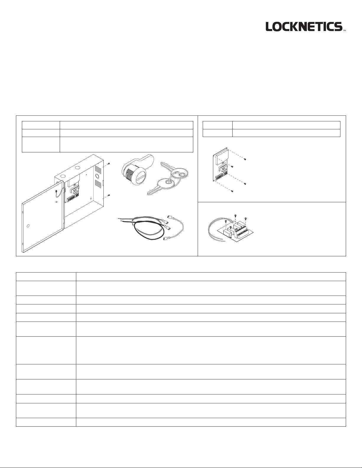
This instruction covers:
LP150 PS cabinet + board (1.5A), battery wire kit, keylock
LP250 PS cabinet + board (2.5A), battery wire kit, keylock
LP250RDB4 PS cabinet + board (2.5A), battery wire kit, keylock,
RDB4 board *
Keylock
LP150B PS board only (1.5A), 4 mounting screws
LP250B PS board only (2.5A), 4 mounting screws
PS board
RDB4 board included
PS150/250
Power Supply
Enclosure
with hinged cover
+ Board
Battery Wire Kit
*
RDB4
with LP250RDB4 only
and is covered in
separate instruction
PS150/250 Specications:
Input LP150: 120 VAC, 1A, 60Hz LP250: 120 VAC, 1.2A, 60Hz
Output LP150: 12 VDC (13.2V nominal) or 24 VDC (26.4V nominal), 1.5A, Class 2 rated
LP250 (LP250RDB4): 12 VDC (13.2V nominal) or 24 VDC (26.4V nominal), 2.5A, Class 2 rated
Output Protection DC OUT and CONTROL OUT are protected from overload or shorts via self-resetting electronic protection circuit
Battery Protection PTC
Environment 32°-120° F (0°- 49° C), up to 85% relative humidity, indoor use only, protected area
Compliance UL294, UL603, Access control performance levels: Attack: I, Line security: I, Endurance: IV, Standby power: III
(LP150) and II (LP250/LP250RDB4), CSA22.2 NO. 205, CSFM, FCC
Battery Backup Requires 12V, 7AH max. rechargeable sealed lead acid battery: (1) for 12V, (2) for 24V output.
Battery maximum dimensions: 3-3/4” H x 6” W x 3” D
See typical backup times in Section 2
See Section 8 for maintenance of battery
Control Input / Output Input: Normally closed, requires dry contact rated at 24 VDC, 10mA
Output: Powered NC/NO contacts rated at 24 VDC, 2.5A
AC Status Indicator: Green LED
Relay contacts: NO/NC contacts rated at 24 VDC, 1A
DC Output Status Indicator: Red LED
Battery Status Indicator: Red LED
Relay contacts: NO/NC contacts rated at 24 VDC, 1A
Enclosure 13” H x 12-5/8” W x 3-1/4” D (8 knockouts, 1/2” or 3/4”)
Denitions:
Normally closed contacts (NC)
Normally open contacts (NO)
FSE - Fail secure (needs power to unlock)
FACP - Fire Alarm Control Panel
ACC - Access Control Contacts
FS - Fail safe (needs power to lock)
See Section 10 for an explanation
of the Warnings and Cautions
used in this booklet.
1 Installation Overview
Wiring methods shall be applied in accordance with the National Electric Code/NFPA 70/NFPA 72/ANSI, and with all local codes and
authorities having jurisdiction.
WARNING
To avoid risk of electric shock, turn off AC power before
installing or servicing LP150/LP250 power supply.
1. Mount unit in a protected area per Section 2.
2. Select voltage (12 or 24 VDC) per Section 3.
3. Connect AC power per Section 3.
• Connect the earth ground to the green/yellow cabinet wire and line (L) and neutral (N) to the appropriate terminals on the AC
terminal block.
Measure output voltage before connecting devices to prevent damage.
4. Disconnect AC power and nish all wiring per Sections 4 and 6.
5. Install battery backup (if required) per Sections 2 and 3.
If AC input goes o and battery backup is not being used, all devices connected to the power supply will be unpowered.
6. AC status may be required for Battery Backup systems (Section 3).
7. Secure cover with screws or keylock when complete per Section 7.
8. For maintenance and troubleshooting, see Sections 8 and 9.
2

2 Mounting
CAUTION
Product intended for indoor use only and within
the temperature range specified. Mount unit in a
protected area. Do not install in locations with
exposure to rain or water.
Enclosure mounting
screws not provided
Mounting Hole
Dimensions
10¹⁵⁄₁₆"
11¹⁄₈"
Enclosure
Dimensions
12⁵⁄₈"
Mount
in upright
position
13"
Cover not shown
for clarity
Battery mounting
to be as shown
3¹⁄₄"
Battery Backup
Time
BACKUP TIME (HOURS)LOAD
CURRENT
(AMPS)
0.2
0.5
1.5
2.5
LP150
19
11
2
LP250
19
11
2
1.25
Calculated battery backup time based
on charging time of 48 hours at a
temperature of 77° F (25° C).
3
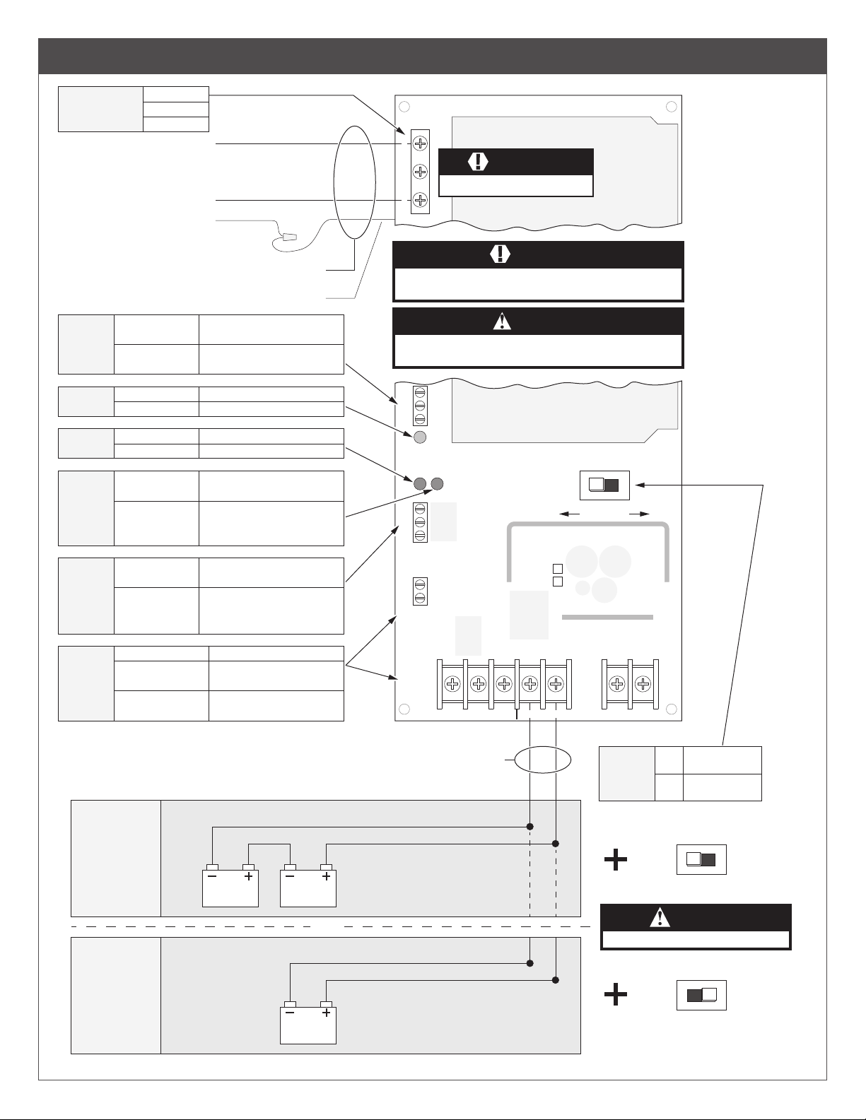
3 Power Supply Board - Features and Operation
120VAC, 60Hz
input voltage
AC
STATUS
120VAC
green LED
DC
red LED
BAT
red LED
BAT
STATUS
L: Line, hot
G: Ground
N: Neutral
NC to C: open
NO to C: closed
NC to C: closed
NO to C: open
off
on
off
on
off
on
NC to C: open
NO to C: closed
NC to C: closed
NO to C: open
Hot
Neutral
Earth Ground
Non power-limited, Class 1
Green/Yellow
120VAC NOT present on input
120VAC present on input
120VAC NOT present on input
120VAC present on input
DC output off or shorted/overload
DC output on (12 or 24V)
Battery not connected or
battery low
Battery connected and
charging or providing battery
backup
Battery not connected or
battery low
Battery connected and
charging or providing battery
backup
120VAC
L
G
N
WARNING
Must be connected via rigid conduit.
WARNING
Keep power-limited wiring separate from non power-limited wiring.
Minimum 1/4" spacing must be provided.
CAUTION
When installing, route field wiring away from sharp projections, corners, and
NC
C
NO
AC STATUS
NC
C
NO
BAT STATUS
IN
C
CONTROL IN
internal components. Deburr all conduit fittings.
BATDC
24V 12V
LP150
LP250
CONTROL
4
CONTROL OUT
NC to DC-: 0V
NO to DC-: DC+ out
NC to DC-: DC+ out
NO to DC-: 0V
24VDC
BATTERY
CONFIGURATION
12VDC
BATTERY
CONFIGURATION
CONTROL IN
IN to C: open contacts
IN to C: closed contacts
Black
Yellow
12V
BATTERY
BATTERY
BATTERY
12V
12V
OR
CONTROL
OUT
Red
Black
Red
NO DC- DC- DC+NC
Non powerlimited
BAT- BAT+
DC
OUT
DC
OUTPUT
VOLTAGE
SELECT
Switch moved to
24V
left position
Switch moved to
12V
right position
24V
CAUTION
Confirm polarity to avoid damage to unit.
12V
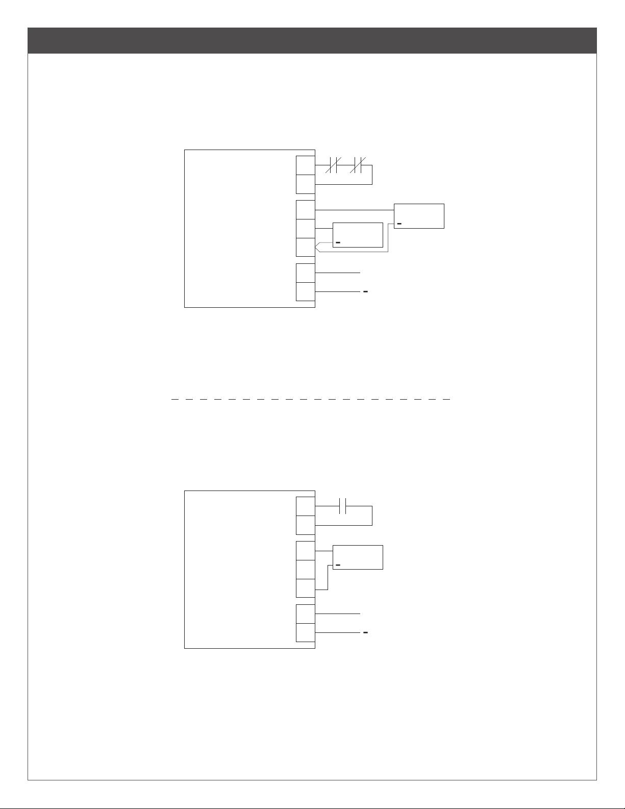
4 Typical Wiring
FS & FSE device connected to
PS board with FACP override
FACPACC
CONTROL
IN
IN
C
NC
LP150/250
Operation:
1. CONTROL IN controls the operation of devices connected to the NO
or NC terminals.
2. Opening of the FACP contacts will unpower the CONTROL OUT NC
contacts and power the NO contacts.
3. DC OUT is always powered regardless of the state of the FACP
contacts.
CONTROL
OUT
DC
OUT
NO
DC-
DC+
DC-
+
E-STRIKE
FSE
+
FSE device using open input
control contacts
ACC
CONTROL
IN
IN
C
+
MAGLOCK
CONTINUOUS
DC OUTPUT
FS
NC
LP150/250
Operation:
1. CONTROL IN controls the operation of the strike connected to the
NC terminal.
2. Closing the ACC contacts will apply power to the FSE strike to unlock it.
CONTROL
OUT
DC
OUT
NO
DC-
DC+
DC-
+
E-STRIKE
FSE
+
CONTINUOUS
DC OUTPUT
5

5 PS150B and PS250B Installation
Enclosure cutaway
shown for clarity
Interior of
enclosure
6-32 x 1/4" (4)
6 Wire run lengths
• Use the following table to estimate the gauge of wire required for the application.
• Wire length based on 15% voltage drop at 12 or 24V using stranded copper wire.
• The wire gauge listed is a minimum. The gauge can be increased if desired.
• Distance = total one way wiring distance between power supply and powered device (includes both power wires).
• For UL installations, the minimum permissible wire size to be used shall not be less than 22AWG.
DISTANCE
(FEET)
100
200
300
400
22
22
20
20
22
18
16
16
18
16
14
14
WIRE GAUGE (AWG)
16
14
12
14
12
22
22
22
22
22
22
20
18
22
18
16
16
20
16
14
14
18
14
12
12
500
6
18
0.2
14
0.5
12
1.0
1.5
LOAD CURRENT AT 12V
(AMPS)
2.5
22
0.2
18
0.5
14
1.0
12
1.5
LOAD CURRENT AT 24V
(AMPS)
2.5

7 Secure enclosure door
If No Keylock
Enclosure will be secured with 2
screws as shown (done as last step)
If Keylock
Remove knockout and insert key cylinder and secure with nut as shown
a b
exterior of door
#6 x 3/8" (2)
AC Status
indicator
c
interior of door
7

8 Maintenance
Unit should be tested at least once a year for proper operation as follows:
Voltage Output:
• Verify the proper DC output voltage by measuring the DC+ and DC- terminals.
Fire Alarm Release (if used):
• Verify proper operation by opening the wiring to the CONTROL IN input. Conrm that the locks controlled by the CONTROL
OUT output unlocked properly.
Battery (if used):
• Verify the proper charge voltage (between 26.3 - 26.5 VDC) on the battery terminals by measuring the BAT+ and BATterminals.
• Batteries should be changed every 4 years. Record date of install inside the cabinet to track time of service.
9 Troubleshooting
Refer to Section 3 for LED status of the AC input, DC output, and Battery to determine the cause for any abnormal condition. Each LED
has the denition of its ON or OFF state.
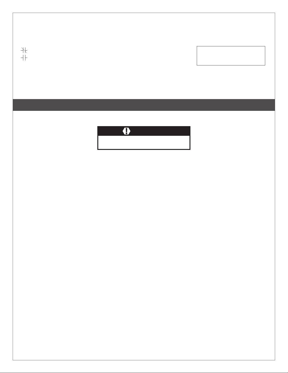
10 Warnings and Cautions
Warnings look like this:
Cautions look like this:
Notices look like this:
Directions look like this:
WARNING
Warnings indicate potentially hazardous conditions, which if not
avoided or corrected, may cause death or serious injury.
CAUTION
Cautions indicate potentially hazardous conditions, which if
not avoided or corrected, may cause minor or moderate injury.
Cautions may also warn against unsafe practices.
Notices indicate a condition that may cause
equipment or property damage only.
Directions identify a step that may or may not
apply to your product configuration. It also may
direct you to another part of the instruction.
8

LP150, LP250
Bloc d’alimentation
LP150B, LP250B
Instructions d’installation
LP250RDB4
Le LP150/LP250 est un bloc d’alimentation limitée en puissance et un chargeur de batterie qui convertissent l’alimentation de 120 V/60
Hz en puissance nominale de classe 2 de 12 ou 24 VCC sélectionnables sur site (continue et commutable). Il est destiné à être utilisé
dans des applications répondant aux exigences UL (voir les spécications ci-dessous pour une liste spécique).
Ces instructions couvrent :
LP150 Armoire électrique + tableau (1,5 A), ensemble de
câblage pour batterie, verrou à clé
LP250 Armoire électrique + tableau (2,5 A), ensemble de
câblage pour batterie, verrou à clé
LP250RDB4 Armoire électrique + tableau (1,5 A), ensemble de
câblage pour batterie, verrou à clé, carte RDB4 *
Verrou à clé
Armoire électrique
PS150/250 avec couvercle
à charnière + tableau
Ensemble de câblage
pour batterie
LP150B Armoire électrique seulement (1,5 A), 4 vis
LP250B Armoire électrique seulement (2,5 A), 4 vis
Armoire électrique
* La carte RDB4 est
fournie avec LP250RDB4
RDB4
uniquement. Elle est
couverte dans des
instructions séparées
Caractéristiques techniques des PS150/250 :
Entrée LP150: 120 V, 1 A, 60 Hz LP250: 120 V, 1,2A, 60 Hz
Sortie LP150 : 12 V (13,2 V nominal) ou 24 V (26,4 V nominal), 1,5 A, classe 2
LP250 (LP250RDB4): 12 V (13,2V nominal) ou 24 V (26,4V nominal), 2,5A, classe 2
Protection de sortie Les ports DC OUT et CONTROL OUT sont protégés contre les surcharges et les courts-circuits grâce à un
circuit de protection électronique à réamorçage automatique
Protection de la
batterie
Environnement 32 ° - 120 ° F (0 ° - 49 ° C), humidité relative jusqu’à 85%, utilisation à l’intérieur uniquement, zone protégée
Conformité UL294, UL603, Niveau de performance: Attaque destructive : niveau I, protection des lignes : niveau I,
Batterie de secours Nécessite 12 V, 7 AH max. batterie plomb-acide scellée rechargeable : (1) pour 12 V, (2) pour une sortie 24 V.
Contrôle de l’entrée/
sortie
État CA Indicateur : LED vert
Etat de la sortie CC Indicateur : LED rouge
État de la batterie Indicator: Red LED
Enceinte 13 po x 12-5/8 po x 3-1/4 po (8 entrées, 1/2 po ou 3/4 po)
PTC
Puissance en veille : niveau III, Résistance: niveau IV, (LP150) and II (LP250/LP250RDB4), CSA22.2 NO.205,
CSFM, FCC
Dimensions maximales de la batterie : 3-3/4 po x 6 po x 3 po
Voir les temps de sauvegarde typiques dans la section 2
Voir la section 8 pour l’entretien de la batterie
Entrée: normalement fermée, nécessite un contact sec de 24 V, 10 mA
Sortie : normalement fermé/ouvert alimenté pour 24 V, 2,5 A
Contacts de relais : normalement ouvert/fermé à 24 V, 1 A
Contacts de relais : normalement ouvert/fermé à 24 V, 1 A
9

Dénitions :
Contacts normalement fermés (NC)
Contacts normalement ouverts (NO)
FSE - Sécurité intégrée (besoin d'alimentation
pour déverrouiller)
FACP - Panneau de contrôle d'alarme
incendie
ACC - Contacts de contrôle d'accès
FS - Sûreté intégrée (besoin d'alimentation
pour verrouiller)
Voir la section 10 pour
une explication des
avertissements et mises
en garde utilisés dans
cette brochure.
1 Aperçu de l’installation
Les méthodes de câblage doivent être appliquées conformément au Code Électrique National/NFPA 70/NFPA 72/ANSI, ainsi qu’aux
codes et autorités locales compétents.
ATTENTION
Pour éviter tout risque de décharge électrique, mettez l’appareil hors
tension avant d’installer ou de réparer l’alimentation LP150/LP250.
1. Installez l’appareil dans une zone protégée conformément à la section 2.
2. Sélectionnez la tension (12 ou 24 V) selon la section 3.
3. Branchez l’alimentation CA conformément à la Section 3.
• Connectez la mise à la terre au l vert/jaune de l’armoire et la ligne (L) et le neutre (N) aux bornes appropriées du bornier CA.
Mesurez la tension de sortie avant de connecter des appareils pour éviter tout dommage.
4. Débranchez l’alimentation CA et terminez tout le câblage conformément aux sections 4 et 6.
5. Installez une batterie de secours (si nécessaire) conformément aux sections 2 et 3.
Si l’entrée CA est désactivée et la batterie de secours n’est pas utilisée, tous les périphériques connectés à l’alimentation ne seront
plus alimentés.
6. L’état de l’alimentation peut être nécessaire pour les systèmes à batterie de secours (section 3).
7. Fixez le couvercle avec des vis ou un verrou à clé lorsque vous avez terminé, conformément à la section 7.
8. Pour la maintenance et le dépannage, voir les sections 8 et 9.
10

2 Installation
MISE EN GARDE
Le produit destiné à une utilisation en intérieur
uniquement et dans la plage de température spécifiée.
Installez l'unité dans une zone protégée. Ne l'installez
pas dans des endroits exposés à la pluie ou à l'eau.
trou d'installation
Vis d'installation du
boîtier non fournies
Dimensions du
10-15/16 po
11-1/8 po
Dimensions de
l'armoire
12-5/8 po
Installez
en
position
verticale
13 po
Couverture non
illustrée pour plus
de clarté
L'installation de la batterie
doit être comme indiquée
3-1/4
po
Temps de sauvegarde
de la batterie
TEMPS DE SAUVEGARDE (HEURES)COURANT DE
CHARGE
(AMPS)
0.2
0.5
1.5
LP150
19
11
2
2.5
Le temps de sauvegarde calculer de la
batterie basé sur un temps de charge de 48
heures à une température de 77 ° F (25 ° C).
LP250
19
11
2
1.25
11

3 Tableau d’alimentation - Caractéristiques et fonctionnement
120 V, tension
d'entrée 60 Hz
L: Ligne, alimentée
G: Mise à la terre
N: Neutre
Normalement fermé à C : ouvert
ÉTAT
Normalement ouvert à C : fermé
CA
Normalement ouvert à C : fermé
Normalement ouvert à C : ouvert
120 V ligne
désactivé
verte
LED rouge CCdésactivé
désactivé
LED rouge
BAT
Normalement fermé à C : ouvert
ÉTAT
Normalement ouvert à C : fermé
DE LA
BATTERIE
Normalement ouvert à C : fermé
Normalement ouvert à C : ouvert
SORTIE DES CONTRÔLES
Normalement fermé à DC : 0 V
CONTRÔLE
NO À CC : CC + sortie
Normalement fermé à DC: CC + sortie
Normalement fermé à DC : 0 V
Alimentée
Neutre
Mise à la terre
Non limité en puissance, classe 1
120 V NON présent à l'entrée
activé
120 V présent à l'entrée
Sortie CC désactivée ou en
court-circuit / surcharge
activé
Sortie DC activée (12 ou 24V)
Batterie non connectée ou
batterie faible
Batterie connectée et en
activé
charge ou fournissant une
batterie de secours
Vert/jaune
120 V NON présent à
l'entrée
120 V présent à l'entrée
Batterie non
connectée ou
batterie faible
Batterie connectée
et en charge ou
fournissant une
batterie de secours
ENTRÉE DES CONTRÔLES
ENTRÉE à C : contacts ouverts
ENTRÉE à C : contacts fermés
120VAC
L
G
N
ATTENTION
Doit être connecté via un conduit ridige.
ATTENTION
Gardez le câblage limité en puissance séparé du câblage non limité en
puissance. Un espacement minimum de 1/4 po doit être fourni.
MISE EN GARDE
Lors de l'installation, éloignez le câblage des projections, des angles et des
composants internes pointus. Ebavurer tous les raccords de conduit.
NC
C
NO
AC STATUS
BATDC
NC
C
NO
BAT STATUS
IN
C
CONTROL IN
CONTROL
OUT
NO DC- DC- DC+NC
Non limité en
puissance
LP150
LP250
BAT- BAT+
24V 12V
SÉLECTION
DE TENSION
DE SORTIE
CC
DC
OUT
Commutateur
24V
déplacé à gauche
Commutateur
12V
déplacé à droite
12
CONFIGURATION
DE LA BATTERIE
24 V
CONFIGURATION
DE LA BATTERIE
12 V
12V
BATTERIE
Noir
Jaune
12V
BATTERIE
OU
12V
BATTERIE
Rouge
Noir
Rouge
24V
MISE EN GARDE
Confirmez la polarité pour éviter
d'endommager l'appareil.
12V

4 Câblage typique
Dispositif FS et FSE connecté à la
carte PS avec neutralisation FACP
FACPACC
ENTRÉE DES
CONTRÔLES
IN
C
NC
LP150/250
Opération :
1. CONTROL IN contrôle le fonctionnement des appareils connectés
aux bornes NO ou NC.
2. L’ouverture des contacts FACP désactive les contacts CONTROL
OUT NC et alimente les contacts NO.
3. DC OUT est toujours alimenté, quel que soit l'état des contacts du
FACP.
SORTIE DES
CONTRÔLES
SORTIE
CC
NO
DC-
DC+
DC-
+
GÂCHE
ÉLECTRIQUE FSE
+
SORTIE CC
CONTINUE
Dispositif FSE utilisant des contacts
de contrôle d'entrée ouverts
ACC
ENTRÉE DES
CONTRÔLES
IN
C
+
MAGLOCK
FS
NC
LP150/250
Opération :
1. CONTROL IN contrôle le fonctionnement de la gâche connectée à la
borne NC.
2. La fermeture des contacts de l'ACC alimentera la frappe FSE pour la
déverrouiller.
SORTIE DES
CONTRÔLES
SORTIE
CC
NO
DC-
DC+
DC-
+
GÂCHE
ÉLECTRIQUE FSE
+
SORTIE CC
CONTINUE
13

5 Installation de PS150B et PS250B
Vue en coupe du
boîtier pour plus de
clarté
Intérieur de
l'enceinte
6-32 x 1/4 po (4)
6 Longueurs de l
• Utilisez le tableau suivant pour estimer le calibre de l requis pour l’application.
• Longueur de l basée sur une chute de tension de 15 % à 12 ou 24 V avec un l de cuivre toronné..
• Le calibre de l indiqué est un minimum. La jauge peut être augmentée si vous le souhaitez.
• Distance = distance totale de câblage unidirectionnel entre l’alimentation et le périphérique alimenté (inclut les deux câbles
d’alimentation).
• Pour les installations UL, la taille de câble minimum permis à utiliser ne doit pas être inférieure à 22 AWG.
DISTANCE
(PIEDS)
100
200
300
400
22
22
20
20
22
18
16
16
18
16
14
14
JAUGE DE FIL (AWG)
16
14
12
14
12
22
22
22
22
22
22
20
18
22
18
16
16
20
16
14
14
18
14
12
12
14
500
18
0.2
14
0.5
12
1.0
COURANT DE CHARGE À 12V
(AMPÈRES)
1.5
2.5
22
0.2
18
0.5
14
1.0
COURANT DE CHARGE À 24V
(AMPÈRES)
12
1.5
2.5

7 Porte sécurisée
Si pas de serrure
Le boîtier sera fixé avec 2 vis
comme indiqué (à la dernière étape)
Si une serrure est présente
Retirez la découpe, insérez le barillet et fixez-le avec l'écrou comme indiqué
a b
extérieur de la
porte
# 6 x 3/8 po (2)
Indicateur
d'état CA
c
intérieur de la
porte
15

8 Entretien
L’unité doit être testée au moins une fois par an pour vérier son bon fonctionnement, comme suit:
Tension de sortie:
• Vériez la tension de sortie CC appropriée en mesurant les bornes DC + et DC-.
Déclenchement d’alarme incendie (si utilisé):
• Vériez le bon fonctionnement en ouvrant le câblage de l’entrée CONTROL IN. Conrmez que les serrures contrôlées par le
CONTROL Sortie sortie déverrouillée correctement.
Batterie (si utilisée):
• Vériez la tension de charge appropriée (entre 26,3 et 26,5 V) aux bornes de la batterie en mesurant les bornes BAT + et
BAT-.
• Les piles doivent être remplacées tous les 4 ans. Notez la date d’installation à l’intérieur de l’armoire pour suivre l’heure de
réparation.
9 Dépannage
Reportez-vous à la section 3 pour connaître l’état des voyants de l’entrée CA, de la sortie CC et de la batterie an de déterminer la cause
de toute condition anormale. Chaque voyant a la dénition de son état ON ou OFF.
10 Avertissements et mises en garde
Les avertissements
ressemblent à ceci :
Les mises en garde
ressemblent à ceci :
Les avis ressemblent
à ceci :
Les instructions
ressemblent à ceci :
AVERTISSEMENT
Les avertissements indiquent des conditions potentiellement
dangereuses qui, si elles ne sont pas évitées ou corrigées, peuvent
provoquer des blessures graves, voire mortelles.
MISE EN GARDE
Les mises en garde indiquent des conditions potentiellement
dangereuses qui, si elles ne sont pas évitées ou corrigées,
peuvent causer des blessures mineures ou modérées. Les
mises en garde peuvent également mettre en garde contre les
pratiques dangereuses.
Les avis indiquent une condition pouvant
uniquement causer des dommages
matériels.
Les instructions identifient une étape qui peut
ou non s'appliquer à la configuration de votre
produit. Cela peut également vous diriger vers
une autre partie de l'instruction.
16
Customer Service
1-877-671-7011 www.allegion.com/us
Canada
1-800-900-4734 www.allegion.ca
© Allegion 2019
Printed in Taiwan
829767-00 Rev. 06/19-b
 Loading...