

Page 1
*P516-955*
P516-955
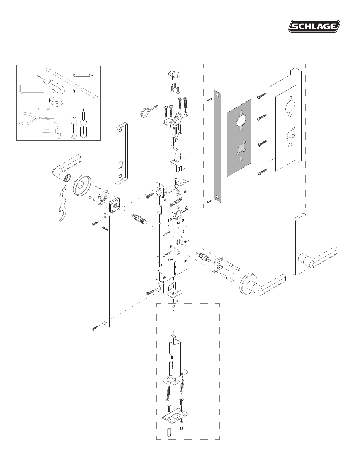
Lever by lever mortise lock for wood and hollow metal doors Installation instructions
Tools
B\cx"
LM9200-Series
For re-rated wood
door application
For two
point latch
application
Page 2
1 Table of contents
Door preparation .........................................................2
Fire barrier installation (re-rated wood door only) .....3
Install latch(es) ............................................................5
Check cable spool(s) position. .................................... 6
Install mortise chassis .................................................7
Check latch operation – top latch ................................ 8
Check latch operation – bottom latch .......................... 9
Lock the latch(es) ...................................................... 10
Secure the mortise .................................................... 11
Strikes and re pin .................................................... 11
Install levers and cylinders (if applicable) .................. 13
Install armor front plate .............................................14
Install interior lever assembly .................................... 15
Check latch position(s) .............................................. 16
Complete top strike installation .................................17
1 Door preparation
LM9200 Product description and overview
• Two-point latching system that utilizes concealed cables to
secure the opening at the top and bottom of the door.
• Available less bottom latch for “top latch only” applications.
• Intended for use in pair door applications where both leaves
need to be active.
• Based on Schlage L mortise lock and available with most
Schlage L levers, trims and options.
• Requires door prepped specically for the Schlage LM9200.
Technical Support hot line: 877-671-7011
Scan this QR code or visit us online at kc.allegion.com to access
the Allegion Knowledge Center.
Need a reader for your phone?
For iPhone: QR Reader
For Android: QR Barcode Scanner
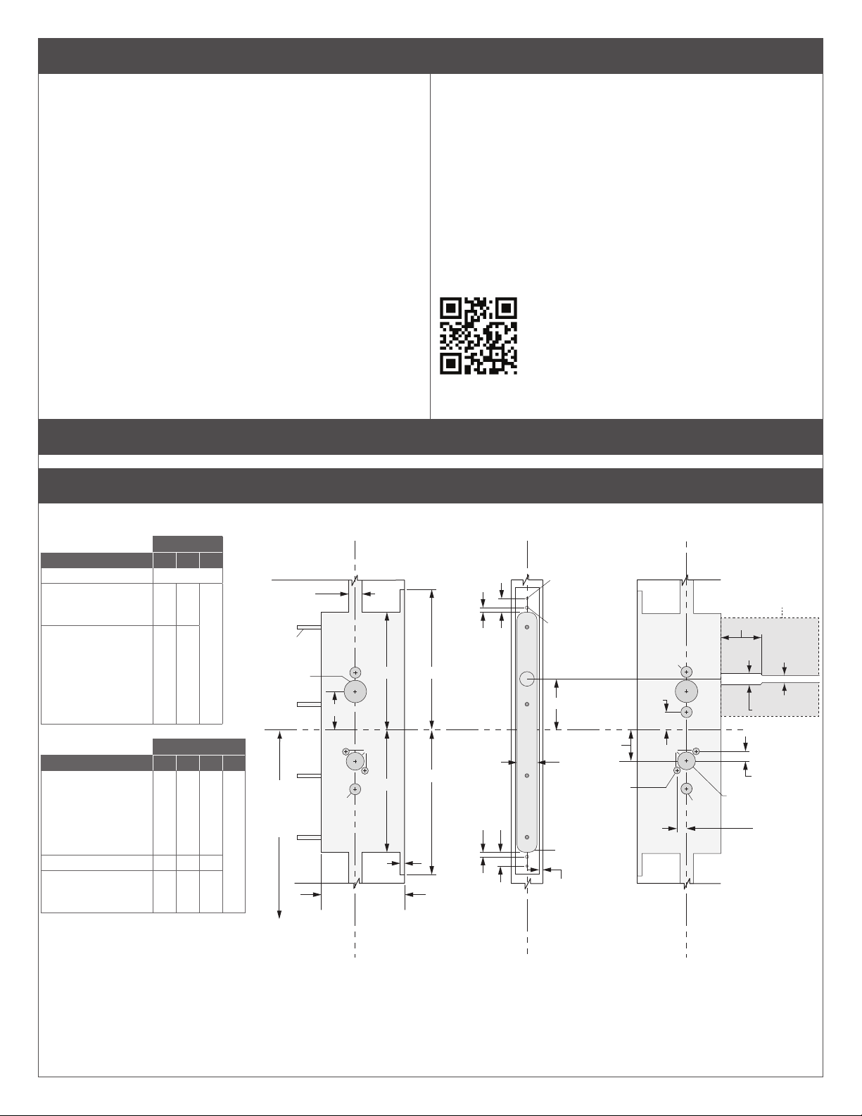
1a Check door preparation dimensions.
If door preparation dimensions do not match, go to www.schlage.com for door preparation instructions or refer to the enclosed template.
OUTSIDE
Functions A D E
LM9225
LM9210,
LM9290EL/EU,
LM9291EL/EU
LM9250, LM9256,
LM9270, LM9271,
LM9280,
LM9292EL/EU,
LM9293EL/EU,
LM9294EL/EU,
LM9295EL/EU
No holes
X X
INSIDE
Functions B C D E
LM9210, LM9225,
LM9270, LM9280,
LM9290EL/EU,
LM9291EL/EU,
LM9292EL/EU,
LM9293EL/EU
LM9250, LM9256
LM9271,
LM9294EL/EU,
LM9295EL/EU
X
X
Escutcheon trim
Escutcheon trim
X
X
X
X
.750"
Fire door
only x4
Ø 1.250"
39.625"
To finished
floor
.766"
.250"
E
2.141"
E
Ø.625"
6.575"
A
D
6.825"
.250"
7.840"
8.080"
4.656"
.250"
.774"
Outside Inside
Ø .136"
(#29 drill)
1.000 deep
2 places
Ø .177"
(#16 drill)
1.000 deep
2 places
2.625"
1.125"
R .438"
4 places
.203"
1.719"
Ø .375" x2
1.000"
Ø.625"
D
E
C
B
E
Ø.625"
EL/EU
Functions only
2.625"
.375"
.750"
.531" x2
Ø 1.000"
.531" x2
Wood door preparation shown above. For hollow metal door preparation, refer to
enclosed template.
2
Page 3
1b Check top strike cutout.
IMPORTANT: THE CUTOUT FOR THE TOP STRIKE MUST BE
ON THE STOP SIDE OF THE DOOR.
If the cutout is not on the stop side of the
door, contact the door distributor.
Top strike
cutout
2³⁄₄"
Backset
1³⁄₁₆"
1³⁄₁₆"
⁵⁄₈"
of Routing
⁹⁄₃₂"
Stop side of door
³⁄₄"
1"
Top strike cutout
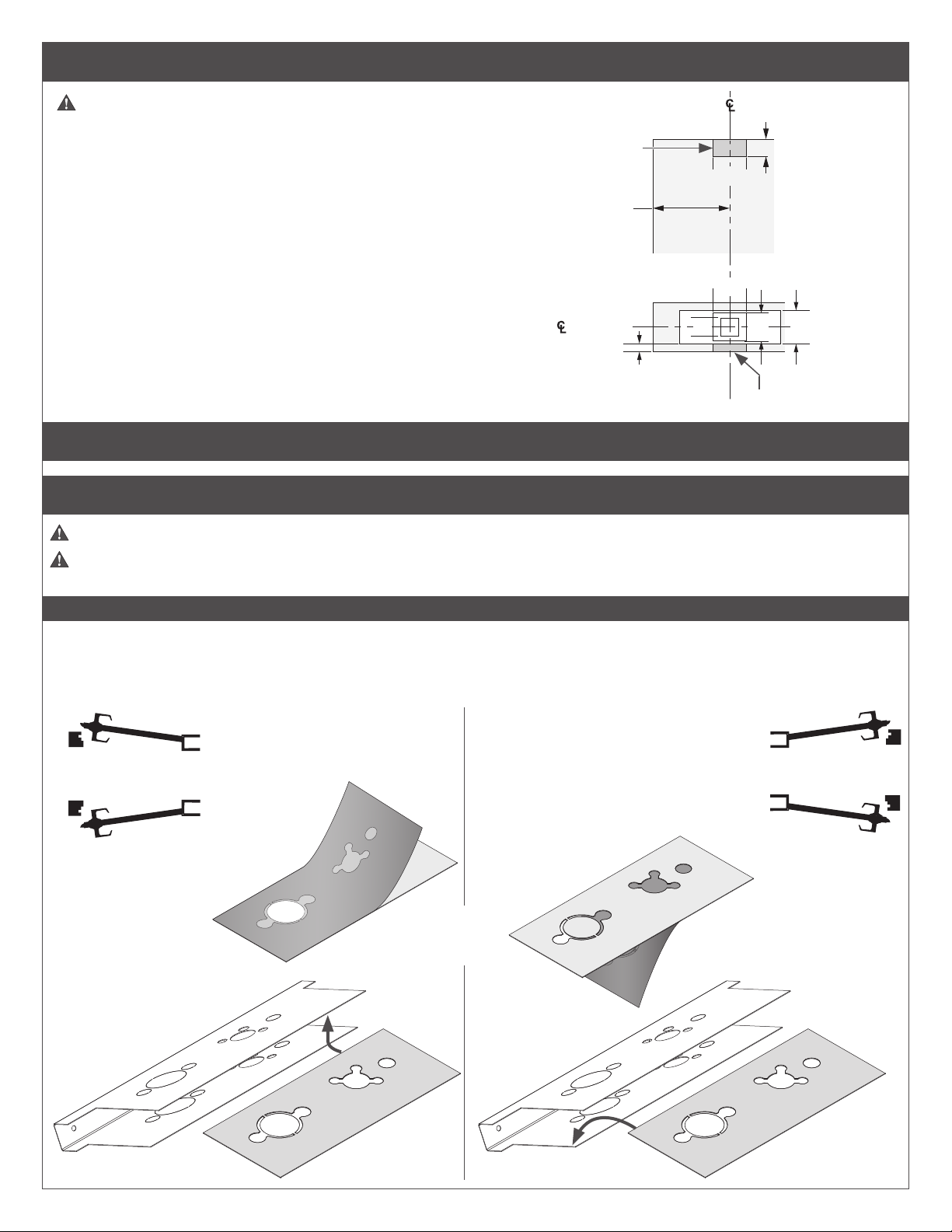
2 Fire barrier installation (re-rated wood door only)
2a Install intumescent.
Fire components must be installed to maintain re rating of the opening.
Note door handing on intumescent. The intumescent is applied to the side of the re barrier that will be opposite
the door stop.
CAUTION!
Intumescent must be properly aligned before adhesive contacts the re barrier surface.
Adhesive is permanent and not repositionable.
Peel one side of the adhesive backing from intumescent as shown.
Apply the intumescent adhesive to the re barrier.
INSIDE
OUTSIDE
RH
Right Hand
LH
Left Hand
1³⁄₁₆"
INSIDE
OUTSIDE
INSIDE
OUTSIDE
RR
Right Hand
Reverse
(1)
(2)
OR
(1)
(2)
LR
Left Hand
Reverse
INSIDE
OUTSIDE
3
Page 4
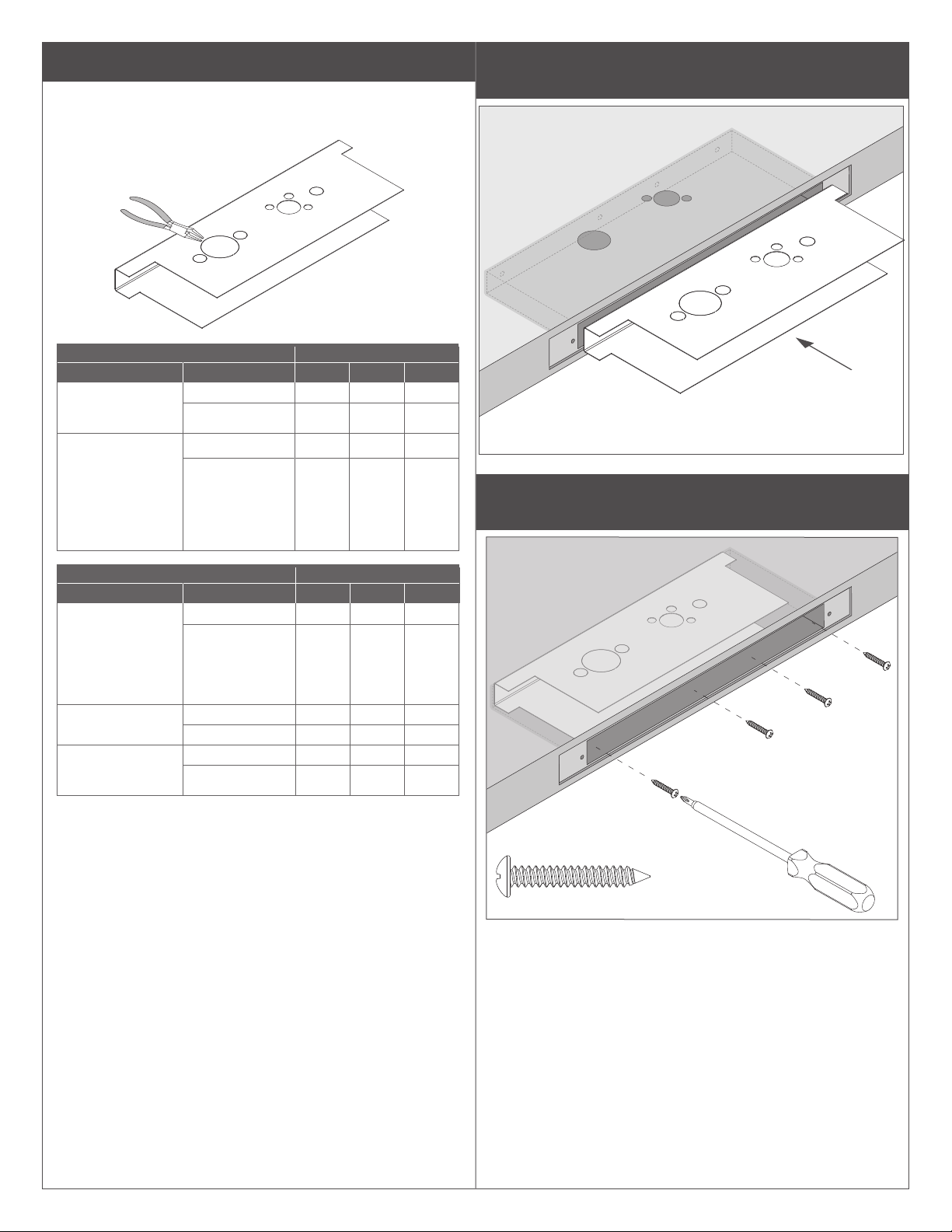
2b Remove knockouts from re barrier.
Remove knockouts per door handing and function.
A
C
B
A
Exterior Remove knockout
Function Trim
LM9210, LM9225,
LM9290EL/EU,
LM9291EL/EU
LM9250, LM9256,
LM9270, LM9271,
LM9280,
LM9292EL/EU,
LM9293EL/EU,
LM9294EL/EU,
LM9295EL/EU
Rose
Escutcheon ●
Rose ●
Escutcheon ● ●
A B C
2c With re barrier in correct orientation, slide barrier into
door pocket.
TOP
RH, LR door shown with top notch
cutout (door stop side) facing down.
2d Secure the re barrier inside the mortise pocket with
four screws.
Interior Remove knockout
Function Trim
LM9210, LM9225,
LM9270, LM9280,
LM9290EL/EU,
LM9291EL/EU,
LM9292EL/EU,
LM9293EL/EU
LM9250, LM9256
LM9271,
LM9294EL/EU,
LM9295EL/EU
A B C
Rose
Escutcheon ●
Rose ●
Escutcheon ● ●
Rose ●
Escutcheon ● ●
4
Page 5

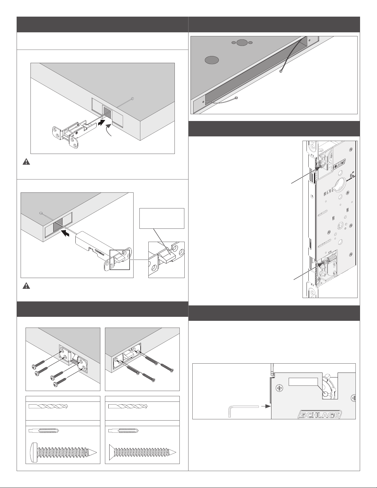
3 Install latch(es)
3a IMPORTANT! Check lock handing before installation.
3d Connect cable end tting(s) to latch(es).
Top latch: Pull cable link down. Slide cable end into cable link.
Bottom latch: Bend cable slightly to access cable link, then install.
LM9210 does not use a lock handing screw.
To change handing:
Remove the lock
handing screw from
one side of the
chassis and install it
on the opposite side.
The lock handing
screw should always
be on the interior
(door stop) side of the
door.
3b FOR ELECTRIFIED LOCKS ONLY: If necessary,
move EL/EU switch to desired position before
installation.
Top latch
Cable
link
Pull
L Refer to illustrations to identify top and bottom latches.
L For 2-point latches, the bottom cable is black.
Bottom latch
For 2-point latch only
Bend
Cable
link
3e
Set the door on sawhorses with the top notch cutout (door stop
side) facing down.
BOTTOM
EL/EU
switch
3c Conrm top latch is marked for LM9200 LOCK ONLY,
then remove label.
ATTENTION:
FOR USE WITH
LM9200 LOCK ONLY
TOP
5
Page 6
3f Feed the cable(s) through the door.
The ends of the cables will rest in the mortise pocket.
Insert the top latch into the door.
TOP
Notch
cutout
Check handing. The top latchbolt should swing toward the
notch cutout side of the door.
3h Perform cable binding check at the mortise pocket.
Pulling on bottom
cable should retract
the bottom latch
(2-point latch only).
TOP
Pulling on top cable should
lock and unlock the top latch.
Cable adjustment points
L Adjustment points referenced in
the remainder of this instruction
are shown here.
Insert the bottom latch into the door (2-point latch only).
BOTTOM
Check handing. The bottom latchbolt bevel should face
opposite the notched cutout side of the door.
Bevel faces
opposite notched
side of door
3g Secure the latch(es).
Top Bottom (for 2-point latch only)
Top cable
spool screw
Bottom cable
spool screw
4 Check cable spool(s) position.
Check spool(s) to be sure they are in unretracted state (toward top
and bottom of the mortise chassis).
If the spool cable hole is not visible or only partially visible,
rotate the cable spool screw with hex wrench to reveal the
cable hole.
Wood
#25 drill, pilot 1Z\x" deep x4
Metal
#10-24, UNC-2B
Wood
#25 drill, pilot 1Z\x" deep x4
Metal
#10-24, UNC-2B
L See "Cable adjustment
points" above for an
illustration of the spool
screws.
B\cx"
Cable hole
6
Page 7
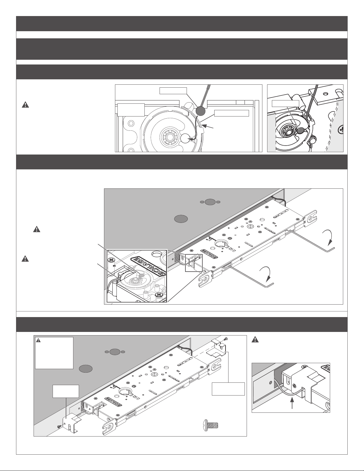
5 Install mortise chassis
5a FOR ELECTRIFIED LOCKS ONLY: Route the wire harness and wiring into the prepared channel before proceeding
with installation.
5b Attach cable end(s) to spool(s).
Feed the cable through the spool.
Fit the cable end into the cable hole.
Check that the cable is properly
routed through the spool.
For 2-point latch only:
The bottom spool access is on the
opposite side of the mortise. Turn the
mortise over to access the bottom
spool.
Top spool
shown
Cable end
Cable end
Wire retainer
Cable must
be positioned
over the wire
retainer.
5c Turn spool to move cable end tting.
Turn the cable spool screw(s) clockwise at top and bottom (if applicable) of the mortise chassis to rotate the spool until the cable end
tting is beneath the mortise cover. Do not turn counter-clockwise.
BOTTOM
Check the cable end
tting(s). The end tting(s)
should be under the
mortise cover.
TOP
Cable must be positioned
over the wire retainer.
5d Install the top and bottom spool covers on the mortise chassis.
Spool
covers must
be installed to
protect the lock
from debris.
Top spool
cover
Check to be sure the cable
is properly fed through the
spool cover slot.
Bottom
spool cover
#6 x ¼"
7
Page 8
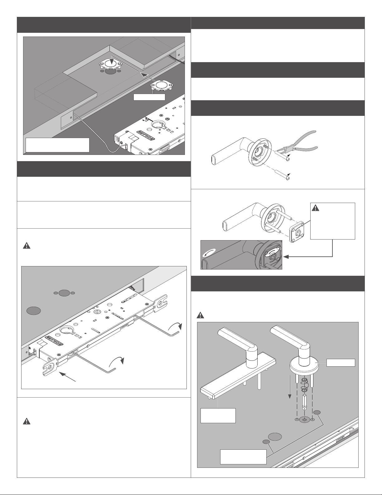
5e LM9225 ONLY: Install inside mounting plate.
Posts down
Install mounting plate on
stop side (interior side).
5f
Hold the mortise chassis away from the pocket so that the cables
are slightly taut.
IMPORTANT
If clicking noises are heard during clockwise adjustment,
unwind the cable with one -half turn counter-clockwise. Then,
continue clockwise adjustment. If clicking persists, check that
cable is not caught on an edge or jammed at spool covers.
6 Check latch operation – top latch
L The following steps are shown with rose trim. Escutcheon is
installed in the same manner except where shown otherwise.
6a Assemble the exterior lever.
Attach mounting posts to the lever.
Fully tighten
mounting posts
on the screws.
Place spring cage on the lever.
Turn the cable spool screw(s) clockwise.
For 2-point latch, alternate between top and bottom.
The mortise chassis will pull into the pocket.
Before the mortise chassis is completely inside the pocket,
check that the cable is not caught on the mortise chassis or a
spool cover.
The spring
cage arrows
must point in
direction of lever
down rotation.
6b
Place the exterior lever assembly and the spindle and spring into
the door.
Do not fasten the exterior lever to the door at this time.
Rose trim
Continue to turn the cable spool screw(s) clockwise (alternating
top and bottom for 2-point latch).
DO NOT OVERTIGHTEN!
Stop turning the spool screw(s) when the mortise chassis is
completely inside the door.
Additional adjustment will be done at a later step.
Escutcheon
trim
L Escutcheon
trim only
8
Page 9
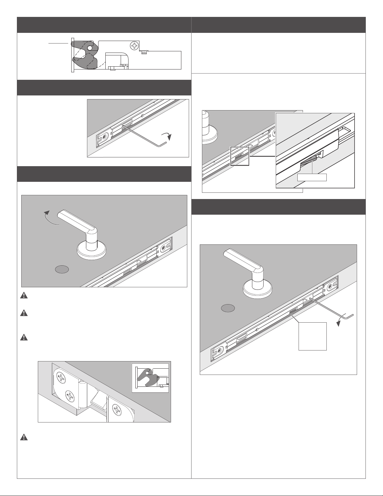
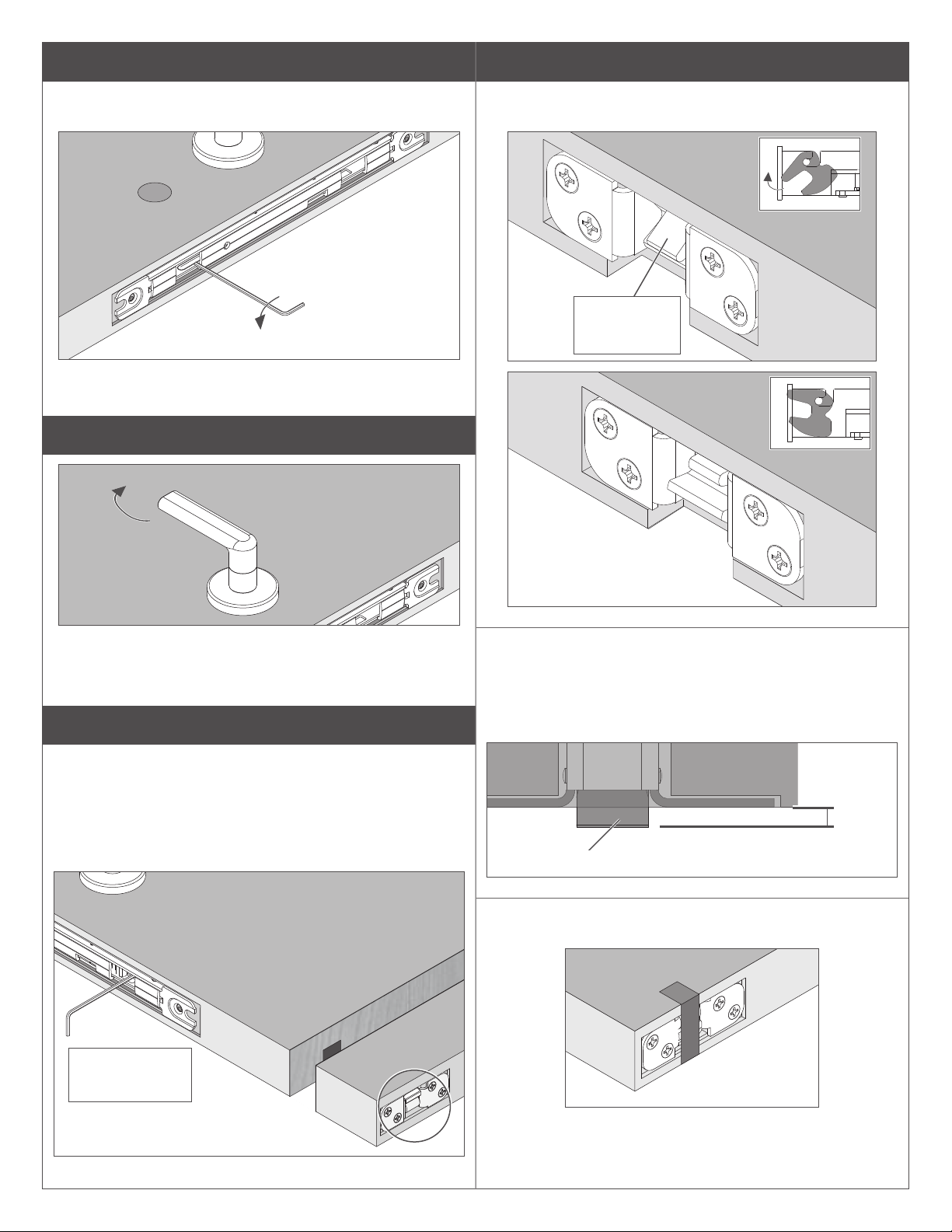
6c Put top latch in locked position.
7 Check latch operation – bottom latch
Locked
6d Turn top cable adjustment screw clockwise.
Turn top screw until a
clicking sound is heard
from the spool.
6e Rotate the exterior lever to release the latch(es).
After lever is rotated, latch(es) should stay in released position.
The tilting link indicates a 2-point system is properly adjusted.
With latches released as described at step 6e, check the center
slot on the front edge of the mortise case. The tilting link should be
visible extending slightly at the opening as shown below.
If the tilting link is visible slightly extended at the center slot,
skip to page 10, step 7d.
If the tilting link IS NOT extended slightly at the center slot
opening as shown, follow the instructions at step 7a below.
Tilting link
7a
If lever droops or does not return to home position, check
spring cage for correct orientation (see illustration at step 6a).
If lever does not rotate enough to release latch(es), turn
the bottom cable spool screw counter-clockwise (2-point latch
only) until the lever rotates fully and releases the top latch.
If the latch(es) do not stay in the released position, rotate
the top latchbolt by hand to released position.
See illustrations below.
Turn the bottom cable spool screw counter-clockwise 3 turns.
The tilting link should be visible extending slightly at the center slot
(see illustration above ).
Observe
tilting link
at center
slot
If the tilting link is visible slightly extended at the center slot,
skip to page 10, step 7d.
If the tilting link IS NOT visible extended slightly at the center
slot, follow the instructions at step 7b.
Top latch released
If the top latch does not rotate when pushed by hand, then
turn the top cable spool screw clockwise until clicking is heard
from the top spool.
If clicking is heard immediately, check that the cable is not caught
or jammed.
9
Page 10
7b
8 Lock the latch(es)
Turn the top cable spool screw counter-clockwise one
additional turn.
The tilting link should now be visible extending slightly at the
center slot opening.
7c Check rotation of the lever.
Lock (extend) the top latch by hand. If applicable, the bottom latch
should also lock.
Pull the top
latch as shown
to lock.
Latch locked
If the lever does not rotate, turn the bottom cable spool screw
counter-clockwise 1-2 turns. Then, repeat rotation of the lever.
Both latches should be released.
7d Check bottom latchbolt.
• The bottom latchbolt should be ush with the bottom of the
door, or may extend not more than Z\,” past the bottom surface
of the door.
• If the bottom latchbolt extends more than Z\,” past the bottom
surface of the door, adjust the bottom cable adjustment
screw clockwise until the latchbolt is ush or not more than
Z\,” past the bottom surface of the door.
Adjust bottom
cable adjustment
screw if necessary
For 2-point latch only:
Check the bottom latch to be sure it is extended. The bottom
latchbolt should extend >\znʺ past the bottom door surface.
Additional adjustment of the bottom latch is described in later
steps.
>\zn"
reference
Bottom latchbolt
While turning the lever, tape the bottom latchbolt to the door ush
with the bottom of the door.
10
Page 11
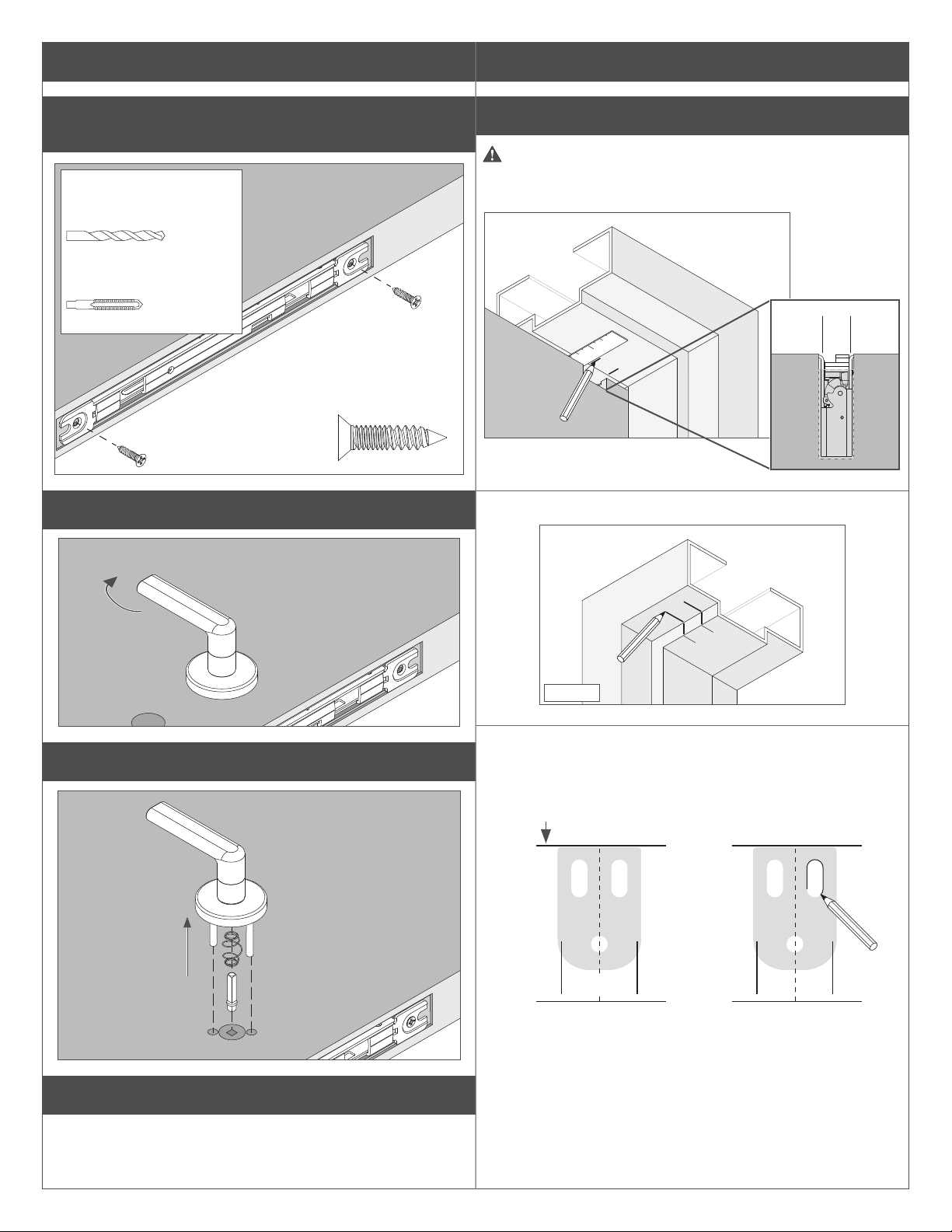
9 Secure the mortise
10 Strikes and re pin
9a Secure the mortise to the door with two mounting
screws.
If necessary, drill pilot holes
for mounting screws.
Wood
#16 drill, 1.0" deep x2
Metal
#12-24, UNC-2B
9b Rotate the lever to release the top latch.
10a Prepare door frame for top strike.
If using a door seal or gasket, install rst.
With door nearly closed, use straight edge to transfer location of
inside edges of top latch housing to underside of stop (a).
a
Interior
Transfer marks to underside of frame (b).
b
9c Remove the exterior lever assembly from the door.
9d Hang the door.
Exterior
With at end of strike against stop, center strike to marks on
frame (c).
Use a pencil to trace contour of the two slotted holes (d).
Edge of stop or gasket
d
c
11
Page 12

Mark the bottom center point of each slot (e) and prepare door
frame as shown.
DO NOT DRILL THIRD HOLE AT THIS TIME.
Wood
10c Prepare oor for bottom strike (2-point latch only).
Latch
Chisel out pocket
¹⁄₂" deep
1¹⁄₄"
Z\," (3.2 mm) drill
e
Pilot 1" deep x2
Metal
Center punch + Z\zn"
pilot holes
#25 x C\v" deep x2
#10-24
10b Install top strike.
Install two (2) top strike screws using the slot features on the
strike.
1"
1" 1"
⁷⁄₈" ¹⁄₂"
³⁄₈" dia.
x 1¹⁄₄" deep
2 places
Door Stop Side
10d Install bottom strike (2-point latch only).
Clear holes of debris, then drop in anchors (a), slotted end rst.
a
Typical installation requires
one thick and one thin
shim. Adjust as necessary.
150 Top Strike
WoodMetal
Secure the anchors using a hammer and punch (b).
b
IMPORTANT!
Anchors must be
below ush.
Install strike plate and secure with two (2) screws (c).
c
450 Bottom Strike
12
Page 13

10e Install re pin (re door one-point application only).
Follow the instructions included with the re pin kit.
11 Install levers and cylinders (if applicable)
IMPORTANT
FOR LOCKS WITH INDICATOR, REFER TO SEPARATE
INSTRUCTIONS FOR INDICATOR TRIM INSTALLATION
11a Install the exterior trim (all except LM9225).
Escutcheon
trim
Spring
cage arrow
must point in
direction of
lever down
rotation.
11c ROSE TRIM ONLY: Install cylinder(s) (if applicable).
With key halfway into cylinder,
insert cylinder, compression
ring and cylinder spring.
L For double cylinder applications, follow the steps above
for the interior cylinder.
Rotate key and cylinder
clockwise.
L Escutcheon
trim only
Rose trim
11b Install interior spindle, spring, spring cage and
mounting plate with two screws.
Spring
cage arrow
must point in
direction of lever
down rotation.
Tighten the cylinder retaining screw.
Secure
screws
loosely
13
Page 14

11d ESCUTCHEON TRIM ONLY:
Install cylinder(s) (if applicable).
With key halfway into cylinder,
insert cylinder and cylinder
spring.
L For double cylinder applications, follow the steps above
for the interior cylinder.
Rotate key and cylinder
clockwise.
12 Install armor front plate
12a If necessary, use the armor front as a template to mark
for drilling, and prepare the door.
Tighten the cylinder retaining screw.
Wood
#29 drill, 1.0" deep x2
FIRE-RATED WOOD DOOR ONLY:
C\zn" drill 1.0ʺ deep, x2
Metal
#8-32, UNC-2B
12b Fire-rated wood door only: Insert two anchors for
armor front.
14
Page 15

12c Fire-rated wood door only: Peel adhesive backing
from intumescent. Apply intumescent to armor front
plate.
CAUTION
Intumescent must be properly aligned before adhesive contacts
the armor plate. Adhesive is permanent and not repositionable.
13 Install interior lever assembly
13a Tighten screws on the interior mounting plate
assembly.
Interior
13b Install the interior lever assembly.
By hand only, thread the bushing on the mounting plate.
Rose trim
12d Install armor front plate.
Bushing
Escutcheon trim
Bushing
L For interior escutcheon trim with thumbturn see step 13c.
15
Page 16

13c THUMBTURN FUNCTIONS ONLY: Install thumbturn
assembly.
Make sure the lock is unlocked.
Insert the thumbturn with the turn vertical.
Escutcheon trim
Turn vertical
13d ALL FUNCTIONS: Tighten the interior lever bushing
with spanner wrench.
14 Check latch position(s)
14a Remove tape from bottom latch (2-point latch only).
Rose trim
Turn
vertical
Rose trim only: Rotate the turn 90° to horizontal position and
secure the thumbturn with two screws.
14b Check bottom latchbolt position (2-point latch only).
The latches should be released.
The bolt should just
clear the top of the
strike.
Bolt
Strike
14c Check bottom latch function (2-point latch only).
• Conrm bottom latchbolt does not drag against oor when door
is opened.
• With door closed, bottom latch should be secure.
16
Page 17

14d Rotate the lever to release the latch(es).
Check that the top latch (and bottom latch, if applicable) is in the
released position.
14e If necessary, adjust the latch(es).
For 1-point latch refer to steps 6d and 6e on page 9.
For 2-point latch refer to step 7 on page 9 and page 10.
15 Complete top strike installation
Adjust top strike as necessary, then install the third strike screw to
x the strike position.
Wood
Metal Wood
Z\," drill
Pilot 1" deep
Metal
#25 x C\v" deep
#10-24
Customer Service
1-877-671-7011 www.allegion.com/us
© Allegion 2020
Printed in U.S.A.
P516-955 Rev. 06/20-d
Page 18

LM9200-Series
Cerradura de mortaja, manija por manija, LM9200 para puertas de madera y huecas de metal
Serrure levier/ levier à mortaise pour portes en bois et en métal creux LM9200
Herramientas
Outils
B\cx" (4 mm)
Solo aplicación para puertas de madera
certicado para fuego
Pour utilisation sur les portes en bois cotées
pour leur résistance au feu uniquement
Instrucciones de instalación
Instructions d'installation
Para aplicación
del pasador de
dos puntos
Pour utilisation
sur loquet à
deux points
Page 19

Indice / Sommaire
Preparación de la puerta ........................................................................................................................................ 20
Préparation de la porte ............................................................................................................................................ 20
Instalación de la barrera contra incendios .............................................................................................................. 21
Installation sur barre coupe-feu ............................................................................................................................... 21
Instale el (los) pasador(es) ...................................................................................................................................... 23
Installez le(s) loquet(s).) .......................................................................................................................................... 23
Compruebe la posición del carrete de cable. .......................................................................................................... 25
Vériez la position de la bobine de câble. ............................................................................................................... 25
Instale el chasis de la mortaja ................................................................................................................................ 25
Installez le bâti de la mortaise ................................................................................................................................. 25
Compruebe el funcionamiento del pasador – pasador superior ............................................................................. 28
Vériez le fonctionnement du loquet – loquet supérieur ......................................................................................... 28
Compruebe el funcionamiento del pasador – pasador inferior ............................................................................... 30
Vériez le fonctionnement du loquet – loquet inférieur ........................................................................................... 30
Bloquee el (los) pasador(es) ................................................................................................................................... 31
Verrouillez le(s) loquet(s) ........................................................................................................................................31
Asegure la mortaja .................................................................................................................................................. 32
Fixez la mortaise ..................................................................................................................................................... 32
Cerraduras y clavija para incendios ........................................................................................................................ 33
Gâches et axe coupe-feu ........................................................................................................................................ 33
Instale manijas y cilindros (si corresponde) ............................................................................................................ 35
Installez les leviers et les cylindres (le cas échéant) ............................................................................................... 35
Instale la placa de protección delantera .................................................................................................................. 37
Installez la plaque avant de l'armure ....................................................................................................................... 37
Instale el ensamblaje de la manija interior .............................................................................................................. 38
Installez l'ensemble du levier intérieur .................................................................................................................... 38
Compruebe la(s) posición(es) del pasador ............................................................................................................. 39
Vériez la/les positions du loquet ............................................................................................................................ 39
Complete la instalación de la cerradura superior .................................................................................................... 40
Eectuez l'installation de la gâche supérieure ........................................................................................................ 40
LM9200 Descripción y aspectos generales del producto
LM9200 Description et aperçu du produit
• Sistema de pasador de dos puntos que utiliza cables ocultos para sujetar la abertura en la parte superior y la inferior de la puerta.
• Pasador sin parte inferior disponible para aplicaciones de "solo pasador superior".
• Destinado para usar en aplicaciones de puertas dobles donde las dos hojas deben estar activas.
• Basado en la cerradura de mortaja Schlage L y disponible con la mayoría de las manijas, molduras y opciones de Schlage L.
• Requiere que la puerta se prepare especícamente para el modelo Schlage LM9200.
• Système de verrouillage à deux points utilisant des câbles dissimulés pour sécuriser l'ouverture en haut et en bas de la porte.
• Disponible sans loquet inférieur pour les utilisations avec loquet supérieur uniquement.
• Conçue pour une utilisation sur portes doubles, où les deux vantaux doivent être actifs.
• Basée sur la serrure à mortaise Schlage L et disponible avec la plupart des leviers, garnitures et options Schlage L.
• Nécessite une porte spéciquement préparée pour la serrure Schlage LM9200.
Soporte técnico / Support technique: 877-671-7011
Lea este código QR o visítenos en línea en kc.allegion.com (Allegion Knowledge Center).
Scannez ce QR code ou visitez-nous en ligne à kc.allegion.com (Allegion Knowledge Center).
Necesitará un lector para su teléfono?
Besoin d'un lecteur pour votre téléphone?
Para/Por iPhone: QR Reader
Para/Por Android: QR Barcode Scanner
19
Page 20

1 Preparación de la puerta
Préparation de la porte
1a Compruebe las dimensiones de preparación de puerta. Vérier les dimensions de préparation de porte.
Si las dimensiones de preparación de la puerta no coinciden, visite www.schlage.com para ver instrucciones sobre la preparación de la
puerta o consulte la plantilla incluida.
Si les dimensions de préparation de la porte ne correspondent pas, rendez-vous sur www.schlage.com pour connaître les instructions
de préparation de porte ou consultez le modèle ci-joint.
Exterior
Extérieur
Funciones
A D E
Fonctions
LM9225
LM9210, LM9290EL/EU,
LM9291EL/EU
LM9250, LM9256,
LM9270, LM9271,
LM9280, LM9292EL/EU,
LM9293EL/EU,
LM9294EL/EU,
LM9295EL/EU
*
X
**
X X
Interior
Intérieur
Funciones
B C D E
Fonctions
LM9210, LM9225,
LM9270, LM9280,
LM9290EL/EU,
LM9291EL/EU,
LM9292EL/EU,
LM9293EL/EU
LM9250, LM9256
LM9271,LM9294EL/EU
LM9295EL/EU
* Ningún agujeros/Pas de trous
** Moldura de placa de seguridad solamente
Garniture pour écusson de serrure uniquement
X
**
X
X
X
X
Solo
puerta de
incendios
x4
Porte
coupe-feu
uniquement
x4
Ø 1.250"
39.625"
(100.6 cm)
A la piso
terminado
Vers le
sol fini
.750"
2.141"
Ø.625"
E
A
D
E
.250"
Exterior
Extérieur
6.575"
6.825"
7.840"
8.080"
4.656"
.766"
.250"
.250"
.774"
La preparación de la puerta de madera se muestra más arriba. Para la preparación
de la puerta hueca de metal, consulte la plantilla adjunta.
Préparation de porte en bois illustrée ci-dessus. Pour la préparation de portes en
métal creux, reportez-vous au gabarit inclus.
Ø 0,136" (broca N.° 29)
1,0" (25 mm) de
profundidad, 2 lugares
Ø 0,136 po (foret #29)
1 po (25 mm) de
profondeur, 2 places
Ø 0,177" (broca N.° 16)
1,0" (25 mm) de
profundidad, 2 lugares
Ø 0,177 po (foret #16)
1 po (25 mm) de
profondeur, 2 places
2.625"
1.719"
1.125"
Ø .375" x2
Radio 0,438"
Rayon 0,438 po
(11 mm)
4 lugares/ 4 places
.203"
Ø.625"
1.000"
Interior
Intérieur
Solo
Funciones EL/EU
Fonctions EL/EU
Uniquement
2.625"
E
C
B
D
E
Ø.625"
.375"
.750"
.531" x2
Ø 1.000"
.531" x2
1b Revise el recorte de la cerradura superior. Vérication de l'encoche de la gâche supérieure.
IMPORTANTE: EL RECORTE DE LA CERRADURA SUPERIOR
DEBE ESTAR EN EL LADO DEL TOPE DE LA PUERTA.
Si el recorte no se encuentra en el lado del tope de la puerta,
contacte al distribuidor de la puerta.
IMPORTANT : L'ENCOCHE DE LA GÂCHE SUPÉRIEURE DOIT
ÊTRE SUR LE CÔTÉ SUPÉRIEUR DE LA PORTE.
Si l'encoche n'est pas sur le côté supérieur de la porte, veuillez
communiquer avec le distributeur.
Lado del tope de la puerta
Côté arrêt de la porte
Recorte de la
cerradura superior
Encoche de la
gâche supérieure
2³⁄₄" (70 mm)
Entrada
Distance d'entrée
de enrutamiento
de routage
(30 mm)
⁹⁄₃₂"
(7 mm)
³⁄₄"
(19 mm)
Recorte de la cerradura superior
Encoche de la gâche supérieure
⁵⁄₈"
(16 mm)
1³⁄₁₆"
1"
(25 mm)
1³⁄₁₆"
(30 mm)
20
Page 21

2 Instalación de la barrera contra incendios
(Solo aplicación para puertas de madera con clasicación contra incendios)
Installation sur barre coupe-feu
(Pour les portes en bois cotées pour leur résistance au feu uniquement)
2a Instale el intumescente. Installez l'intumescent.
Los componentes para incendios deben instalarse para mantener la clasicación para incendios de la abertura.
Observe el lado de la puerta en el intumescente. El intumescente se aplica en el lado de la barrera contra incendios opuesto
al tope de la puerta.
Les composants coupe-feu doivent être installés pour conserver les propriétés coupe-feu de l'ouverture.
Notez la main d'ouverture de la porte sur l'intumescent. L'intumescent s'applique sur le côté opposé à la butée de la porte
sur la barre coupe-feu.
¡PRECAUCIÓN! AVERTISSEMENT!
El intumescente debe alinearse correctamente antes de que el adhesivo entre en contacto con la supercie de la barrera contra
incendios. El adhesivo es permanente y no puede reubicarse.
Despegue un lado de la cubierta del adhesivo del intumescente como se muestra.
Aplique el adhesivo del intumescente sobre la barrera contra incendios.
L'intumescent doit être correctement aligné avant que l'adhésif ne touche la surface de la barre coupe-feu. L'adhésif est
permanent et n'est pas repositionnable.
Retirez la bande protectrice de l'adhésif d'un côté de l'intumescent comme illustré.
Collez l'adhésif de l'intumescent sur la barre coupe-feu.
Interior
Intérieur
Exterior
Extérieur
Interior
Intérieur
Exterior
Extérieur
RH
Lado derecho
Lado derecho inverso
RR
Côté droit
Côté droit à l'envers
(1)
(2)
O
OU
(1)
(2)
LH
Lado izquierdo
Côté gauche
LR
Lado izquierdo inverso
Côté gauche à l'envers
Interior
Intérieur
Exterior
Extérieur
Interior
Intérieur
Exterior
Extérieur
21
Page 22

2b Retire los oricios troquelados de la barrera contra
incendios.
2c Con la barrera en la orientación correcta, deslice la
barrera en el bolsillo de la puerta.
Retirez les bouchons de la barre coupe-feu.
Retire los oricios
troquelados según
el lado y función
de la puerta.
Retirez les
bouchons de selon
la main d'ouverture
et les fonctions de
la porte.
B
A
Exterior/ Extérieur
Funciones
Fonctions
LM9210, LM9225,
LM9290EL/EU,
LM9291EL/EU
LM9250, LM9256, LM9270,
LM9271, LM9280,
LM9292EL/EU,
LM9293EL/EU,
LM9294EL/EU,
LM9295EL/EU
Moldura
Garniture
Embellecedor
cerradura
Rosette
Placa de
seguridad
Écusson
Embellecedor
cerradura
Rosette
Placa de
seguridad
Écusson
A
C
Retire el oricio
troquelado
Retrait des
bouchons
A B C
●
● ●
Positionnez la barre coupe-feu dans le bon sens et
faites-la glisser dans le logement de la porte.
SUPERIOR
HAUT
●
2d Asegure la barrera contra incendios dentro del bolsillo
Puerta RH, LR mostrada con recorte de muesca superior
(lado del tope de la puerta) hacia abajo.
Porte RH / LR illustrée, avec encoche supérieure (côté
butée de la porte) orientée vers le bas.
de mortaja con cuatro tornillos.
Fixez la barre coupe-feu dans le logement à mortaise
à l'aide de quatre vis.
Interior/ Intérieur
Funciones
Fonctions
LM9210, LM9225, LM9270,
LM9280, LM9290EL/EU,
LM9291EL/EU,
LM9292EL/EU,
LM9293EL/EU
LM9250, LM9256
LM9271, LM9294EL/EU,
LM9295EL/EU
Moldura
Garniture
Embellecedor
cerradura
Rosette
Placa de
seguridad
Écusson
Embellecedor
cerradura
Rosette
Placa de
seguridad
Écusson
Embellecedor
cerradura
Rosette
Placa de
seguridad
Écusson
Retire el oricio
troquelado
Retrait des
bouchons
A B C
●
●
● ●
●
● ●
22
Page 23

3 Instale el (los) pasador(es)
Installez le(s) loquet(s))
3a ¡IMPORTANTE! Compruebe que el lado de la
cerradura sea el correcto antes de la instalación.
IMPORTANT! Vériez la main d'ouverture de la
serrure avant de l'installer.
L LM9210 no utiliza un tornillo del lado de la cerradura.
L Le LM9210 ne requiert pas de vis déterminant la main
d'ouverture de la serrure.
Para cambiar el lado:
Retire el tornillo del
lado de la cerradura
de un lado del chasis
y colóquelo en el
lado opuesto. El
tornillo del lado de
la cerradura siempre
debe estar en el lado
interior (tope de la
puerta) de la puerta.
Pour changer la main
d'ouverture : Enlevez
la vis déterminant la
main d'ouverture de
la serrure d'un côté
du bâti et installezla du côté opposé.
La vis déterminant
la main d'ouverture
de la serrure doit
toujours se trouver
du côté intérieur de la
porte (côté butée).
3c Conrme que la cerradura superior esté marcada con
LM9200 LOCK ONLY (SOLO PARA CERRADURA
LM9200), luego retire la etiqueta.
Vériez que le loquet supérieur possède une étiquette
SERRURE LM9200 UNIQUEMENT, puis retirez-la.
Atención:
Solo para usar con
la cerradura LM9200
ATTENTION:
FOR USE WITH
LM9200 LOCK ONLY
Attention : Pour
utilisation avec
serrure LM9200
uniquement
3d Conecte el (los) accesorio(s) del extremo del cable al
(a los) pasador(es).
Branchez le(s) raccord(s) des câble(s) au(x) loquet(s).
Pasador superior: Tire del enlace de cable hacia abajo. Deslice el
extremo del cable al interior del enlace de cables.
Pasador inferior: Pliegue el cable levemente para acceder al
enlace para cables, luego instale.
Loquet supérieur: Tirez la boucle de câble vers le bas. Glissez
le bout du câble dans la boucle de câble
Loquet inférieur : Pliez légèrement le câble pour accéder au l
de câblage, puis installez.
Pasador superior
Loquet supérieur
Enlace de cable
Boucle de câble
Pasador inferior
Loquet inférieur
Doblar
Plier
3b SOLO PARA CERRADURAS ELÉCTRICAS: De ser
necesario, mueva el interruptor EL/EU a la posición
deseada antes de la instalación.
POUR LES SERRURES ÉLECTRIFIÉES
UNIQUEMENT : Si besoin, placez le commutateur
EL/EU dans la position souhaitée avant l'installation.
Interruptor EL/EU
Commutateur EL/EU
Tirar
Tiré
Enlace
de cable
Boucle
de câble
Para aplicación del pasador
de dos puntos
Pour utilisation sur loquet à
deux points
L Consulte las ilustraciones para identicar el pasador
superior y el inferior.
L Para pasadores de dos puntos, el cable inferior es de
negro.
L Consultez les illustrations pour identier les loquets
supérieurs et inférieurs.
L Pour les loquets à duex points, le câble inférieur est
noir.
23
Page 24

3e
Coloque la puerta sobre caballetes con el recorte de la muesca
superior (lado del tope de la puerta) hacia abajo.
Placez la porte sur un chevalet, en orientant l'encoche supérieure
(côté butée de la porte) vers le bas.
INFERIOR
BAS
SUPERIOR
HAUT
Inserte el pasador inferior en la puerta (solo para pasadores de
dos puntos).
Insérez le loquet inférieur dans la porte (pour loquet à deux
points uniquement).
El bisel mira
hacia el lado con
muesca opuesto
de la puerta.
INFERIOR BAS
Compruebe el lado. El bisel del perno del pasador inferior
debe mirar hacia el lado opuesto del recorte de muesca de la
puerta.
Vériez la main d'ouverture. Le biseau du pêne demitour inférieur doit être orienté à l'opposé du côté de la porte
comportant l'encoche.
Le biseau est
orienté à l'opposé
du côté de la
porte comportant
l'encoche.
3f Inserte los cables por la puerta.
Acheminez les câbles dans la porte.
Los extremos de los cables se apoyarán en el bolsillo de mortaja.
Les extrémités des câbles doivent rester dans le logement à
mortaise.
Inserte el pasador superior en la puerta.
Insérez le loquet supérieur dans la porte.
SUPERIOR HAUT
Recorte de muesca
Encoche
3g Sujete el (los) pasador(es). Fixez le(s) loquet(s).
Superior/Haut Inferior/Bas
Solo para
pasadores de dos puntos
Pour loquet à deux points
uniquement
Madera/Bois
№ 25, piloto de 1Z\x"
(38 mm) de profundidad x4
Mèche #25, pilote 38,1 mm
(1Z\x po) de profondeur x4
Metal/Métal
#10-24, UNC-2B #10-24, UNC-2B
Madera/Bois
№ 25, piloto de 1Z\x"
(38 mm)de profundidad x4
Mèche #25 pilote 38,1 mm
(1Z\x po) de profondeur x4
Metal/Métal
Compruebe el lado. El perno del pasador superior debe
girar hacia el lado del recorte de muesca de la puerta.
Vériez la main d'ouverture. Le pêne demi-tour supérieur
doit pivoter vers le côté de la porte où se trouve l'encoche.
24
Page 25

3h Realice la vericación del plegado del cable en el
bolsillo de la mortaja.
Vériez le pliage du câble dans la pochette de la
mortaise.
El cable tensor
inferior debe retraer
el pasador inferior.
(Solo para pasadores
SUPERIOR HAUT
La traction du câble inférieur devrait
rétracter le loquet inférieur. (Pour loquet
à deux points uniquement.)
El cable tensor superior debe bloquear y desbloquear el
pasador superior.
La traction du câble supérieur devrait verrouiller et
déverrouiller le loquet supérieur.
de dos puntos.)
Puntos de ajuste del cable
4 Compruebe la posición del carrete de cable.
Vériez la position de la bobine de câble.
Revise el (los) carrete(s) para asegurarse de que no estén
plegados (hacia arriba y abajo del chasis de mortaja).
Si el oricio del cable del carrete no es visible o está solo
parcialmente visible, gire el tornillo del carrete del cable con
una llave hexagonal para revelar el oricio del cable.
Vériez que la/les bobine(s) ne sont pas rétractées (vers le haut
et le bas du bâti à mortaise).
Si le trou pour le câble n'est pas ou peu visible sur la
bobine, tournez la vis de la bobine à l'aide d'une clé à six
pans pour le découvrir.
L Consulte "Puntos de ajuste del cable" de arriba para ver
una ilustración de los tornillos del carrete.
L Consultez la rubrique
« Points de réglage des
câbles » ci-dessus pour
voir une illustration des
vis de la bobine.
Oricio del cable
Trou pour câble
Points de réglage des câbles
L Los puntos de ajuste a los que se
hace referencia en el resto de estas
instrucciones se muestran aquí.
L Les points de réglage mentionnés
dans ces instructions sont ceux
illustrés ici.
Tornillo del
carrete del
cable superior
Vis de la
bobine du
câble supérieur
Tornillo del
carrete del
cable inferior
Vis de la
bobine du
câble inférieur
B\cx" (4 mm)
5 Instale el chasis de la mortaja
Installez le bâti de la mortaise
5a SOLO PARA CERRADURAS ELÉCTRICAS:
Tender el arnés de cables y el cableado en el canal
preparado antes de continuar con la instalación.
POUR LES SERRURES ÉLECTRIFIÉES
UNIQUEMENT : Acheminez le faisceau et le câblage
dans la cavité prévue à cet eet avant de procéder à
l'installation.
25
Page 26

5b Conecte el (los) extremo(s) de los cables al (a los) carrete(s).
Reliez la/les extrémité(s) du câble à la/aux bobine(s).
Inserte el cable por el carrete.
Ajuste el extremo del cable
en el oricio del cable.
Compruebe que el cable
esté pasado correctamente
por el carrete.
Solo para pasadores de
dos puntos: El acceso al
carrete inferior está en el lado
puesto de la mortaja. Gire
la mortaja para acceder al
carrete inferior.
Acheminez le câble à travers la bobine.
Placez l'extrémité du câble dans le trou prévu à cet eet.
Vériez que le câble est correctement acheminé dans la bobine.
Pour loquet à deux points uniquement : L'accès à la bobine inférieure se trouve sur le côté opposé de la mortaise.
Placez la mortaise en haut pour accéder à la bobine inférieure.
Se muestra el carrete
superior
Bobine supérieure illustrée
Extremo del cable
Extrémité du câble
Retención de cable
Dispositif de retenue
des câbles
El cable debe colocarse
sobre el retenedor de
cables.
Le câble doit être positionné
sur la retenue de câble.
Extremo del cable
Extrémité du câble
5c Gire el carrete para mover el accesorio del extremo del cable.
Tournez la bobine pour déplacer le raccord d'extrémité du câble.
Gire el (los) tornillo(s) del carrete del cable en sentido horario en las partes superior e inferior (si corresponde) del chasis de la
mortaja para girar el carrete hasta que el accesorio del extremo del cable se encuentre debajo de la cubierta de la mortaja. No gire
en sentido antihorario.
Tournez la/les vis de la bobine du câble dans le sens horaire en haut et en bas (le cas échéant) du bâti de la mortaise pour faire
tourner la bobine jusqu'à ce que le raccord d'extrémité du câble soit sous le couvercle de la mortaise. Ne pas tourner dans le
sens antihoraire.
Revise el (los)
accesorio(s) del extremo del
cable.
El (Los) accesorio(s) del
extremo debe(n) estar debajo
de la cubierta de la mortaja.
El cable debe colocarse
sobre el retenedor de cables.
Vériez le(s) raccord(s)
d'extrémité du câble. Le(s)
raccord(s) d'extrémité doivent
se situer sous le couvercle de
la mortaise.
Le câble doit être positionné
sur la retenue de câble.
INFERIOR
BAS
SUPERIOR
HAUT
26
Page 27

5d Instale las cubiertas superior e inferior del carrete en el chasis de la mortaja.
Installez les couvercles supérieurs et inférieurs de bobine sur le bâti de la mortaise.
Las cubiertas del carrete deben instalarse
para proteger la cerradura contra los desechos.
Les couvercles de
bobine doivent être
installés pour protéger
la serrure des débris.
Cubierta superior
del carrete
Couvercle supérieur
de bobine
5e LM9225 únicamente: Instalar la placa interna de
montaje.
LM9225 seulement : Installez la plaque de montage
intérieure.
Postes inferiores
Supports vers le bas
Compruebe que el cable
esté correctamente colocado
por la ranura de la cubierta del
carrete.
Vériez que le câble est
correctement placé dans
la fente du couvercle de la
bobine.
Cubierta inferior del
carrete
Couvercle inférieur
de bobine
#6 x ¼"
El chasis de la mortaja se insertará en el bolsillo.
Antes de que el chasis de la mortaja esté totalmente dentro
del bolsillo, compruebe que el cable no quede atrapado en el
chasis de la mortaja o la cubierta del carrete.
Le bâti de de la mortaise va s'insérer dans le logement.
Avant que le bâti de la mortaise ne soit totalement dans le
logement, vériez que le câble n'est pas coincé dans le bâti ou
dans un couvercle de bobine.
Instalar en el lado del
tope (lado interno)
Installez du côté
butoir (côté intérieur)
5f
Mantenga el chasis de la mortaja alejado del bolsillo para que los
cables estén levemente tensos.
Maintenez le bâti de la mortaise éloigné du logement de sorte que
les câbles soient légèrement tendus.
Gire el (los) tornillo(s) del carrete del cable en sentido horario.
Para pasadores de dos puntos, alterne entre la parte superior e
inferior.
Tournez la/les vis de la bobine du câble dans le sens horaire.
Pour les loquets à deux points, alternez les vis supérieure et
inférieure.
Continúe girando el (los) tornillo(s) del carrete del cable en sentido
horario (alternando entre las partes superior e inferior para
pasadores de dos puntos).
¡NO AJUSTE EN EXCESO!
Deje de girar el (los) tornillo(s) del carrete cuando el chasis de
la mortaja esté completamente dentro de la puerta.
Se realizará un ajuste adicional en un paso posterior.
Continuez à tourner la/les vis de la bobine du câble dans le
sens horaire (en alternant les vis supérieures et inférieures
pour les loquets à deux points).
NE LES SERREZ PAS TROP!
Arrêtez de tourner la/les vis de la bobine lorsque le bâti de
la mortaise est complètement à l'intérieur de la porte.
Un réglage supplémentaire sera eectué ultérieurement.
27
Page 28

IMPORTANTE IMPORTANT
Si se escucha un chasquido durante el ajuste en sentido
horario, desenrolle el cable con media vuelta en sentido
antihorario. Luego, continúe el ajuste en sentido horario. Si
aún continúa el chasquido, compruebe que el cable no esté
atrapado en un borde o atascado en las cubiertas del carrete.
Si des cliquetis sont audibles pendant le serrage de la/
des vis, déroulez le câble en faisant un demi-tour dans le
sens antihoraire. Ensuite, continuez le réglage en tournant
dans le sens horaire. Si le cliquetis persiste, vériez que le
câble n'est pas coincé sur un bord ou bloqué au niveau des
couvercles de bobine.
6 Compruebe el funcionamiento del pasador –
pasador superior
Vériez le fonctionnement du loquet – loquet
supérieur
L Los siguientes pasos se muestran con moldura de la
embellecedor. La moldura de la placa de seguirdad se instala
en la misma manera, excepto donde se indique lo contrario.
L Les étapes suivantes sont indiqués avec garniture de
rosette. Le garniture de écusson est installé de la même
manière sauf indication contraire.
6b
Coloque el ensamblaje de la manija exterior y el husillo y
accione sobre la puerta.
No ajuste la manija exterior a la puerta en este momento.
Placez l'ensemble du levier extérieur avec l'axe et le ressort
dans la porte.
Ne xez pas le levier extérieur sur la porte à ce stade.
Moldura de la
embellecedor
Garniture de
rosette
Moldura de la placa
de seguridad
Garniture de écusson
6a Ensamble la manija exterior.
Assemblez le levier extérieur.
Coloque los postes de montaje en la manija.
Ajuste completamente los postes de montaje en los tornillos.
Fixez les supports de montage au levier.
Serrez les supports de montage jusqu'au bout sur les vis.
Coloque la jaula de resorte en la manija.
Placez la cage de ressort sur le levier.
La echa de la
caja del resorte debe
apuntar en dirección
de la rotación hacia
abajo de la manija.
La èche de
la cage de ressort
doit pointer dans la
direction de la rotation
vers le bas du levier.
L Moldura de
placa de
seguridad
solamente
L Garniture
pour écusson
de serrure
uniquement
6c Coloque el pasador superior en la posición de
bloqueo.
Placez le loquet supérieur en position verrouillée.
Bloqueo
Verrouillée
28
Page 29

6d Gire el tornillo de ajuste del cable superior en sentido
horario.
Tournez la vis de réglage du câble supérieur dans le
sens horaire.
Gire el tornillo superior hasta escuchar un chasquido en el carrete.
Tournez la vis supérieure jusqu'à entendre un cliquetis provenant
de la bobine.
Si le levier s'aaisse ou ne revient pas dans sa position
initiale, vériez que la cage du ressort est adéquatement
orientée (voir l'illustration de l'étape 6a).
Si le levier ne tourne pas assez pour relâcher le(s)
loquet(s), tournez la vis de la bobine du câble inférieur dans le
sens antihoraire (pour loquet à deux points) jusqu'à ce que le
levier tourne complètement et libère le loquet supérieur.
Si le(s) loquet(s) ne reste(nt) pas en position relâchée
tournez le pêne demi-tour supérieur à la main pour le relâcher.
Consultez les illustrations ci-dessous.
Pasador superior
liberado
Loquet supérieur
relâché
6e Gire la manija exterior para liberar el (los) pasador(es).
Tournez le levier extérieur de sorte à relâchez le(s)
loquet(s).
Una vez que se gira la manija, el (los) pasador(es) permanece(n)
en posición liberado.
Une fois le levier tourné, le(s) loquet(s) reste(nt) en position
relâché.
Si el pasador superior no gira cuando se presiona
manualmente, entonces gire el tornillo del carrete del cable
superior en sentido horario hasta escuchar un chasquido
del carrete superior.
Si se escucha un chasquido de inmediato, compruebe que el cable
no esté atrapado o atascado.
Si le loquet supérieur ne tourne pas lorsqu'il est poussé
manuellement, tournez la vis de la bobine du câble supérieur
dans le sens horaire jusqu'à entendre un cliquetis provenant
de la bobine supérieure.
Si le cliquetis survient immédiatement, vériez que le câble n'est
pas coincé ou bloqué.
Si la manija cae o no vuelve a la posición inicial,
compruebe que la jaula del resorte se encuentre en la
orientación correcta (vea el ejemplo en el paso 6a).
Si la manija no gira lo suciente como para liberar el (los)
pasador(es), gire el tornillo del carrete del cable inferior en
sentido antihorario (para pasadores de dos puntos) hasta que
la manija gire por completo y libere el pasador superior.
Si el (los) pasador(es) no se mantiene(n) en posición de
liberación, gire el perno del pasador superior a mano hasta la
posición liberado. Vea las ilustraciones siguientes.
29
Page 30

7 Compruebe el funcionamiento del pasador –
pasador inferior
Vériez le fonctionnement du loquet – loquet
inférieur
El eslabón de inclinación indica cuando el sistema de dos
puntos se ha ajustado correctamente.
Con los pasadores en posición de liberación como se describe en
el paso 6e, compruebe la ranura central en el borde delantero de
la caja de la mortaja. El eslabón de inclinación debe ser visible al
extender levemente la abertura como se muestra a continuación.
La languette rabattable indique lorsqu'un système à deux
points est correctement réglé.
Lorsque les loquets sont en position relâchée comme décrit à
l'étape 6e, vériez la fente centrale du bord avant du boîtier de
la mortaise. La languette rabattable doit être visible et dépasser
légèrement lors de l'ouverture, comme illustré ci-dessous.
Si el eslabón de inclinación es visible levemente extendido en
la ranura central, pase a la página 31, paso 7d.
Si el eslabón de inclinación NO se extiende levemente en
la abertura de la ranura central como se muestra, siga las
instrucciones en el paso 7a.
Si la languette rabattable est visible et dépasse légèrement
de la fente centrale, passez à la página 31, étape 7d.
Si la languette rabattable NE dépasse PAS légèrement de la
fente centrale comme illustré ci-dessous lors de l'ouverture,
suivez les instructions de l'étape 7a.
7a
Gire el tornillo del carrete del cable inferior en sentido
antihorario 3 vueltas.
El enlace de inclinación debe estar visible extendiéndose
levemente hacia la ranura central (vea la ilustración en el paso
de arriba).
Tournez la vis de la bobine du câble inférieur dans le sens
antihoraire de 3 tours.
La languette rabattable doit être visible et dépasser légèrement de
la fente centrale (voir illustration de l'étape ci-dessus).
Observe el enlace de inclinación
en la ranura central
Observez la languette rabattable,
au niveau de la fente centrale
Si el eslabón de inclinación es visible levemente extendido en
la ranura central, pase a la página 31, paso 7d.
Si el eslabón de inclinación NO es visible extendido levemente
en la ranura central, siga las instrucciones en el paso 7b.
Si la languette rabattable est visible et dépasse légèrement
de la fente centrale, passez à la página 31, étape 7d.
Si la languette rabattable NE dépasse PAS légèrement de la
fente centrale, suivez les instructions de l'étape 7b.
Eslabón de
inclinación
Languette rabattable
7b
Gire el tornillo del carrete del cable superior en sentido
antihorario una vuelta adicional.
Tournez la vis de la bobine du câble supérieur dans le sens
antihoraire d'un tour supplémentaire.
El enlace de inclinación ahora debe estar visible extendiéndose
levemente hacia la abertura de la ranura central.
La languette rabattable doit à présent être visible et dépasser
légèrement de la fente centrale lors de l'ouverture.
30
Page 31

7c Compruebe la rotación de la manija.
8 Bloquee el (los) pasador(es)
Vériez la rotation du levier.
Si la manija no gira, gire el tornillo del carrete del cable inferior
en sentido antihorario 1-2 vueltas. Luego, repita la rotación de
la manija.
Los dos pasadores deben estar plegados.
Si le levier ne tourne pas, tournez la vis de la bobine du câble
inférieur dans le sens antihoraire d'un ou deux tours.
Ensuite, eectuez à nouveau une rotation du levier.
Les deux loquets doivent être rétractés.
7d Revise el perno del pasador inferior.
Vériez le pêne demi-tour inférieur.
Verrouillez le(s) loquet(s)
Bloquee (extienda) el pasador superior a mano. Si corresponde,
el pasador inferior también debe bloquear.
Verrouillez (libérez) le loquet supérieur à la main. Le cas échéant,
le loquet inférieur doit également être verrouiller.
Tire del pasador superior
como se muestra para
bloquear
Pour verrouiller le loquet
supérieur, tirez dessus
comme illustré
• El perno del pasador inferior debe estar al ras con la parte
inferior de la puerta o puede extenderse no más de Z\,"
(3,2 mm) pasando la supercie inferior de la puerta.
• Si el perno del pasador inferior se extiende más de Z\,” (3,2 mm)
pasando la supercie inferior de la puerta, ajuste el tornillo de
ajuste del cable inferior en sentido horario hasta que el perno
del pasador esté al ras o no más de Z\,” (3,2 mm) pasando la
supercie inferior de la puerta.
• Le pêne demi-tour inférieur doit être aligné avec le bas de la
porte, ou ne doit pas dépasser de plus de 3,2 mm (Z\, po) de
la surface inférieure de la porte.
• Si le pêne demi-tour inférieur dépasse de plus de 3,2 mm
(Z\, po) de la surface inférieure de la porte, tournez la vis de
réglage du câble inférieur dans le sens horaire jusqu'à ce
que le pêne soit aligné ou ne dépasse pas de plus de
3,2 mm (Z\, po).
Pasador bloqueada
Loquet verrouillée
Solo para pasadores de dos puntos:
Compruebe el pasador inferior para vericar que esté extendido.
El perno del pasador inferior debe extenderse >\znʺ (14,3 mm)
pasando la supercie inferior de la puerta.
El ajuste adicional del perno inferior se describe en los pasos
siguientes.
Pour loquet à deux points uniquement :
Vériez que le loquet inférieur est bien relâché. Le pêne demitour inférieur doit dépasser de 14,3 mm (>\zn po) de la surface
inférieure de la porte.
Le réglage supplémentaire du loquet inférieur est expliqué
ultérieurement.
Ajuste el tornillo
de ajuste del
cable inferior de
ser necesario
Réglez la vis de
réglage du câble
inférieur si besoin
Perno del
pasador inferior
Pêne demi-tour
inférieur
>\zn" (14,3 mm)
mención
référence
31
Page 32

Mientras gira la manija, encinte el perno del pasador inferior a la
puerta al ras con la parte inferior de la puerta.
Lorsque vous tournez le levier, appliquez du ruban adhésif sur le
pêne demi-tour inférieur de la porte pour l'aligner avec de bas de
la porte.
9 Asegure la mortaja
Fixez la mortaise
9b Gire la manija para libere el pasador superior.
Tournez le levier de sorte à relâchez le loquet
supérieur.
9a Asegure la mortaja a la puerta con dos tornillos de
montaje.
Fixez la mortaise à la porte à l'aide de deux vis de
montage.
De ser necesario, perfore oricios piloto para los tornillos de
montaje.
Si besoin, percez des trous pilotes pour ces vis de montage.
9c Retire el ensamblaje de la manija exterior de la puerta.
Retirez l'ensemble du levier extérieur de la porte.
9d Cuelgue la puerta.
Accrochez la porte.
Madera/Bois
Broca № 16 piloto,1,0" (25,4 mm)
de profundidad x2
Mèche #16 pilote, 25,4 mm
(1,0 po) de profondeur x2
Metal/Métal
#12-24, UNC-2B
32
Page 33

10 Cerraduras y clavija para incendios
Gâches et axe coupe-feu
10a Prepare el marco de la puerta para la cerradura
superior.
Préparez le cadre de la porte pour la gâche
supérieure.
Si usa un sello o junta para puerta, instale en primer lugar.
Con la puerta casi cerrada, use el borde recto para transferir
la ubicación de los bordes internos de la carcasa del pasador
superior al lado inferior del tope (a).
Si vous utilisez un joint de porte ou tout autre système
d'étanchéité, installez-le d'abord.
Avec la porte presque fermée, utilisez le bord droit pour repérer
l'emplacement des bords intérieurs du boîtier du loquet supérieur
sur le côté inférieur de la butée (a).
Con el extremo plano de la cerradura contra el tope, centre la
cerradura con las marcas del marco (c).
Use un lápiz para trazar el contorno de dos oricios ranurados (d).
En plaçant l'extrémité plate de la gâche contre la butée,
centrez la gâche sur les repères tracés sur le cadre (c).
Utilisez un stylo pour tracer le contour des deux trous
rainurés (d).
Borde del tope o junta
Bord de la butée ou joint d'étanchéité
d
c
a
Interior
Intérieur
Transera las marcas al lado inferior del marco (b).
Transférez les repères sur le côté inférieur du cadre (b).
b
Marque el punto central inferior de cada ranura (e) y prepare el
marco de la puerta como se muestra.
NO PERFORE UN TERCER ORIFICIO EN ESTE
MOMENTO.
Marquez le point central inférieur de chaque fente (e) et
préparez le cadre de la porte comme illustré.
NE PERCEZ PAS ENCORE LE TROISIÈME TROU.
Madera/Bois
e
Broca de Z\," (3,2 mm) piloto de
1" (25,4 mm) profundidad x2
Trou pilote 3,2 mm (Z\, po),
25,4 mm (1 po) de profondeur x2
Metal/Métal
#10-24
Marque el centro de oricios + piloto
de Z\zn" (1,6 mm)
№ 25 x C\v" (19 mm) de profundidad x2
PoinÇon central + trous pilotes de
1,6 mm (Z\zn po)
#25 x 19 mm (C\v po) de profondeur x2
Exterior
Extérieur
33
Page 34

10b Instale la cerradura superior.
po)
Installez la gâche supérieure.
Instale dos (2) tornillos de la cerradura superior usando la ranura
en la cerradura.
Installez deux (2) vis pour la gâche supérieure à l'aide des fentes
de la gâche.
La instalación típica
requiere un separador
150 Cerradura
superior
150 Gâche
supérieure
Metal
Métal
et une ne. Réglez au besoin.
Madera
Bois
grueso y uno delgado.
Ajuste según sea necesario.
Une installation classique
demande une cale épaisse
10c Prepare el piso para la cerradura inferior (solo
pasadores de dos puntos).
Préparez le sol pour la gâche inférieure (loquet à deux
points uniquement).
Cincele el bolsillo de
¹⁄₂" (12,7 mm) de profundidad
Logement buriné de 12,7 mm
(¹⁄₂ po) de profondeur
Pasador
Loquet
1¹⁄₄" (31,7 mm)
1" (25,4 mm)
10d Instale la cerradura inferior (solo pasadores de
dos puntos)
Installez la gâche inférieure (loquet à deux points
uniquement).
Limpie los desechos de los oricios, luego inserte los anclajes (a)
en el extremo ranurado primero.
Nettoyez les trous de tout débris, puis déposez-y les ancrages (a),
avec l'extrémité rainurée en premier.
a
Sujete los anclajes con un martillo y punzón (b).
Fixez les ancrages à l'aide d'un maillet et d'un poinçon (b).
b
Instale la placa de la cerradura y asegure con dos (2) tornillos (c).
Installez la plaque de la gâche et xez-la avec deux (2) vis (c).
¡Importante!
Los anclajes
deben quedar por
debajo del nivel
a ras.
Important!
Les ancrages
doivent être sous
l'alignement.
1"
(25,4 mm)
⁷⁄₈" (22,2 mm) ³⁄₈" (9,5 mm) x 1¹⁄₄" (31,7 mm)
¹⁄₂" (12,7 mm)
de profundidad, 2 lugares
9,5 mm (³⁄₈ po) x 31,7 mm (1¹⁄₄
de profondeur, 2 emplacements
1"
(25,4 mm)
Lado del tope de la puerta
Côté avec butée de la porte
c
450 Cerradura inferior
450 Gâche inférieure
34
Page 35

10e Instale la clavija para incendios (Solo aplicación de un
punto en puerta para incendios).
11b Instale el husillo interior, el resorte, la caja del resorte
y la placa de montaje con dos tornillos.
Installez l'axe coupe-feu (Utilisation sur porte
coupe-feu à un point uniquement).
Siga las instrucciones con el kit de la clavija para incendios.
Suivez les instructions fournies avec le kit de l'axe coupe-feu.
11 Instale manijas y cilindros (si corresponde)
Installez les leviers et les cylindres (le cas
échéant)
IMPORTANTE IMPORTANT
PARA LOS CERRADURAS CON INDICADOR, CONSULTE LAS
INSTRUCCIONES SEPARADAS PARA LA INSTALACIÓN DE LA
MOLDURA DEL INDICADOR
POUR LES SERRURES AVEC INDICATEUR, CONSULTEZ
LES INSTRUCTIONS SÉPARÉES POUR CONNAÎTRE LA
PROCÉDURE D'INSTALLATION DE LA GARNITURE DE
L'INDICATEUR
11a Instale la moldura exterior (todo excepto LM9225).
Installez l'axe intérieur, le ressort, le boîtier à ressort et
la plaque de montage à l'aide de deux vis.
La echa de la
caja del resorte debe
apuntar en dirección
de la rotación hacia
abajo de la manija.
La èche du
boîtier à ressort
doit pointer dans la
direction de rotation
vers le bas du levier.
Apriete los tornillos levemente
Serrez grossièrement les vis
Installez la garniture extérieure (tous sauf LM9225).
La echa de la caja del resorte
debe apuntar en dirección de la
rotación hacia abajo de la manija.
La èche du boîtier à ressort
doit pointer dans la direction de
rotation vers le bas du levier.
Moldura de
la placa de
seguridad
Garniture de
écusson
L Moldura de
placa de
seguridad
solamente
L Garniture
pour écusson
de serrure
uniquement
Moldura de la embellecedor
Garniture de rosette
35
Page 36

11c SOLO MOLDURA DE LA EMBELLECEDOR:
Instale el (los) cilindro(s) si corresponde.
11d SOLO MOLDURA DE LA PLACA DE SEGURIDAD:
Instale el (los) cilindro(s) si corresponde.
GARNITURE DE ROSETTE UNIQUEMENT :
Installez le (les) cylindres le cas échéant.
Con la llave a mitad de camino
en el cilindro, inserte el cilindro,
el anillo de compresión y el
resorte del cilindro.
En introduisant la clé à
mi-chemin dans le cylindre,
insérez le cylindre, l'anneau de
compression et le ressort du
cylindre.
L Para aplicaciones de doble cilindro, siga los pasos
anteriores para el cilindro interior.
L Pour les utilisations avec double cylindre, suivez les
étapes ci-dessus concernant le cylindre intérieur.
Gire la llave y el cilindro en
sentido horario.
Tournez la clé et le cylindre
dans le sens horaire.
GARNITURE D'ENTRÉE INTÉRIEURE
UNIQUEMENT: Installez le(s) cylindre(s) le cas
échéant.
Con la llave a mitad de camino
en el cilindro, inserte el cilindro
y el resorte del cilindro.
En introduisant la clé à
mi-chemin dans le cylindre,
insérez le cylindre et le ressort
du cylindre.
L Para aplicaciones de doble cilindro, siga los pasos
anteriores para el cilindro interior.
L Pour les utilisations avec double cylindre, suivez les
étapes ci-dessus concernant le cylindre intérieur.
Gire la llave y el cilindro en
sentido horario.
Tournez la clé et le cylindre
dans le sens horaire.
Apriete el tornillo de retención del cilindro.
Serrez la vis de retenue du cylindre.
Apriete el tornillo de retención del cilindro.
Serrez la vis de retenue du cylindre.
36
Page 37

12 Instale la placa de protección delantera
Installez la plaque avant de l'armure
12a De ser necesario, use el frente de la protección
como plantilla para marcar la perforación y prepare
la puerta.
Si besoin, utilisez l'avant de l'armure comme gabarit
pour marquer le perçage et préparez la porte.
12b Solo aplicación para puertas de madera con
clasicación contra incendios:
Pour utilisation sur les portes en bois cotées pour leur
résistance au feu uniquement :
Inserte dos anclajes
para el frente de la
protección.
Insérez deux ancrages
sur l'avant de l'armure.
Madera / Bois
Broca №° 25 piloto,1,5" (38,1 mm) de
profundidad x2
Mèche #25 pilote, 38,1 mm (1Z\x po) de
profondeur x 2
Metal / Métal
#8-32, UNC-2B
SOLO PARA PUERTAS DE MADERA
DE INCENDIOS:
Broca de C\zn" (4,7 mm) piloto de 1.0"
(25,4 mm) de profundidad x 2
POUR LES PORTES EN BOIS
COUPE-FEU UNIQUEMENT :
Mèche 4,7 mm (C\zn po), pilote 25,4 mm
(1,0 po) de profondeur x 2
12c Solo para puertas de madera de incendios.
Pour les portes en bois coupe-feu uniquement.
Retire la cubierta del adhesivo del intumescente. Aplique el
intumescente a la placa delantera de protección.
Retirez la protection adhésive de l'intumescent. Appliquez
l'intumescent sur la plaque avant de l'amure.
PRECAUCIÓN
El intumescente debe
alinearse correctamente
antes de que el adhesivo
entre en contacto con la
placa de protección.
El adhesivo es permanente y
no peude reubicarse.
AVERTISSEMENT
L'intumescent doit être
correctement aligné avant
que l'adhésif ne touche la
plaque de l'armure.
L'adhésif est permanent et
n'est pas repositionnable.
37
Page 38

12d Instale la placa delantera de protección.
13b Instale el ensamblaje de la manija interior.
Installez la plaque avant de l'armure.
Installez l'ensemble du levier intérieur.
Enrosque manualmente el casquillo en la placa de montaje.
Vissez à la main uniquement la bague sur la plaque de montage.
Moldura de la embellecedor
Garniture de rosette
Casquillo
Bague
Moldura de la placa
de seguridad
Garniture de écusson
13 Instale el ensamblaje de la manija interior
Installez l'ensemble du levier intérieur
13a Apriete los tornillos en el ensamblaje de la placa de
montaje interior.
Serrez les vis de l'ensemble de la plaque de montage
intérieure.
Interior
Intérieur
Casquillo
Bague
L Por moldura de la placa seguridad interior con de pestillo
giratorio, consulte en el paso 13c.
L Pour la garniture d'entrée de serrure intérieure avec
barrette tournante, consultez l'étape 13c.
L
38
Page 39

13c SOLO FUNCIONES DE PESTILLO GIRATORIO:
Instale el conjunto del pestillo giratorio.
13d TODAS LAS MOLDURAS: Ajuste el casquillo de la
manija interior con una llave expansora.
FONCTIONS DE BARRETTE TOURNANTE
UNIQUEMENT : Installez l'ensemble de la barrette
tournante.
Asegúrese de que la cerradura no esté bloqueada.
Inserte el pestillo giratorio con el pestillo vertical.
Assurez-vous que la serrure est verrouillée.
Insérez la barrette tournante en l'orientant à la verticale.
Moldura de la placa de seguridad
Garniture pour écusson
Pestillo vertical
Orientation
verticale
TOUTES LES GARNITURES : Serrez la bague du
levier intérieur à l'aide d'une clé de serrage.
14 Compruebe la(s) posición(es) del pasador
Vériez la/les positions du loquet
14a Retire la cinta del pasador inferior (solo pasador de
dos puntos).
Moldura de la embellecedor
Garniture de rosette
Pestillo vertical
Orientation verticale
Solo moldura de la embellecedor: Gire el pestillo 90° a la
posición horizontal y sujete el pestillo giratorio con dos tornillos.
Garniture de rosette uniquement : Pivotez la barrette tournante
de 90°, en position horizontale, et xez-la à l'aide de deux vis.
Retirez le ruban adhésif du loquet inférieur (loquet à
deux points uniquement).
14b Compruebe la posición del pasador inferior (solo
pasadores de dos puntos).
Vériez la position du loquet inférieur (loquet à deux
points uniquement).
L Los pasadores deben estar liberado.
L Les loquets doivent être relâché.
El perno debe estar
apenas por encima
de la cerradura.
Le boulon devrait
se dégager juste au
sommet de la gâche.
Perno/Boulon
Cerradura/Gâche
39
Page 40

14c Compruebe el funcionamiento del pasador inferior
(solo pasadores de dos puntos).
Vériez le fonctionnement du loquet inférieur (loquet à
deux points uniquement).
Conrme que el pasador inferior no se arrastre contra el piso
cuando se abre la puerta.
Con la puerta cerrada, el pasador inferior debe estar asegurado.
Conrmez que le loquet inférieur ne frotte pas le sol lorsque la
porte est ouverte.
Porte fermée, le loquet inférieur doit être xe.
14d Gire la manija para plegar el (los) pasador(es).
Tournez le levier de sorte à rétracter le(s) loquet(s).
15 Complete la instalación de la cerradura superior
Eectuez l'installation de la gâche supérieure
Ajuste la cerradura superior de ser necesario, luego instale el
tercer tornillo de la cerradura para jar la posición de la cerradura.
Réglez la gâche supérieure selon le besoin, puis installez la
troisième vis de la gâche pour xer sa position.
Compruebe que el pasador superior (y el pasador inferior, si
corresponde) se encuentre en la posición plegada.
Vériez que le loquet supérieur (et inférieur, le cas échéant) est
en position rétractée.
14e De ser necesario, ajuste el (los) pasador(es).
Si besoin, ajustez le(s) loquet(s).
Para pasador de 1 punto consulte los pasos 6c y 6d en la
página 28 – página 29. Para pasador de dos puntos
consulte el paso 7 en la página 30 y la página 31.
Pour le loquet à un point consultez les étapes 6c et 6d, página
28 – página 29. Pour les loquets à deux points consultez
l'étape 7 à la página 30 et la página 31.
Metal
Métal
Broca de Z\," (3,2 mm) piloto
de 1.0" (25,4 mm) profundidad
Trou pilote 3,2 mm (Z\, po)
25,4 mm (1 po) de profondeur
№ 25 x C\v" (19 mm) de profundidad
#25 x 19 mm (C\v po) de profondeur
#10-24
Madera
Bois
Madera/Bois
Metal/Métal
Servicio al cliente Service à la clientèle
1-877-671-7011 www.allegion.com/us
© Allegion 2020
Printed in U.S.A.
P516-955 Rev. 06/20-d
 Loading...