

*P518-027*
P518-027
Model LE Installation Instructions and User Guide
LE-Lock
Para español, vaya a la página 14.
Pour le français, voir la page 14.
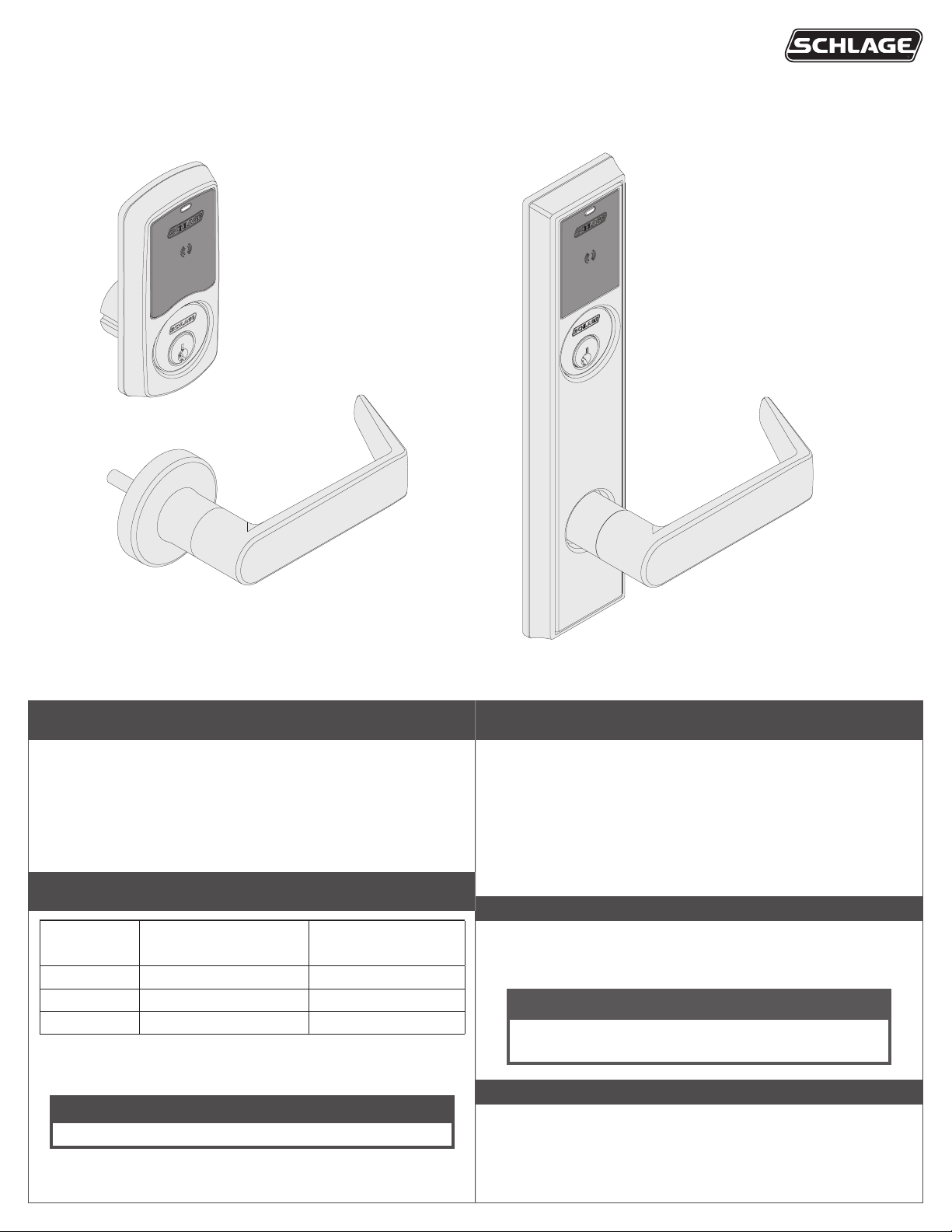
Sectional Trim
Greenwich (GRW)
Table of Contents
Prepare for Installation 2
Sectional Trim Installation 3
Escutcheon Trim Installation 6
User Guide 9
Troubleshooting 12
Compatible Cylinder Measurements
Door
Thickness
1C\v" 1Z\v" (without spring) 1Z\x"
2"
2Z\v" 1Z\x" 1C\v" (with spring)
If your cylinder measurements are not compatible,
Minimum Cylinder
Length
1C\," (without spring) 1B\,"
contact Customer Service for assistance.
Maximum Cylinder
Length
Customer Service
1-877-671-7011 www.allegion.com/us
Escutcheon Trim
Addison (ADD)
Installation Preparation
Tools Needed
• #1 and #2 Phillips screwdriver
• Lever installation tool (included
in box)
• Needle-nose pliers
Optional
• Drill with 3/8” drill bit
• Tamper-proof Torx drivers
Door preparation:
Contact Product Support at
1-877-671-7011.
IMPORTANT NOTES
All images shown in the manual show RH installation.
Do NOT use impact driver to install product.
Install and test lock with door open to avoid being locked out!
NOTICE
Notices indicate a condition that may cause equipment or
property damage only.
ENGAGE™ WEB & MOBILE APPLICATIONS
Search for “Allegion ENGAGE” in the Apple App Store or Google
Play store to download the app.
Navigate to portal.allegionengage.com to access your account
online.
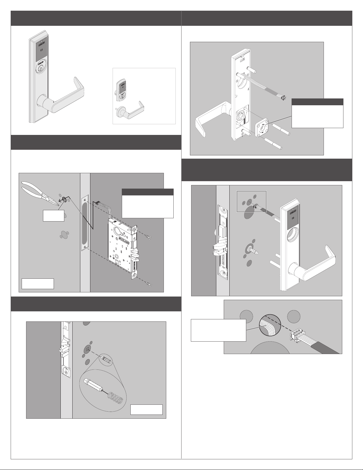
A Adjust door handing if needed.
RX (request to exit) utilizes a microswitch inside the lock case to detect
rotation of the inside knob/lever.
The RX is a removable module located on the bottom edge of the lock
chassis. The module must be properly positioned to detect inside knob/
lever rotation. If not properly positioned, the lock and/or microswitch may
be damaged.
LH
Left Hand
INSIDE
OUTSIDE
INSIDE
RH
Right Hand
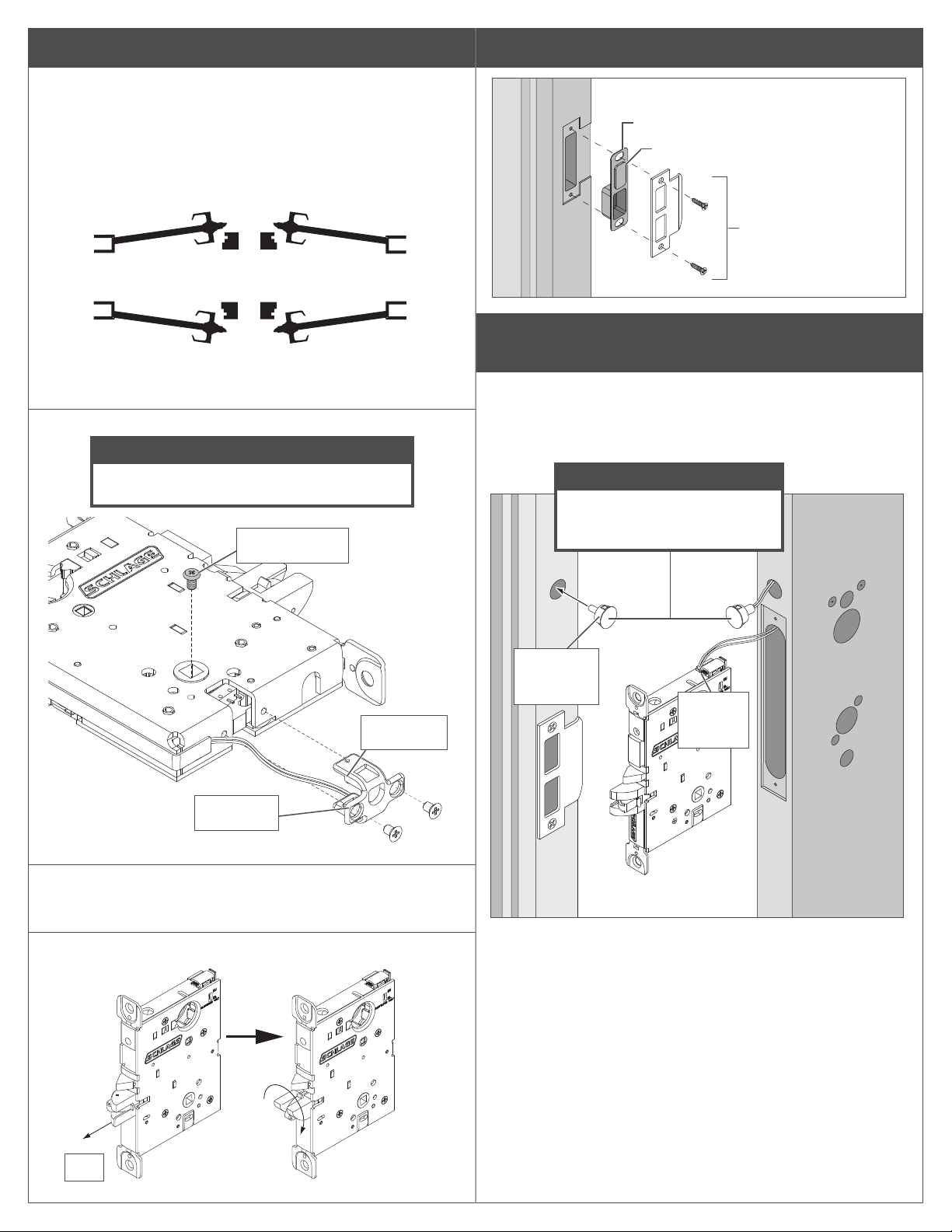
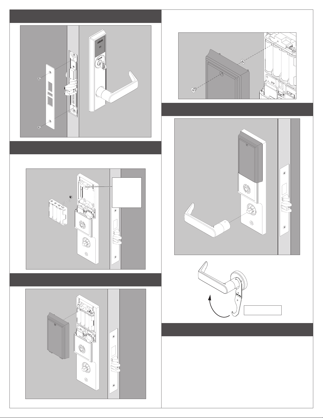
B Install strike.
DPS strike box
Magnet (for non-deadbolt models only)
Deadbolt (LEMD) models will not have a
DPS magnet
Strike
(10-136 shown)
LRB
Left Hand
Reverse Bevel
If Handing screw is NOT on the INSIDE of door follow A1 and A2 steps.
OUTSIDE
Reverse Bevel
RRB
Right Hand
A1 Remove the RX module and handing screw.
NOTICE
Handing screw and micoroswitch must be on
the INSIDE of the door.
Handing screw
Microswitch
C Deadbolt (LEMD) Only: Install door position switch and
magnet.
Feed the wires from the connector on the door position switch into the
long angled hole in the door. Plug the connector into the chassis. Do not
push in switch all the way, leave a little slack until the chassis is installed
after step 1.
NOTICE
Make sure the door position
magnet in the jamb is aligned
with the switch in the door edge!
Insert
magnet into
door jamb
Connect
cable to
chassis
Image
shows RH
installation.
RX module
A2 Reinstall the handing screw onto the inside of door, then
reinstall RX module with the microswitch also on the inside
of the door.
A3 Rotate the latch 180° (if necessary).
180˚
Pull
2

Installation Instructions for Sectional Trim
Continue for installation instructions
for your lock with sectional trim
(Greenwich).
For escutcheon
(Addison) trim
instructions go
to page 6.
3 Install spring cage into lever.
Use pliers carefully to install mounting posts to avoid damage.
IMPORTANT
Arrows in direction of
lever down rotation.
1 Install chassis.
Route chassis connector through the upper 5/8” hole on the interior side
of the door, and pull through the slack as you slide chassis into mortise.
You may use needle-nose pliers to gently pull the cable through the hole.
CAUTION
Start screws but
don’t fully tighten
Hole
INTERIOR
until Step 12!
Fully tighten mounting
posts on screws.
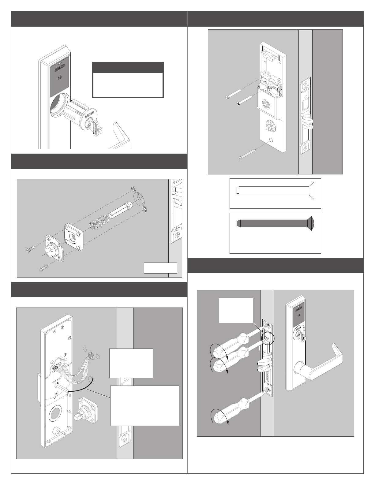
4 Install outside lever.
EXTERIOR
5 Install the outside trim and route wire all the way through
the hole to the interior side of door.
2 Install lever spindle on the exterior side of the door.
Install spring on lever spindle.
EXTERIOR
EXTERIOR
Route wire from
outside trim above
wire from the chassis.
3
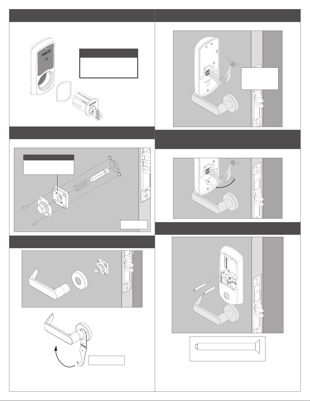
6 Partly install the key cylinder.
Turn key cylinder into the chassis. Tighten just enough to secure outside
trim. Insert key, then pull out one notch to aid with turning.
NOTICE
Do not tighten more than
six full turns! Tighten
fully at step 12!
9 Connect the cables to the inside assembly.
There are two cables that need to be connected.
Cable slack
should be folded
downward.
7 Install inside spindle, spring cage, and mounting plate.
Arrow on the mounting plate faces in direction of lever down rotation.
NOTICE
Arrows in direction of
lever down rotation.
INTERIOR
8 Install the inside rose and lever.
10 Deadbolt (LEMD) Only: Align driver bar into the
chassis.
Thumbturn should be vertical when deadbolt is retracted.
11 Install the inside assembly.
*included in box
4
Actual Size
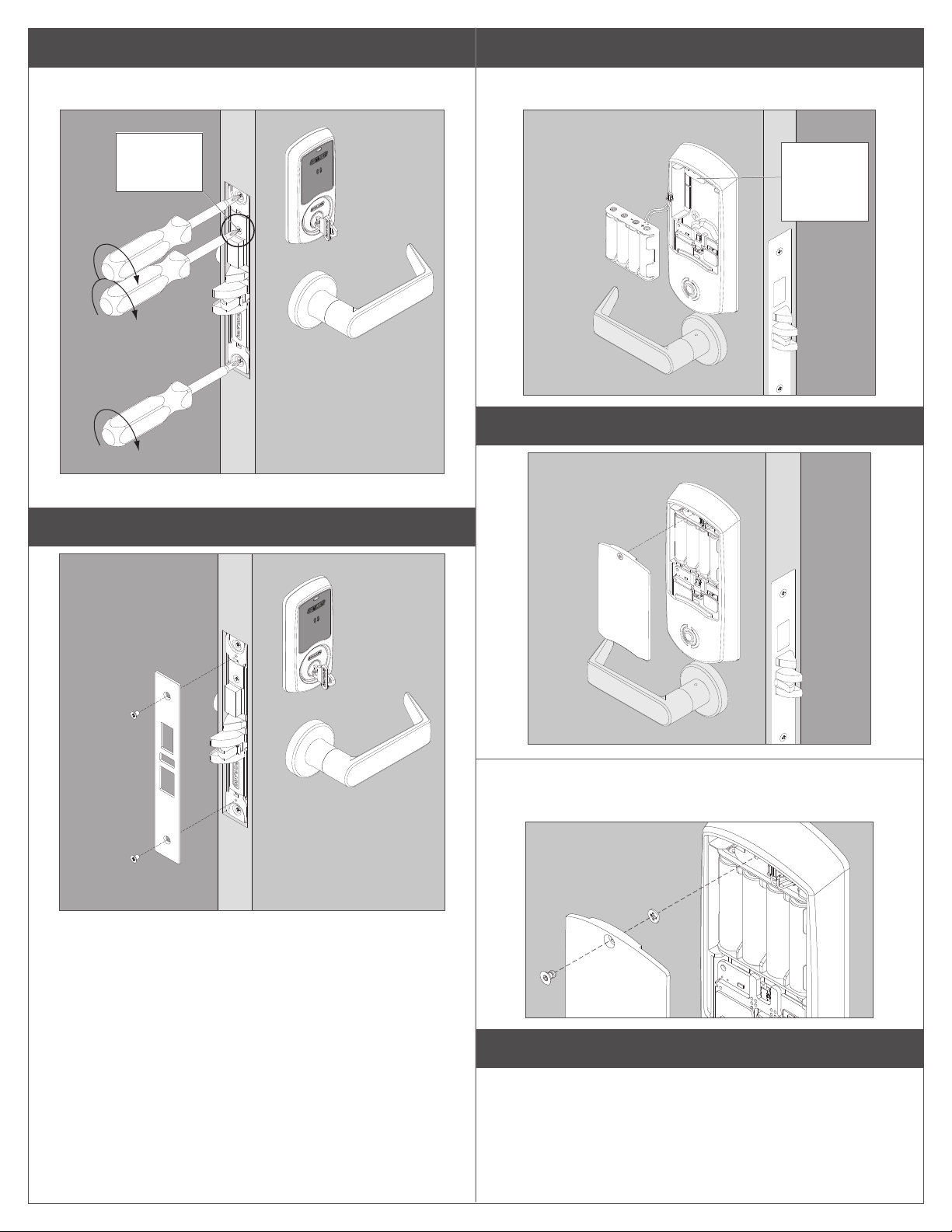
12 Fully tighten the key cylinder and chassis screws.
The cylinder face needs to be ush to the outside escutcheon. Tighten
the cylinder mounting screw.
14 Connect the battery cable.
Install four (4) AA batteries into the battery holder. Tuck the cable behind
the tab in the escutcheon.
Cylinder
mounting
screw
13 Install the armor plate.
After holder
is installed,
tuck cable
behind tab.
15 Install the battery cover and tighten the screw.
15a Optional: Install security screw and washer.
Remove standard screw and washer and replace with security screw
and washer.
16 Continue to User Guide.
Go to page 9 for information for programming your lock.
5
Installation Instructions for Escutcheon Trim
Continue for installation instructions for
your lock with escutcheon (Addison)
trim.
For sectional
(Greenwich) trim
instructions go
to page 3.
1 Install chassis.
Route chassis connector through the upper 5/8” hole on the interior side
of the door, and pull through the slack as you slide chassis into mortise.
You may use needle-nose pliers to gently pull the cable through the hole.
3 Install mounting posts and spring cage.
Arrows on the spring cage points in direction of lever down rotation. Use
pliers to carefully install mounting posts to avoid damage.
NOTICE
Arrows in direction
of lever down
rotation.
4 Install the outside trim and route wire all the way through
the hole to the interior side of door.
NOTICE
Start screws but
don’t fully tighten
Hole
INTERIOR
until Step 9!
2 Install lever spindle on the exterior side of the door.
Install spring on lever spindle.
Route wire from
outside trim above
wire from the chassis.
EXTERIOR
6
5 Partly install the key cylinder.
Turn key cylinder into the chassis. Tighten just enough to secure outside
trim. Insert key, then pull out one notch to aid with turning.
NOTICE
Do not tighten more than
six full turns! Tighten
fully at step 9!
6 Install inside spindle, spring cage, and mounting plate.
Arrows on the spring cage point in direction of lever down rotation.
8 Install the inside assembly.
7 Connect the cables to the inside assembly
There are two cables that need to be connected.
Cable slack
should
be folded
downward.
INTERIOR
Actual Size (2 mounting screws)
Actual Size (bottom screw)
Phillips or T-25 security screw
Black nish
9 Fully tighten the key cylinder and chassis screws.
The cylinder face needs to be ush to the outside escutcheon. Tighten
the cylinder mounting screw.
Cylinder
mounting
screw
For deadbolt only:
Align driver bar into the
chassis. Thumbturn must
be vertical when deadbolt
is retracted.
7
10 Install the armor plate.
11 Connect the battery cable.
Install four (4) AA batteries into the battery holder. Tuck the cable behind
the tab in the escutcheon
12a Optional: Install security screw and washer.
Remove standard screw and washer and replace with security screw
and washer.
13 Install the inside lever.
After holder
is installed,
tuck cable
behind tab.
12 Install the battery cover and tighten the screw.
*included in box
14 Continue to User Guide.
Go to page 9 for information for programming your lock.
8
L Note: The reader activates when it detects the user’s hand
holding the credential, so functionality may seem dierent than
a powered wall-mounting reader.
User Guide
2b Present credential to enroll for access.
The LED will blink green ve times and beep if successful.
2c To enroll more credentials, repeat steps 2a and 2b.
Automatic Lock Testing
Power On Self Test (POST)
The POST is a self-diagnostic test that the lock runs to verify that the
lock is installed correctly. The POST takes approximately 30 seconds
after batteries are installed. During the POST, a series of audible beeps
and LED ashes will occur. If the POST detects an issue, the test will
conclude with three red ashes of the outside LED. Once commissioned
with the ENGAGE mobile app, any issues identied during POST can be
viewed under the View Activity menu.
Standalone/Construction Access Mode
NOTICE
Standalone/Construction Access Mode is NOT required to
operate the lock!
Skip this section and proceed to “Getting Started with the ENGAGE™
Mobile Application” to commission the lock and begin using the
ENGAGE cloud-based web and mobile applications to congure lock
settings, manage user access, and view audits and alerts.
Standalone/Construction Access Mode requires an electronic credential.
• Enabled by default and after a Factory Default Reset (FDR).
• The lock will remain in Standalone/Construction Access Mode until
the mode is cancelled as described below.
• No audits are captured while the lock is in Standalone/
Construction Access Mode.
L Once enabled, Standalone/Construction Access Mode requires a
factory default reset to exit this mode and allow commissioning
with the ENGAGE mobile application.
1 Create the Master Programming Credential.
The rst card presented to a new lock while turning the inside lever
automatically becomes the Master Programming Credential. The Master
Programming Credential will not grant access. It is used only to add
additional credentials.
L Use the same Master Programming Credential for all the locks
in the facility.
1a Turn and hold down the inside lever and present to the LE
reader the card you want to make the Master Programming
Credential.
The reader LED will blink ve times for successful enrollment of Master
Programming Credential.
NOTICE
Do NOT lose the Master Programming Credential.
If lost, reset the lock to factory settings.
WARNING
If the rst card presented to a new lock to create the Master
Programming Credential is not accepted, the lock has either been
programmed or already has a Master Programming Credential.
2 Enroll user construction credentials.
3 Remove user construction credentials.
The only way to remove credentials from Standalone/Construction
Access Mode is to perform a Factory Default Reset (FDR) on the lock
and re-enter Standalone/Construction Access Mode by creating a new
Master Programming Credential and re-enrolling the other credentials.
Getting Started with the ENGAGE™ Mobile Application
ENGAGE cloud-based web and mobile applications make it easy to
congure lock settings, manage user access and view audits and alerts
from anywhere.
Your new LE wireless lock can be connected to your Wi-Fi network to
receive updates automatically overnight or can be updated anytime from
the ENGAGE mobile application when within Bluetooth range.
Download the ENGAGE mobile application
Search for “Allegion ENGAGE” on the App Store (iOS) or Google Play
Store (Android) to download the free ENGAGE mobile application.
The ENGAGE app is compatible with iPhone 4S and newer models
running iOS 9 or newer. Android devices require Android Kitkat 4.4 or
newer.
Register a new ENGAGE account
An account is required to use the ENGAGE cloud-based web and mobile
tools.
Register for an ENGAGE account in the mobile app by selecting the
“Create an Account” button from the sign in screen. You can also register
for a new account on the web at https://portal.allegionengage.com/
signup
New account registration requires a valid email address, secure
password, First and Last Name, and Site Name (for example, the
business name where the locks will reside).
Note that the password must be at least 10 characters in length and
contain three of the following: lower case letters (a-z), uppercase letters
(A-Z), numbers (0-9) and special characters (e.g., !@#$%^&*). No more
than two identical characters in a row can be used.
Select “Register” (in the mobile app) or “Sign-Up” (on the web) upon
completing all of the required information. After registering for a new
account, you will receive a verication email. You must click on the link
in the message to verify your account. This is required to keep your
account active.
Commission a lock
To manage your LE-series lock with the ENGAGE cloud-based web and
mobile applications, it must be commissioned with the ENGAGE app.
L Before commissioning, the lock must be fully assembled with the
batteries installed and the battery connector plugged in. The battery
cover MUST be installed.
NOTICE
If the lock has been put into Standalone/Construction Access
Mode, a Factory Default Reset (FDR) will need to be performed
(see Factory Default Reset).
2a Present the Master Programming Credential.
The reader LED will shine steady for twenty seconds. If no credentials
are presented during this time, the lock will leave construction enrollment
mode and return to Standalone/Construction Access Mode.
1. Sign in to the ENGAGE mobile app.
2. iOS: Select “Connect” from the tab bar at the bottom of the screen.
Android: Select “Connect to Devices” from the menu.
9

3. Select the “+” icon in the upper right corner.
4. Follow the lock commissioning wizard to complete initial setup of
the lock.
Locks can be commissioned as new, from a previously created prole,
or cloned from an existing lock in your site. Upon selecting from these
options (described below), the LED on the outside of the lock will begin
blinking red to indicate connectivity with the app.
• Select “Add New” to commission the lock with new conguration
and access rights. This is the most common scenario when
commissioning a lock.
• Select a lock from the clone list to give the lock the same
conguration and access rights as another lock you’ve already
commissioned on your site.
If you’re unsure which option to choose, select “Add New.”
Congure Wi-Fi
Your LE-series wireless lock can be connected to a Wi-Fi network to
receive updates from the ENGAGE cloud automatically, overnight.
Prior to conguring the Wi-Fi connection settings for your lock, consider
contacting your network administrator to obtain the SSID, security type,
password, and in some higher security congurations, the user ID.
Wi-Fi conguration can be set in the lock during the commissioning
process or any time while connected to the lock from the “Connect” (iOS)
or “Connect to Locks” (Android) menu.
1. Connect to the lock.
The lock must be within approximately 50 feet of your mobile
device.
2. Select “Wi-Fi.”
3. From the Wi-Fi menu, toggle Wi-Fi on.
a. Enter Wi-Fi SSID.
b. Choose the correct security protocol.
c. Enter the username (for WPA-Enterprise security only).
d. Enter the password.
e. Select “Finish” or “Save.”
L For applications using WPA-Enterprise (PEAP) security protocol,
a unique user name and password (common across all LE-series
locks) is recommended.
Upon completing Wi-Fi set-up, the lock will turn on its Wi-Fi and attempt to
connect to the network, indicated by a ashing amber LED on the reader.
L Do not attempt to guess Wi-Fi conguration details. Prior to
conguring the Wi-Fi connection settings for your lock, conrm
conguration details with your network administrator.
Add a user (credential holder) to the cloud database and
enroll a credential
The rst step in granting access rights for a user to a lock is to create
a prole and enroll a credential for them in the ENGAGE cloud database.
1. iOS: Select “Users” from the tab bar at the bottom of the screen.
Android: Select “Manage Users” from the menu.
2. Select the “+” icon in the upper right corner.
3. Enter the new user’s rst name and last name.
4. Select “Credentials” from the menu.
5. Select the “+” icon in the upper right corner.
6. Select the device you want to use to enroll the credential (any
commissioned LE-series lock can be used as an enrollment reader).
7. When the Credentials detail screen displays, present the credential
to the reader. (You will have 10 seconds to present the credential).
The mobile app will show that the credential was received, and it
will be given a name based on the order it was added to the user
record (for example: Credential 1, Credential 2, etc.).
8. Select the Credential Type (the default is “Normal”).
• Normal: Unlocks the lock momentarily (with a specied relock
delay period).
• Toggle: Changes the state of the lock from locked to unlocked, or
vice versa.
• Freeze: Freezes the lock in the current state. Lock remains frozen
until Freeze credential is presented again. Disables all other
credentials except for Pass Through.
• Pass Through: Unlocks a lock momentarily, regardless of state.
Overrides a lock in Freeze and Lock Down states.
• Lock Down: Changes the state of the lock to locked and disables
all credentials except for Pass Through and Freeze. Present a
Freeze to return lock to normal state.
• One Time Use: Allows only one Normal access per assigned lock.
• Block: Denies access to the lock and records the access attempt
as an audit.
9. Select “Save”.
Upon successfully completing these steps, a new user will be created
with a credential enrolled to them in the ENGAGE cloud database.
The new user does NOT yet have access to any locks.
Grant a user access rights to locks in the cloud database
The next step in granting access rights for a user to a lock is to assign
access rights to locks in the ENGAGE cloud database.
1. iOS: Select “Users” from the tab bar at the bottom of the screen.
Android: Select: “Manage Users” from the menu.
2. Select the desired user.
3. Under “Manage Access,” select “Locks.”
4. Select the locks you wish to assign the user access to.
Selected locks will have a check mark.
5. Select “Save” or “Done.”
Upon successfully completing these steps, a user will be granted access
rights to locks in the ENGAGE cloud database. The lock must be
updated for the change to take eect.
Send updates to user access rights to the lock
If the lock has been congured to connect to a Wi-Fi network, it will
automatically update overnight.
If the lock has not been congured to connect to a Wi-Fi network, or if
the update is urgent, connect to the lock with the ENGAGE app to send
the update.
Bluetooth must be enabled on your device and you must be within
approximately 50 feet of the lock to connect.
1. iOS: Select “Connect” from the tab bar at the bottom of the screen.
Android: Select “Connect to Locks” from the menu.
2. Select the desired lock.
3. Select “Update Door File.”
Upon successfully completing these steps, the lock will be updated with
the latest user access rights and the audit history will be uploaded to the
ENGAGE cloud database.
10

View lock audit information
Audit information for each lock can be viewed from anywhere with the
ENGAGE mobile app.
Audit information is stored and viewed from the ENGAGE cloud
database. If the lock has been congured to connect to the Wi-Fi
network, audit information will be uploaded to the ENGAGE cloud
database daily. If the lock has not been congured to connect to a Wi-Fi
network, you must rst connect to the lock with the ENGAGE mobile app
and select “Update Door File” or “Get Audits.”
1. iOS: Select “Devices” from the tab bar at the bottom of the screen.
Android: Select “Manage Devices” from the menu.
2. Select the desired lock.
3. Under “Device Audits,” select “Display Activity.”
L To see basic information related to access history, use the Activity
view. To view the results of the built in diagnostic test or for
troubleshooting related to Wi-Fi connectivity or other issues, use the
Diagnostics view.
Invite others to assist with administrative duties for
your site
1. iOS: Select “My Team” from the tab bar.
Android: Select “My Team” from the menu.
2. Select the “+” icon in the upper right corner.
3. Enter the email address, rst name, last name and role of the
person you wish to invite.
• Administrator: The most trusted administrative access role. The
Administrator can perform all duties within the ENGAGE web and
mobile applications.
• Manager: Same administrative privileges as an Administrator but
cannot invite or remove other Managers or Administrators.
• Operator: The most limited access. An operator can only connect
to locks to send updates or perform diagnostics.
4. Select “Save.”
Factory Default Reset (FDR)
A Factory Default Reset (FDR) will return the LE-series lock settings
to the original settings as shipped from the factory. Removes
congurations, databases, and requires the lock to be re-captured. A
FDR will not remove the lock from your ENGAGE account.
A Press and hold the FDR button for ve seconds.
Safe Mode
NOTICE
Enter Safe Mode only as a last resort! Entering Safe Mode
causes the lock to load a special version of rmware
intended to be immediately updated. Once in safe mode,
commission the lock with the ENGAGE mobile application
and perform a rmware update.
To put the lock in Safe Mode:
1. Remove power from the lock.
2. Turn the inside lever 2 times.
3. Apply power to the lock.
4. When the LED inside the battery cover begins to blink, turn and
hold the inside lever.
5. Press the FDR button 3 times to begin Safe Mode process.
The lock will not perform the Safe Mode process if the above
sequence is not completed within 10 seconds.
Lock Indicator Guide
Indicators Meaning
Fast ash green x5 Construction Access Mode:
Steady green until
timeout (20 seconds)
Long ash red x2 Manual/Construction Mode: Timed
Flash red x9 followed
by the respective
credentials indication
Flash green x1 +
beep, then ash red
x1 upon relock
Flash green x2 +
beep
Successful creation of master or
user construction credential.
Construction Access Mode: Waiting
for credential after presentation of
master construction credential.
out to construction mode.
Low battery.
Access granted.
Already unlocked.
The LED will blink green two times and beep two times.
B Turn the inside lever three times within 20 seconds.
LED will blink red and lock will beep with each turn.
C Reinstall battery cover, then use the app to capture
your lock.
Turn the inside lever. The LE will communicate on BLE looking for your
mobile device for two minutes after each lever turn in FDR mode.
If you have used this LE in Construction Access Mode, you must
complete a FDR before it will communicate on BLE.
Flash red x12 + beep In secure privacy/lockdown mode.
Flash red x1 + beep Access denied
Flash alternate greenred x5 + beep
Flash red x4 + beep Access denied. Outside credential
Flash red x1 per
second
Fast ash green x3 +
fast beep x3
Fast ash red x3 Power O self test - Fail.
Freeze/Lockdown mode.
schedule.
BLE communicating.
Power On self test - Pass.
11

Problem Possible Cause Action
Lever droops, is slow, or fails to fully
return to horizontal position.
Troubleshooting
• Spring cage is backward.
• Spring cage is assembled incorrectly.
• Remove the lever and reassemble with the spring
cage arrow in the direction of lever down rotation,
see page 3 (sectional) or 6 (escutcheon).
No beeps or blinks when battery
pack is connected.
Batteries are hot. • Wires are pinched or shorted.
Fails POST. There are no three
green LED blinks and beeps at the
end of power up, just three red LED
blinks with beeps.
Fails POST with three red blinks and
the LE is unlocked.
• No power.
• Improper plug connection.
• Pinched wires or bent connector pins.
• Reversed battery or dead battery.
• A battery is reversed.
• Motor not connected.
• Battery voltage low.
• Ribbon cables are not connected.
• Motor failed to lock with rst power up, LE
outside lever stayed unlocked.
• Check batteries are inserted correctly.
• Check all wiring and connectors (battery
connector, two connectors on back of inside trim).
• Check that the new battery voltage is 6 Volts DC
or more.
• Look for pinched and shorted wires.
• Replace all batteries with a new set of 4 AA
alkaline batteries. Hot batteries will soon start
leaking.
• Make sure the battery polarity is per the battery
pack markings. Measure the new battery voltage
as 6 Volts DC or more to conrm proper insertion.
• Inspect for cut or pinched through door wires.
• Check wires connections on the back of the inside
escutcheon, the wires on the top of mortise case
motor connection, and the wires on the bottom of
lock case switch connections.
• Measure battery voltage, the voltage must be
over 6 Volts DC with new batteries and have the
correct insertion polarity.
• Check motor wire connection on the top of the
lock mortise case.
• Check motor wire plug up on the back of the
inside trim.
• Look for connector pins that might be bent or
broken, check for cut or broken wire.
After power up the outside lever is
not secure and the inside lever is
locked, will not turn.
Unable to connect to the device with
ENGAGE mobile Bluetooth.
Don’t see the expected “Schlage
Lock” in the nearby list.
Cannot do a Factory Default Reset
(FDR). There were no three beeps
with the inside lever.
Programmed credentials that once
worked are now denied.
• The mortise case handing is incorrect. • The mortise case handing screw and RX module
must be positioned to the inside of the door. See
step A1 on page 2.
• Must be in FDR mode to see "Schlage
Lock."
• The battery cover must be installed to avoid
Tamper Mode before Bluetooth will work.
• RX switch has wrong handing.
• RX cable is disconnected or pins are bent on
back of inside escutcheon.
• Wire is cut on the RX cable.
• Activation dates conict because the lock
has the wrong time and date. The lock time
and date can be wrong after a long period of
no power.
• Press “+” in the ENGAGE mobile app. FDR
locks are found in "+" ADD before they are
commissioned.
• Tighten the lock battery cover.
• Turn and release the inside lever of the lock. In
FDR mode it will beep with each turn.
• If the lock is in Construction Mode, FDR it to reset
for commissioning.
• To refresh the "ADD" list in the app, swipe your
nger down the "+" screen.
• Check and correctly hand the mortise case RX
switch. The handing screw and RX switch must
both be on the inside of the mortise. See step A3
on page 2.
• Disassemble and inspect the ribbon cable on the
back of the inside trim.
• Repair or replace the mortise lock RX switch
module assembly.
• Set the real time clock by connecting with
ENGAGE app. If the lock is connected to Wi-Fi, a
Wi-Fi call in by the lock also sets the correct lock
time and date.
• Check the battery connections and install new
batteries if necessary before setting the correct
time and date.
12

Problem Possible Cause Action
No Wi-Fi connection (Network AP
association failed).
Long time period of amber LED
blinks.
• Wi-Fi conguration in the lock is wrong.
• Wi-Fi is out of range at the lock location.
• Wi-Fi mandatory data rate is too high.
• Conrm, reenter, and "save" the Wi-Fi
conguration for the lock location.
• You must have the correct SID, Security type,
Password, and also for WPA2(PEAP) a User ID.
• Conrm the signal availability by entering the
SSID and password (ID) on your mobile device
to connect with Wi-Fi at the door. A mobile app
Wi-Fi analyzer can also indicate signal strength. If
the Wi-Fi signal is too weak reassign the lock to a
closer wireless router, or add a Wi-Fi router closer
to the lock.
• Set the Wi-Fi router maximum Wi-Fi mandatory
data rate to 24 Mbps or less.
Reader does not respond to
credentials (no beeps or LEDs) but
lock passed POST.
• With low batteries the reader “beep and
read” is the rst function to stop.
• Lock did not detect a card was presented.
• Lock is not detecting a user in the area
around the reader.
FCC Statement
This equipment has been tested and found to comply with the limits for a Class B digital
device, pursuant to Part 15 of the FCC Rules. These limits are designed to provide
reasonable protection against harmful interference in a residential installation. This
equipment generates, uses, and can radiate radio frequency energy and, if not installed
and used in accordance with the instructions, may cause harmful interference to radio
communication. However, there is no guarantee that interference will not occur in a
particular installation. If this equipment does cause harmful interference to radio or
television reception, which can be determined by turning the equipment o and on, the
user is encouraged to try to correct the interference by one of the following measures:
Reorient or relocate the receiving antenna.
Increase the separation between the equipment and receiver.
Connect the equipment into an outlet on a circuit dierent from that to
which the receiver is connected.
Consult the dealer or an experienced radio/TV technician for help.
FCC Caution: Any changes or modications not expressly approved by the party
responsible for compliance could void the user’s authority to operate this equipment.
This device complies with Part 15 of the FCC Rules. Operation is subject to the following
two conditions: (1) This device may not cause harmful interference, and (2) this device
must accept any interference received, including interference that may cause undesired
operation.
FCC Radiation Exposure Statement
To comply with FCC/IC RF exposure requirements for mobile transmitting devices, this
transmitter should only be used or installed at locations where there is at least 20 cm
separation distance between the antenna and all persons.
Industry Canada Statement
Under Industry Canada regulations, this radio transmitter may only operate using an
antenna of a type and maximum (or lesser) gain approved for the transmitter by Industry
Canada. To reduce potential radio interference to other users, the antenna type and its
gain should be so chosen that the equivalent isotropically radiated power (e.i.r.p.) is not
more than that permitted for successful communication.
Industrie Canada Déclaration
Conformément à la réglementation d’Industrie Canada, le présent émetteur radio peut
fonctionner avec une antenne d’un type et d’un gain maximal (ou inférieur) approuvé
pour l’émetteur par Industrie Canada. Dans le but de réduire les risques de brouillage
radioélectrique à l’intention des autres utilisateurs, il faut choisir le type d’antenne et son
gain de sorte que la puissance isotrope rayonnée équivalente (p.i.r.e.) ne dépasse pas
l’intensité nécessaire à l’établissement d’une communication satisfaisante.
Industry Canada Radiation Exposure Statement
This Device complies with Industry Canada License-exempt RSS standard(s). Operation
is subject to the following two conditions: (1) this device may not cause interference,
and (2) this device must accept any interference, including interference that may cause
undesired operation of the device.
Industrie Canada l’exposition aux radiations
Le présent appareil est conforme aux CNR d’Industrie Canada applicables aux appareils
radio exempts de licence. L’exploitation est autorisée aux deux conditions
suivantes : (1) l’appareil ne doit pas produire de brouillage, et (2) l’appareil doit
accepter tout brouillage radioélectrique subi, même si le brouillage est susceptible d’en
compromettre le fonctionnement.
• Check the batteries and replace if necessary. The
reader function stops with low batteries (4.6 Volts
DC or less).
• Credentials should be presented by hand directly
over the Schlage logo on the center front of the
reader. Place the card on the plastic of the lock.
• Avoid interference from lanyards, wallets, or
purses.
UL Statements
• Outside lever is normally locked. Inside lever always allows egress.
• Unit shall not interfere with the operation of Panic Hardware.
• Wireless communications, Wi-Fi, Bluetooth, Door Position, and Request to
Exit switch features are not part of UL Listed product.
• Tested to compliance with UL 294 5th Edition Class I.
• Tested to compliance with UL 294 6th Edition.
• Tested to compliance with CAN/ULC-S319-05, Class I.
• Access Control Performance Levels
Destructive Attack Line Security Endurance Standby Power
IV I IV I
Customer Service
1-877-671-7011 www.allegion.com/us
© Allegion 2017
Printed in U.S.A.
P518-027 Rev. 01/17-b

Cerradura de la serie LE
Serrure de la gamme LE
Modelo LE
Modèle LE
Instrucciones de instalación y guía del usuario
Instructions d’installation et manuel de l’utilisateur
Moldura seccional
Chant sectionnel
Greenwich (GRW)
Índice
Table des matières
Preparación de la instalación
Préparation de l’installation
Instrucciones de instalación para la moldura seccional
Instructions d’installation pour le chant sectionnel
Instrucciones de instalación para la moldura de rosetón
Instructions d’installation pour le chant à écusson
Guía del usuario
Manuel de l’utilisateur
Resolución de problemas
Dépannage
15
17
20
23
29
30
Moldura de rosetón
Chant à écusson
Addison (ADD)
Aplicaciones Web y Móvil ENGAGE™
Applications Web et Mobiles ENGAGE
Busque “Allegion ENGAGE” en el Apple App Store o Google
Play Store para descargar la aplicación. Navegue hasta portal.
allegionengage.com para acceder a su cuenta en línea.
Cherchez « Allegion ENGAGE » dans l’App Store d’Apple ou
Google Play pour télécharger l’application. Rendez-vous sur
portal.allegionengage.com an d’accéder à votre compte en ligne.
Servicio al cliente Service à la clientèle
1-877-671-7011 www.allegion.com/us
MC
14

Mediciones de cilindro compatible
Mesures des barillets compatibles
Espesor de
la puerta
Épaisseur de
la porte
1C\v" 1Z\v" (sin resorte/sans ressort) 1Z\x"
2"
2Z\v" 1Z\x"
Si sus mediciones de cilindro no son compatibles, póngase en
contacto con el Servicio de atención al cliente para obtener ayuda.
Si les mesures de votre barillet ne sont pas compatibles, contactez
le service à la clientèle pour obtenir de l’aide.
Longitud mínima del
cilindro
Longueur minimale du
barillet
1C\," (sin resorte/sans ressort) 1B\,"
Longitud máxima
del cilindro
Longueur maximale
du barillet
1C\v" (con resorte/ avec
ressort)
Preparación de la instalación
A Ajuste la orientación de la puerta si es necesario.
Ajustez le sens d’ouverture de la porte au besoin.
RX (solicitud de salida) utiliza un microinterruptor dentro de la caja de
la cerradura para detectar la rotación de la perilla/palanca interior. El
RX es un módulo desmontable situado en el borde inferior del chasis
de la cerradura. El módulo debe estar posicionado adecuadamente
para detectar la rotación de la perilla/palanca interior. Si no se coloca
correctamente, la cerradura o el microinterruptor puede verse sometidos
a daños.
Le module RX (pour « request to exit ») utilise un micro-commutateur logé
à l’intérieur du boîtier de la serrure, servant à détecter la rotation de la
poignée ou du levier intérieur. Le RX est un module amovible situé dans
le bas du caisson de la serrure. Pour détecter la rotation de la poignée
ou du levier intérieur, le module doit être correctement placé. Si non, la
serrure, le micro-commutateur ou les deux risquent d’être endommagés.
LH
manija a la izquierda
ouverture par la gauche
INTERIOR/INTÉRIEUR
manija a la derecha
ouverture par la droite
RH
Préparation de l’installation
Herramientas necesarias
Outils nécessaires
• Destornillador Phillips n.° 1 y 2
Tournevis cruciformes nº 1 et 2
• Herramienta de instalación de
palanca (incluida en la caja)
Outil d’installation du levier (inclus
dans l’emballage)
• Alicates de punta na
Pince à bec elé
Preparación de la puerta / Préparation de la porte :
Póngase en contacto con soporte técnico al:
Contactez l’assistance technique au :
Opcional
En option
• Taladro con broca de 3/8”
Perceuse avec foret de
0,95 cm (3/8 po)
• Destornilladores Torx a
prueba de manipulaciones
indebidas
Tournevis Torx de sécurité
1-877-671-7011
NOTAS IMPORTANTES
REMARQUES IMPORTANTES
NO utilice un destornillador de impacto para instalar el producto.
N’utilisez PAS de tournevis à percussion.
¡Instale y pruebe la cerradura con la puerta abierta para evitar quedarse afuera!
Installez la serrure et faites un essai en maintenant la porte ouverte pour
éviter d’être coincé à l’extérieur!
Todas las imágenes que se muestran en el manual evidencian la
instalación a mano derecha.
Toutes les images dans le manuel indiquent l’installation RH.
OUTSIDE/EXTÉRIEUR
INTERIOR/INTÉRIEUR
LRB
manija a la izquierda
ouverture par la gauche
Bisel inverso
Pêne à main inversée
OUTSIDE/EXTÉRIEUR
manija a la derecha
ouverture par la droite
Pêne à main inversée
RRB
Bisel inverso
Si el tornillo de la manija NO está en el INTERIOR de la puerta, siga los
pasos A1 y A2.
Si la vis manuelle N’EST pas à l’INTÉRIEUR de la porte suivez les
étapes A1 et A2.
A1 Retire el módulo de RX y el tornillo de la manija.
Retirez le module RX et la vis du sens d’ouverture de la
porte.
AVISO
El tornillo de la manija y
el interruptor en miniatura
deben estar en el INTERIOR
de la puerta.
MISE EN GARDE
La vis manuelle et le
commutateur micro doivent
être à l’INTÉRIEUR de la
porte.
Tornillo de la manija
Vis du sens d’ouverture
de la porte
L Nota: El lector se activa cuando detecta la mano del usuario que
sostiene la credencial, por lo que la funcionalidad puede ser
diferente de un lector de montaje en pared con alimentación.
L Remarque : Le lecteur s’active lorsqu’il détecte les identiants
dans la main de l’utilisateur, la fonctionnalité peut alors sembler
diérente de celle d’un lecteur électrique monté au mur.
AVISO
Las precauciones indican una condición que puede causar solo
daños a los equipos o a los bienes materiales.
MISE EN GARDE
Les mises en garde indiquent des situations pouvant entraîner
des dommages aux biens ou au matériel uniquement.
La imagen
muestra la
instalación a
mano derecha.
L’image indique
l’installation RH.
Microinterruptor
Micro-commutateur
Módulo RX
Module RX
15

A2 Vuelva a colocar el tornillo de la manija en el interior
de la puerta, vuelva a instalar el módulo RX con el
microinterruptor también en el interior de la puerta.
Remontez la vis du sens d’ouverture de la porte du côté
intérieur de la porte, puis réinstallez le module RX
avec le micro-commutateur, toujours du côté intérieur
de la porte.
A3 Gire el pestillo 180° (si es necesario).
Faites pivoter le loquet à 180° (si nécessaire).
C Cerrojo (LEMD) solamente: Instale el interruptor de
posición de la puerta y el imán.
Modèles à pêne dormant (LEMD) seulement : Montez
l’aimant et le commutateur de position de la porte.
Alimente los cables del conector en el interruptor de posición de la
puerta en el agujero en ángulo largo en la puerta. Enchufe el conector
en el chasis. No empuje el interruptor hasta el tope, deje un poco de
holgura hasta que el chasis está instalado después del paso 1.
Insérez les ls du connecteur sur le commutateur de position de la porte
dans le long trou en biais pratiqué dans la porte. Branchez le connecteur
sur la serrure. N’enfoncez pas le commutateur jusqu’au fond. Laissez un
peu de jeu jusqu’à ce que le caisson soit installé, après l’étape 1.
Tire
Tirez
B Instale el pleno.
Installez la gâche.
Imán (para modelos sin cerrojo solamente).
Los modelos con cerrojo (LEMD) no tendrán
un imán de DPS
Aimant (uniquement pour les modèles non
munis d’un pêne dormant). Les modèles à pêne
dormant (LEMD) n’ont pas d’aimant DPS.
180˚
AVISO
Asegúrese de que el imán
de posición de la puerta en
la jamba esté alineado con
el interruptor en el borde de
la puerta.
Inserte el imán en
jamba de la puerta.
Insérez l’aimant dans le
montant de la porte.
MISE EN GARDE
Assurez-vous que l’aimant de
position de la porte, dans le
montant, se trouve vis-à-vis le
commutateur dans le chant de
la porte!
Conecte el cable
al chasis.
Branchez le câble
sur le caisson.
Caja de pleno del DPS (interruptor de
posición de puerta)
Gâche encloisonnée à commutateur
de position de la porte (DPS pour
« door position switch »)
16
Pleno/Gâche
(Modelo/Modèle 10-136)

Instrucciones de instalación para la moldura seccional
Instructions d’installation pour le chant sectionnel
Continúe para ver las instrucciones de instalación
para su cerradura con moldura seccionar
(Greenwich).
Vous allez maintenant lire les instructions
d’installation d’une serrure à chant sectionnel
(Greenwich).
Para obtener
instrucciones con
respecto a la moldura
de rosetón (Addison)
vaya a la página 20.
Pour installer une
serrure à chant à
écusson (Addison),
allez à la page 20.
1 Instale el chasis.
Installez le caisson.
Tienda el conector de chasis a través del agujero de 5/8” de la parte
superior en el lado interior de la puerta, y tire a través de la holgura
mientras desliza el chasis en la caja de embutir.
Acheminez le connecteur du caisson par le trou supérieur de 1,59 cm
(5/8 po) à partir de l’intérieur de la porte et tirez le câble au fur et à
mesure que vous glissez le caisson dans la mortaise.
AVISO
Inicie la instalación de los tornillos,
pero no los apriete completamente
hasta el paso 12.
MISE EN GARDE
Commencez à serrer
les vis, mais ne le
faites pas à fond
avant l’étape 12!
3 Instale la jaula de resorte en la palanca.
Installez la cage à ressorts sur le levier.
Utilice los alicates cuidadosamente para instalar los anclajes de montaje
y evitar daños.
Avec la pince, posez les supports de montage avec soin pour éviter tout
dommage.
AVISO
Las echas en la dirección
de la rotación de la palanca
hacia abajo.
MISE EN GARDE
Les èches indiquent le
sens de rotation du levier
lorsque celui-ci est abaissé.
Apriete completamente los
anclajes de montaje en los
tornillos.
Serrez les supports de
montage jusqu’au bout sur
les vis.
4 Instale la palanca exterior.
Installez le levier extérieur.
EXTERIOR
EXTÉRIEUR
Agujero
Trou
INTERIOR
INTÉRIEUR
2 Instale el husillo de la palanca en el lado exterior de la
puerta.
Posez la tige de commande du levier depuis l’extérieur
de la porte.
Instale el resorte en el husillo de la palanca.
Montez le ressort sur la tige de commande du levier.
EXTERIOR
EXTÉRIEUR
5 Instale la moldura exterior y pase el cable a través del
agujero hacia la parte interior de la puerta.
Installez le chant extérieur et acheminez le câble par le
trou vers l’intérieur de la porte.
EXTERIOR
EXTÉRIEUR
Tienda el cable desde
la moldura exterior por
encima del cable desde el
chasis.
Faites passer le câble du
chant extérieur par-dessus
le câble du caisson.
17

6 Instale parcialmente el cilindro de la llave.
8 Instale la rosa interior y la palanca.
Installez partiellement le barillet de serrure.
Gire el cilindro de la llave en el chasis. Apriételo lo suciente para jar la
moldura exterior. Inserte la llave, luego, saque una muesca para ayudar
con el giro.
Tournez le barillet de serrure dans le caisson. Serrez juste assez pour
xer le chant extérieur. Insérez la clé, puis sortez-la d’une entaille pour
faciliter la rotation.
AVISO
¡No apriete más de seis
vueltas completas! ¡Apriete
completamente en el paso 12!
MISE EN GARDE
N’eectuez pas plus de six tours
complets pour serrer! Vous
serrerez à fond à l’étape 12!
Installez la rosette et le levier intérieurs.
*incluido en la caja
*inclus dans l’emballage
9 Conecte los cables al interior del conjunto.
Branchez les câbles sur l’assemblage intérieur.
Hay dos cables que deben conectarse.
Il y a deux câbles à raccorder.
7 Instale el husillo interior, la jaula de resortes y la placa
de montaje.
Installez la tige de commande, la cage à ressorts et la
plaque de montage intérieures.
Flecha en las caras de las placas de montaje en dirección de rotación
de la palanca hacia abajo.
La èche sur la plaque de montage indique le sens de rotation du levier
lorsque celui-ci est abaissé.
AVISO
Las echas en la dirección de
la rotación de la palanca
hacia abajo.
MISE EN GARDE
Les èches indiquent le sens
de rotation du levier lorsque
celui-ci est abaissé.
INTERIOR
INTÉRIEUR
La holgura del cable debe
doblarse hacia abajo.
Le faisceau devrait être plié
vers le bas.
10 Cerrojo (LEMD) solamente: Alinee la barra de
controlador en el chasis.
Modèles à pêne dormant (LEMD) seulement : Alignez
la tige d’entraînement dans le caisson.
El giro con pulgar debe estar en posición vertical cuando se retrae
cerrojo.
La barrette tournante devrait être verticale lorsque le pêne dormant est
rétracté.
18

11 Instale el conjunto interior.
14 Conecte el cable de la pila.
Installez l’assemblage intérieur.
Tamaño real / Taille réelle
12 Apriete completamente los tornillos del cilindro de la
llave y el chasis.
Serrez le barillet de serrure et les vis de caisson
jusqu’au bout.
La cara del cilindro debe estar al mismo nivel que el rosetón exterior.
Apriete el tornillo de montaje del cilindro.
La face du barillet doit aeurer au chant à écusson extérieur. Serrez la
vis de montage du barillet.
Connectez le câble du bloc-piles.
Instale cuatro (4) pilas AA en el compartimento de la pila. Coloque el
cable por detrás de la pestaña en el rosetón
Insérez quatre (4) piles AA dans le porte-piles. Repliez le câble derrière
la patte dans l’écusson.
Una vez instalado el
compartimento, coloque
el cable detrás de la
pestaña.
Une fois le porte-piles
monté, repliez le câble
derrière la patte.
15 Instale la tapa de las pilas y apriete el tornillo.
Montez le couvercle pour piles et serrez la vis.
Tornillo de montaje del cilindro
Vis de montage du barillet
13 Instale la placa de blindaje.
Montez la plaque de protection.
15a Opcional: Instale el tornillo y la arandela de seguridad.
En option : Posez la vis et la rondelle de sécurité.
Retire el tornillo y la arandela estándar y reemplace con el tornillo y la
arandela de seguridad.
Retirez la vis et la rondelle standards et remplacez-les par la vis et la
rondelle de sécurité.
16 Continúe a la Guía del usuario.
Lisez maintenant le manuel de l’utilisateur.
Vaya a la página 23 para obtener información sobre la programación de
su cerradura.
Allez à la page 23 pour savoir comment programmer votre serrure.
19

Instrucciones de instalación para la moldura de rosetón
3 Instale los anclajes de montaje y la jaula de resortes.
Instructions d’installation pour le chant à écusson
Continúe para ver las instrucciones de instalación
para su cerradura con moldura de rosetón
(Addison).
Vous allez maintenant lire les instructions
d’installation d’une serrure à chant à écusson
(Addison).
Para obtener
instrucciones con
respecto a la moldura
seccional (Greenwich)
vaya a la página 17.
Pour installer une
serrure à chant
sectionnel (Greenwich),
allez à la page 17.
1 Instale el chasis.
Installez le caisson.
Tienda el conector de chasis a través del agujero de 5/8” de la parte
superior en el lado interior de la puerta, y tire a través de la holgura
mientras desliza el chasis en la caja de embutir.
Acheminez le connecteur du caisson par le trou supérieur de 1,59 cm
(5/8 po) à partir de l’intérieur de la porte et tirez le câble au fur et à
mesure que vous glissez le caisson dans la mortaise.
AVISO
Inicie la instalación de los tornillos,
pero no los apriete completamente
hasta el paso 12.
MISE EN GARDE
Commencez à serrer
les vis, mais ne le
faites pas à fond
avant l’étape 12!
Installez les supports de montage et la cage à ressorts.
Las echas en los puntos de la jaula de resorte en la dirección de
rotación de la palanca hacia abajo. Utilice los alicates para instalar
cuidadosamente los anclajes de montaje y evitar daños.
Les èches sur la cage à ressorts indiquent le sens de rotation du
levier lorsque celui-ci est abaissé. Avec la pince, posez les supports de
montage avec soin pour éviter tout dommage.
AVISO
Las echas en
la dirección de
la rotación de la
palanca hacia abajo.
MISE EN GARDE
Les èches
indiquent le sens
de rotation du levier
lorsque celui-ci est
abaissé.
4 Instale la moldura exterior y pase el cable a través del
agujero hacia la parte interior de la puerta.
Installez le chant extérieur et acheminez le câble par le
trou vers l’intérieur de la porte.
Agujero
Trou
INTERIOR
INTÉRIEUR
2 Instale el husillo de la palanca en el lado exterior de la
puerta.
Posez la tige de commande du levier depuis l’extérieur
de la porte.
Instale el resorte en el husillo de la palanca.
Montez le ressort sur la tige de commande du levier.
Tienda el cable desde
la moldura exterior
por encima del cable
desde el chasis.
Faites passer le câble
du chant extérieur
par-dessus le câble
du caisson.
20
EXTERIOR
EXTÉRIEUR

5 Instale parcialmente el cilindro de la llave.
7 Conecte los cables al interior del conjunto.
Installez partiellement le barillet de serrure.
Gire el cilindro de la llave en el chasis. Apriételo lo suciente para jar la
moldura exterior. Inserte la llave, luego, saque una muesca para ayudar
con el giro.
Tournez le barillet de serrure dans le caisson. Serrez juste assez pour
xer le chant extérieur. Insérez la clé, puis sortez-la d’une entaille pour
faciliter la rotation.
AVISO
¡No apriete más de seis
vueltas completas! ¡Apriete
completamente en el paso 9!
MISE EN GARDE
N’eectuez pas plus de six tours
complets pour serrer! Vous
serrerez à fond à l’étape 9!
Branchez les câbles sur l’assemblage intérieur.
Hay dos cables que deben conectarse.
Il y a deux câbles à raccorder.
La holgura del cable debe
doblarse hacia abajo.
Le faisceau devrait être plié
vers le bas.
Para cerrojo solamente: Alinee la
barra de controlador en el chasis.
El giro con pulgar debe estar en
posición vertical cuando se retrae
cerrojo.
Pour les modèles à pêne dormant
seulement : Alignez la tige
d’entraînement dans le caisson. La
barrette tournante doit être verticale
lorsque le pêne dormant est rétracté.
8 Instale el conjunto interior.
6 Instale el husillo interior, la jaula de resortes y la placa
de montaje.
Installez la tige de commande, la cage à ressorts et la
plaque de montage intérieures.
Flecha en las caras de las placas de montaje en dirección de rotación
de la palanca hacia abajo.
La èche sur la plaque de montage indique le sens de rotation du levier
lorsque celui-ci est abaissé.
AVISO
Las echas en la dirección de
la rotación de la palanca
hacia abajo.
MISE EN GARDE
Les èches indiquent le sens
de rotation du levier lorsque
celui-ci est abaissé.
Installez l’assemblage intérieur.
Tamaño real (2 tornillos de montaje)
Taille réelle (2 vis de montage)
INTERIOR
INTÉRIEUR
Tamaño real (tornillo inferior)
Tornillo de seguridad Phillips o T-25
Acabado en negro
Taille réelle (vis inférieure)
Vis cruciforme ou T-25 de sécurité
Finition noire
21

9 Apriete completamente los tornillos del cilindro de la
llave y el chasis.
Serrez le barillet de serrure et les vis de caisson
jusqu’au bout.
La cara del cilindro debe estar al mismo nivel que el rosetón exterior.
Apriete el tornillo de montaje del cilindro.
La face du barillet doit aeurer au chant à écusson extérieur. Serrez la
vis de montage du barillet.
Tornillo de montaje
del cilindro
Vis de montage du
barillet
12 Instale la tapa de las pilas y apriete el tornillo.
Montez le couvercle pour piles et serrez la vis.
12a Opcional: Instale el tornillo y la arandela de seguridad.
En option : Posez la vis et la rondelle de sécurité.
Retire el tornillo y la arandela estándar y reemplace con el tornillo y la
arandela de seguridad.
Retirez la vis et la rondelle standards et remplacez-les par la vis et la
rondelle de sécurité.
10 Instale la placa de blindaje.
Montez la plaque de protection.
11 Conecte el cable de la pila.
Connectez le câble du bloc-piles.
Instale cuatro (4) pilas AA en el compartimento de la pila. Coloque el
cable por detrás de la pestaña en el rosetón
Insérez quatre (4) piles AA dans le porte-piles. Repliez le câble derrière
la patte dans l’écusson.
13 Instale la rosa interior y la palanca.
Installez la rosette et le levier intérieurs.
*incluido en la caja
*inclus dans
l’emballage
22
Una vez instalado el
compartimento, coloque el
cable detrás de la pestaña.
Une fois le porte-piles
monté, repliez le câble
derrière la patte.
14 Continúe a la Guía del usuario.
Lisez maintenant le manuel de l’utilisateur.
Vaya a la página 23 para obtener información sobre la programación de
su cerradura.
Allez à la page 23 pour savoir comment programmer votre serrure.

Guía del usuario Manuel de l’utilisateur
Prueba de la cerradura
Test de la serrure
Prueba de encendido automático
La POST (POST, por sus siglas en inglés) es una prueba de
autodiagnóstico en la cual la cerradura se hace funcionar para
vericar que se ha instalado correctamente. La POST tarda unos
30 segundos después de que la instalación de las pilas. Durante la
POST, se producirá una serie de señales sonoras y parpadeos de
indicadores LED. Si la POST detecta un problema, la prueba concluirá
con tres destellos de color rojo del indicador LED exterior. Una vez
en funcionamiento con la aplicación móvil ENGAGE, los problemas
identicados durante la POST se pueden ver en el menú View Activity
(Ver actividad).
Test d’autodiagnostic de mise sous tension
Le POST (POST pour « Power On Self Test ») est un autodiagnostic
exécuté par la serrure pour vérier qu’elle est correctement installée. Le
POST prend environ 30 secondes après l’insertion des piles. Pendant
le test diagnostic, une série de bips se fait entendre, et les voyants DEL
clignotent. Si le test diagnostic détecte un problème, il se termine par
trois clignotements rouges du voyant DEL extérieur. Lorsque l’unité est
combinée à l’application mobile ENGAGE, tout problème décelé au
cours du test peut être visualisé à partir du menu View Activity (Acher
l’activité).
Modo de acceso Independiente/de Construcción
Mode d’accès autonome/directeur
AVISO
El Modo Independiente/de Acceso de Construcción NO es
obligatorio para operar la cerradura.
Omita esta sección y continúe con la Introducción a la aplicación
móvil ENGAGE™ para poner en marcha la cerradura y comenzar
a usar la aplicación web basada en la nube y la aplicación móvil
ENGAGE para congurar los ajustes de la cerradura, administrar el
acceso de usuarios, y ver auditorías y alertas.
L Una vez que está habilitado, el Modo Independiente/de acceso
de Construcción requiere un reinicio a la conguración
de fábrica para salir de este modo y permitir la puesta en
funcionamiento con la aplicación.
L Une fois activé, il faut réinitialiser aux paramètres d’usine pour
quitter le mode d’accès autonome/directeur et ainsi pouvoir
mettre en service avec l’application.
1 Cree la Credencial Maestra de Programación.
Créez l’identiant maître.
La primera tarjeta que se presente a una nueva cerradura al girar la
manija interna automáticamente se convierte en la Credencial Maestra
de Programación. La Credencial Maestra de Programación no otorgará
acceso. Únicamente se utiliza para añadir credenciales adicionales.
La première carte que vous présentez à une nouvelle serrure lorsque
vous tournez le levier intérieur devient automatiquement l’identiant
maître. L’identiant maître ne donne pas d’autorisation accès. Il n’est
utilisé que pour ajouter des identiants.
L Use la misma Credencial Maestra de Programación para todas
las cerraduras en las instalaciones.
L Utilisez l’identiant maître pour toutes les serrures du système.
1a Gire y mantenga presionada la manija interna y
presente al lector LE la tarjeta que desee establecer
como Credencial Maestra de Programación.
Tournez et maintenez le levier intérieur et présentez au
lecteur LE la carte qui permet de créer l’identiant
maître.
El lector LED destellará cinco veces para indicar la inscripción
satisfactoria de la Credencial Maestra de Programación.
Le voyant DEL du lecteur clignote 5 fois pour indiquer que le processus
a réussi.
AVISO
NO pierda la Credencial Maestra de Programación. En caso de
perderla, restaure la conguración de fábrica de la cerradura.
MISE EN GARDE
Le mode d’accès autonome/directeur N’est PAS requis pour
faire marcher la serrure.
Passez cette partie et consultez la section Débuter avec l’application
mobile ENGAGE
à utiliser les applications Web hébergées dans le nuage et mobiles
an de congurer les paramètres de la serrure, de gérer l’accès
utilisateur et de consulter les rapports et les alertes.
El modo de acceso Independiente/de Construcción requiere una
credencial electrónica.
Le mode d’accès autonome/directeur requiert un identiant électronique.
• Está habilitado por defecto y después de un reinicio a la
conguración de fábrica (FDR, por sus siglas en inglés).
Activé par défaut et après une réinitialisation selon les
paramètres d’usine.
• La traba permanecerá en el Modo de acceso Independiente/
de Construcción hasta que este se cancele según se describe a
continuación.
La serrure demeurera en mode d’accès autonome/directeur tant
que celui-ci n’est pas annulé comme décrit ci-dessous.
• No se capturarán auditorías mientras la traba permanezca en el
Modo de acceso Independiente/de Construcción.
Aucune vérication n’est faite lorsque la serrure est en mode
d’accès autonome/directeur.
MC
pour mettre en service la serrure et commencer
MISE EN GARDE
Ne perdez PAS perdre l’identiant maître. Si vous l’avez perdu,
réinitialisez la serrure sur les paramètres par défaut.
AVISO
Si la primera tarjeta que se presenta a una nueva cerradura para crear
la Credencial Maestra de Programación no es aceptada, es porque la
cerradura ha sido programada o ya tiene una Credencial Maestra de
Programación.
MISE EN GARDE
Si la première carte que vous avez présentée à une nouvelle serrure
pour créer l’identiant maître n’est pas acceptée, cela signie que la
serrure a été programmée ou qu’elle possède déjà un identiant maître.
2 Inscriba las credenciales de construcción del usuario.
Créez des identiants directeur.
2a Presente la Credencial Maestra de Programación.
Présentez l’identiant maître.
El lector LED estará encendido de manera constante por veinte
segundos. Si no se presentan credenciales en este tiempo, la cerradura
saldrá del modo de inscripción de construcción y volverá al Modo de
acceso Independiente/De construcción.
Le voyant DEL du lecteur s’allumera pendant environ vingt secondes.
23

Si aucun identiant n’est présenté durant cette période, la serrure
quittera le mode de création d’identiants pour revenir au mode d’accès
autonome/directeur.
2b Presente la credencial a n de inscribirla para el acceso.
Présentez votre identiant pour obtenir une autorisation
d’accès.
El LED destellará en verde cinco veces y emitirá cinco tonos agudos si
la inscripción resulta satisfactoria.
La DEL clignote 5 fois en vert et émet 5 bips si l’opération a réussi.
2c Si desea inscribir más credenciales, repita los pasos
2a y 2b.
Pour créer plus d’identiants, répétez les étapes 2a et 2b.
3 Eliminación de credenciales de construcción del usuario
Retirer des identiants directeurs
La única forma de eliminar credenciales del Modo de acceso
Independiente/De construcción es realizar un reinicio a la conguración
de fábrica (FDR) de la cerradura y volver a ingresar al Modo de acceso
Independiente/De construcción creando una nueva credencial de
programación maestra y volviendo a inscribir las demás credenciales.
La seule façon de retirer des identiants à partir du mode d’accès
autonome/directeur est de réinitialiser la serrure aux paramètres par
défaut, créer un nouvel identiant maître et recréer les autres identiants
pour revenir ensuite au mode d’accès autonome/directeur.
Inicio con la aplicación móvil ENGAGE
Guide de démarrage pour l’application mobile ENGAGE
La aplicación web basada en la nube y la aplicación móvil ENGAGE
permiten congurar el ajuste de la cerradura, administrar el acceso de
usuarios, y ver auditorías y alertas desde cualquier parte.
Su nueva cerradura inalámbrica NDE puede conectarse a su red Wi-Fi
para recibir actualizaciones automáticamente por la noche; o puede
actualizarse en cualquier momento, desde la aplicación móvil ENGAGE,
cuando se encuentra dentro del rango de Bluetooth.
Les applications Web hébergées dans le nuage et mobiles ENGAGE
facilitent la conguration des paramètres de la serrure, la gestion de
l’accès utilisateur ainsi que la consultation des rapports et des alertes
peu importe l’endroit où vous vous trouvez.
Vous pouvez connecter votre nouvelle serrure sans l NDE à votre
réseau Wi-Fi an de recevoir automatiquement les mises à jour la nuit
ou eectuer les mises à jour à tout moment à partir de l’application
mobile ENGAGE en utilisant le Bluetooth.
Descargue la aplicación móvil ENGAGE
Téléchargement de l’application mobile ENGAGE
Descargue la aplicación móvil gratuita ENGAGE de App Store (iOS)
o Google Play Store (Android). Busque las palabras clave “Allegion
ENGAGE” en la tienda para encontrar la aplicación.
La aplicación ENGAGE es compatible con iPhone 4S y modelos
posteriores con el sistema operativo iOS 9 o posterior. Los dispositivos
con Android requieren Android Kitkat 4.4 o posterior.
Téléchargez gratuitement l’application mobile ENGAGE sur l’App Store
(iOS) ou sur Google Play Store (Android). Recherchez l’application sur
le store à l’aide des mots clés « Allegion ENGAGE ».
L’application ENGAGE est compatible avec l’iPhone 4S ainsi qu’avec
les modèles plus récents dotés du système d’exploitation iOS 9 ou plus
récent. Les appareils Android doivent posséder le système d’exploitation
Android Kitkat 4.4 ou plus récent.
24
Registre una nueva cuenta de ENGAGE
Se requiere una cuenta para usar las herramientas web basadas en la
nube y móviles de la aplicación ENGAGE.
Regístrese para obtener una cuenta ENGAGE en la aplicación móvil,
seleccionando el botón Create an Account (Crear cuenta) en la pantalla
de inicio de sesión. También puede registrarse en una nueva cuenta en
la web en https://portal.allegionengage.com/signup.
Seleccione Register (Registrarse) (en la aplicación móvil o Sign Up
[Suscribirse] (en la web) al completar toda la información requerida.
Después de registrar una cuenta nueva, recibirá un correo electrónico
de vericación. Debe hacer clic en el enlace en el mensaje para
vericar su cuenta. Esto es obligatorio para mantener activa la cuenta.
Création d’un nouveau compte ENGAGE
Il est nécessaire d’avoir un compte pour utiliser les outils Web hébergés
dans le nuage et mobiles ENGAGE.
Créez votre compte sur l’application mobile en sélectionnant l’option
Créer un compte à l’écran de connexion. Vous pouvez également créer
un nouveau compte sur le Web à l’adresse https://portal.allegionengage.
com/signup
Sélectionnez S’enregistrer (sur l’application mobile) ou S’inscrire (sur le
Web) après avoir fourni les renseignements demandés.
Après avoir créé un nouveau compte, vous recevrez un courriel de
validation. Vous devrez cliquer sur le lien du message pour valider
votre compte. Cela est nécessaire pour garder votre compte actif.
Poner en funcionamiento la cerradura con la aplicación
móvil ENGAGE
Mettez la serrure en service via l’application mobile
ENGAGE
Para administrar su cerradura NDE con la aplicación web basada en la
nube y la aplicación móvil ENGAGE, debe ponerse en funcionamiento
con la aplicación móvil ENGAGE.
Pour gérer votre serrure NDE avec les applications Web hébergées
dans le nuage et mobiles ENGAGE, elle doit avoir préalablement été
mise en service grâce à l’application ENGAGE.
L Antes de la puesta en marcha, la cerradura debe estar
totalmente ensamblada con las baterías instaladas y el conector
de la batería enchufado. La tapa de la batería tiene que estar
instalada.
L Vous devez assembler complètement la serrure, y installer
les piles et y connecter le connecteur de piles pour mettre la
serrure en service. Le couvercle des piles DOIT être installé.
Si la cerradura se ha colocado en el modo Independiente/Acceso de
Construcción, deberá realizarse un Reinicio a la Conguración de
Fábrica (FDR, por su sigla en inglés) (ver Reinicio a la Conguración de
Fábrica).
Si la serrure a été mise en mode Standalone (Autonome) ou en mode
Construction Access (Accès directeur), une réinitialisation selon les
paramètres par défaut devra être eectuée. Voir Factory Default Reset
(Réinitialisation selon les paramètres par défaut).
1. Inicie sesión en la aplicación móvil ENGAGE.
Branchez-vous à l’application mobile ENGAGE.
2. iOS: Seleccione “Connect” (Conectar) desde la barra de pestañas
en la parte inferior de la pantalla.
Android: Seleccione “Connect to Devices” (Conectar a dispositivos)
desde el menú.
iOS : Sélectionnez « Connect » (Connecter) dans la barre
d’onglets au bas de l’écran.
Android : Sélectionnez « Connect to Devices » (Connecter aux
appareils) dans le menu.
3. Seleccione el icono “+” en la esquina superior derecha.
Sélectionnez l’icône « + » dans le coin supérieur droit.
4. Siga el asistente para la puesta en marcha de la cerradura para
completar la conguración inicial de la cerradura.

Suivez les directives de l’assistant de mise en service de la
serrure pour compléter la conguration de la serrure.
Las cerraduras pueden ponerse en marcha como nuevas, desde
un perl creado anteriormente, o clonarse a partir de una cerradura
existente en su sitio. Al seleccionar entre estas opciones (que se
describen a continuación), el LED en la parte externa de la cerradura
comenzará a parpadear en rojo para indicar la conectividad con la
aplicación.
Les serrures peuvent être mises en service à partir d’un nouveau
prol, d’un prol existant ou de l’information d’une autre serrure du site.
Pendant que vous choisirez parmi ces options (décrites ci-dessous), la
lumière à DEL, sur la serrure, commencera à clignoter en rouge pour
indiquer la connexion avec l’application.
• Seleccione “Create New” (Crear nuevo) para poner en marcha la
cerradura con la nueva conguración y derechos de acceso. Este
es el escenario más común al poner en marcha una cerradura.
Sélectionnez « Create New » (Créer à partir de zéro) pour mettre
la serrure en service avec une nouvelle conguration et de
nouveaux droits d’accès. C’est la procédure la plus courante
pour mettre une serrure en service.
• Seleccione “Assign” (Asignar) si ya ha creado un perl para la
cerradura en la vista “Manage Locks” (Administrar cerraduras)
en la aplicación móvil o en el portal web de ENGAGE (si ya ha
creado la cerradura en la nube de ENGAGE).
Sélectionnez « Assign » (Assigner) si vous avez déjà créé un
prole pour la serrure dans la fenêtre « Manage locks » (Gérer
les serrures) de votre application mobile ou dans le portail Web
ENGAGE (si vous avez déjà créé la serrure dans le nuage
ENGAGE).
• Seleccione “Clone” (Clonar) para dar a la cerradura la misma
conguración y derechos de acceso que otra cerradura que ya
puso en marcha en su sitio.
Sélectionnez « Clone » (Cloner) pour donner à la serrure la
même conguration et les mêmes droits d’accès qu’une autre
serrure déjà en service sur le site.
Si no está seguro de qué opción elegir, seleccione “Create New” (Crear
nuevo).
Si vous ne savez pas quelle option choisir, sélectionnez « Create New »
(Créer à partir de zéro).
L Al poner en marcha cerraduras múltiples para un sitio, retire la
tapa de la batería de todas las cerraduras con excepción de la
cerradura que pone en marcha. Esto asegurará que se conecte
y ponga en marcha la cerradura deseada.
L Pour mettre plusieurs serrures en service sur un même site,
enlevez le couvercle des piles de toutes les serrures, sauf de
celle que vous mettez en service. Vous aurez ainsi la certitude
que vous vous connectez à la bonne serrure et que c’est bien
celle-là que vous mettez en service.
Congurar Wi-Fi
Conguration du Wi-Fi
Su nueva cerradura inalámbrica LE debe conectarse a su red Wi-Fi para
recibir actualizaciones de la nube de ENGAGE automáticamente, por la
noche.
Antes de congurar los ajustes de Wi-Fi de su cerradura, considere
contactar a su administrador de red para obtener el SSID, el tipo de
seguridad, la contraseña y, en algunas conguraciones de mayor
seguridad, la ID de usuario.
La conguración de Wi-Fi puede ajustarse en la cerradura durante el
proceso de puesta en marcha o en cualquier momento mientras está
conectado a la cerradura desde el menú “Connect” (Conectar) (iOS) o
“Connect to Locks” (Conectar a las cerraduras) (Android).
Votre serrure sans l LE peut être connectée à votre réseau Wi-Fi
pour recevoir automatiquement des mises à jour nocturnes du nuage
ENGAGE.
Avant de congurer les paramètres de la connexion Wi-Fi de votre
serrure, demandez à votre administrateur de réseau le SSID, le type de
sécurité, le mot de passe et, dans le cas de congurations hautement
sécurisées, le nom d’utilisateur.
La conguration Wi-Fi peut être appliquée à la serrure pendant le
processus de mise en service ou à tout moment quand vous êtes
connecté à la serrure à partir du menu « Connect » (Se connecter) pour
iOS ou « Connect to Locks » (Se connecter aux serrures) pour Android.
1. Conéctese a la cerradura.
La cerradura debe estar aproximadamente a 50 pies o menos de
su dispositivo móvil.
Connectez-vous à la serrure.
La serrure doit se trouver dans un rayon d’environ 15 mètres (50
pieds) de votre appareil mobile.
2. Seleccione “Wi-Fi.”
Sélectionnez « Wi-Fi. »
3. Desde el menú de Wi-Fi, encienda Wi-Fi.
Dans le menu Wi-Fi, activez le Wi-Fi.
a. Ingrese el SSID de Wi-Fi.
Saisissez le SSID du Wi-Fi.
b. Seleccione el protocolo de seguridad correcto.
Choisissez le protocole de sécurité approprié.
c. Ingrese el nombre de usuario (solo para seguridad de
Empresa WPA).
Saisissez le nom d’utilisateur (sécurité WPA-Enterprise
seulement).
d. Ingrese la contraseña.
Saisissez le mot de passe.
e. Seleccione “Finish” (Terminar) o “Save” (Guardar).
Sélectionnez « Finish » (Terminer) ou « Save » (Enregistrer).
L Para aplicaciones que usan el protocolo de seguridad de Empresa
WPA (PEAP), se recomienda un nombre de usuario y contraseña
únicos (común a todas las cerraduras).
L Pour les applications utilisant un protocole de sécurité WPA-
Enterprise (PEAP), il est recommandé d’utiliser un nom d’utilisateur
et un mot de passe uniques (communs à toutes les serrures).
Al completar la conguración de Wi-Fi, la cerradura encenderá su Wi-Fi
e intentará conectarse a la red, lo que se indica con un LED ámbar que
destella en el lector.
Quand vous aurez terminé la conguration du Wi-Fi, la serrure activera
son Wi-Fi et tentera de se connecter au réseau; une lumière à DEL de
couleur ambre clignotera sur le lecteur.
L No intente adivinar los detalles de la conguración de Wi-Fi.
Antes de congurar los ajustes de la conexión Wi-Fi para su
cerradura, conrme los detalles de la conguración con su
administrador de red.
L Ne tentez pas de deviner les éléments de conguration du
Wi-Fi. Avant de congurer la connexion Wi-Fi pour votre serrure,
conrmez les éléments de conguration avec l’administrateur
de votre réseau.
Agregue un usuario (titular de credenciales) a la base de
datos de la nube e inscriba una credencial
Ajoutez un utilisateur (détenteur d’identiant) à la base
de données du nuage et donnez-lui un identiant
El primer paso para otorgar derechos de acceso a un usuario a una
cerradura es crear un perl e inscribir una credencial para él en la base
de datos en la nube de ENGAGE.
La première étape pour donner à un utilisateur des droits d’accès à
une serrure est de lui créer un prol et un identiant dans la base de
données du nuage ENGAGE.
1. iOS: Seleccione “Users” (Usuarios) en la barra de pestañas en la
parte inferior de la pantalla.
Android: Seleccione “Manage Users” (Administrar usuarios) desde
el menú.
iOS : Sélectionnez « Users » (Utilisateurs) dans la barre d’onglets
au bas de l’écran.
25

Android : Sélectionnez « Manage Users » (Gérer les utilisateurs)
dans le menu.
2. Seleccione el icono “+” en la esquina superior derecha.
Sélectionnez l’icône « + » dans le coin supérieur droit.
3. Ingrese el nombre y apellido del nuevo usuario.
Saisissez le prénom et le nom de famille du nouvel utilisateur.
4. Seleccione “Credentials” (Credenciales) en el menú.
Sélectionnez « Credentials » (Identiant) dans le menu.
5. Seleccione el icono “+” en la esquina superior derecha.
Sélectionnez l’icône « + » dans le coin supérieur droit.
6. Seleccione el dispositivo que desea usar para inscribir la credencial
(cualquier cerradura LE conectada puede usarse como lector de
inscripción).
Sélectionnez l’appareil pour lequel vous désirez créer l’identiant
(toute serrure LE mise en service peut être utilisée comme
lecteur).
Cuando aparece la pantalla de información de las credenciales,
presente la credencial al lector. (Tendrá 10 segundos para
presentar la credencial.)
La aplicación móvil mostrará que la credencial ha sido recibida,
y se le asignará un nombre de acuerdo con el orden en que se
agregó al registro de usuario (por ejemplo: Credencial 1, Credencial
2, etc.).
Lorsque l’écran détaillant les identiants apparaît, présentez
l’identiant au lecteur. (Vous aurez 10 secondes pour présenter
l’identiant).
L’application mobile conrmera que l’identiant a été entré. Il
recevra alors un nom selon l’ordre dans lequel il a été ajouté aux
utilisateurs, par exemple : Credential 1 (Identiant 1), Credential
2 (Identiant 2), etc.
7. Seleccione el tipo de credencial (la opción predeterminada es
“Normal”).
Sélectionnez le type d’identiant (par défaut : « Normal »).
• Normal: Desbloquea la cerradura temporalmente (con un período
especicado de retraso de bloqueo).
Normal : Déverrouille la serrure momentanément (avec un délai
de reverrouillage spécié).
• Toggle (Alternar): Cambia el estado de la cerradura de
bloqueada a desbloqueada, o viceversa.
Toggle (Bascule) : Fait basculer la serrure de verrouillée à
déverrouillée, ou vice-versa.
• Freeze (Congelamiento): Congela la cerradura en el estado
actual. La cerradura se mantiene congelada hasta que vuelve a
aparecer la credencial de congelamiento. Deshabilita las demás
credenciales, con excepción de Pass Through (Paso).
Freeze (Maintien) : Conserve la serrure dans son état actuel. La
serrure conserve son état jusqu’à ce que l’identiant Freeze
(Maintien) soit présenté à nouveau. Désactive tous les autres
identiants, sauf le Pass Through (Passage).
• Pass Through (Paso): Desbloquea la traba momentáneamente,
independientemente del estado. Cancela una cerradura en los
estados de Freeze (Congelamiento) y Lock Down (Bloqueo).
Pass Through (Passage) : Déverrouille momentanément
une serrure, quel que soit son état. Annule les états Freeze
(Maintien) et Lock Down (Connement).
• Lock Down (Bloqueo): Cambia el estado de la cerradura a
bloqueado y deshabilita todas las credenciales, con excepción de
Pass Through (Paso) y Freeze (Congelamiento). Presente una
credencial de Freeze (Congelamiento) para volver la cerradura al
estado normal.
Lock Down (Connement) : Verrouille la serrure et désactive
tous les identiants à l’exception des identiants Pass Through
(Passage) et Freeze (Maintien). Présentez un identiant
Freeze (Maintien) pour ramener la serrure à l’état normal.
• One Time Use (Uso único): Permite solo un acceso Normal por
cerradura asignada.
One Time Use (Utilisation unique) : Permet un seul accès
Normal par serrure assignée.
• Delete with Alarm (Eliminar con alarma): Deniega el acceso a la
cerradura y registra el intento de acceso como una auditoría.
Delete with Alarm (Refus avec alarme) : Refuse l’accès à la
serrure et enregistre la tentative d’accès pour analyse.
8. Seleccione “Save” (Guardar).
Sélectionnez « Save » (Enregistrer).
Al completar estos pasos con éxito, se creará un nuevo usuario con una
credencial registrada en la base de datos en la nube de ENGAGE.
El nuevo usuario aún NO tiene acceso a las cerraduras.
Quand vous aurez complété ces étapes avec succès, un nouvel
utilisateur sera créé et un identiant lui sera accordé dans la base de
données du nuage ENGAGE.
Le nouvel utilisateur n’a PAS encore accès aux serrures.
Otorgue derechos de acceso a la cerradura a un usuario
en la base de datos de la nube
Donnez à un utilisateur des droits d’accès aux serrures
de la base de données du nuage
El paso siguiente para otorgar derechos de acceso a una cerradura a un
usuario es otorgar derechos de acceso a cerraduras en la base de datos
en la nube de ENGAGE.
La prochaine étape pour donner à un utilisateur des droits d’accès aux
serrures est d’assigner des droits d’accès aux serrures dans la base de
données du nuage ENGAGE.
1. iOS: Seleccione “Users” (Usuarios) en la barra de pestañas en la
parte inferior de la pantalla.
Android: Seleccione: “Manage Users” (Administrar usuarios) desde
el menú.
iOS : Sélectionnez « Users » (Utilisateurs) dans la barre d’onglets
au bas de l’écran.
Android : Sélectionnez: « Manage Users » (Gérer les utilisateurs)
dans le menu.
2. Seleccione el usuario deseado.
Sélectionnez l’utilisateur désiré.
3. En “Manage Access” (Administrar acceso), seleccione “Locks”
(Cerraduras).
Sélectionnez « Manage Access » (Gérer l’accès) sous « Locks »
(Serrures).
4. Seleccione las cerraduras a las que desea otorgar acceso al
usuario. Las cerraduras seleccionadas tienen un tilde.
Sélectionnez les serrures auxquelles vous voulez que l’utilisateur
ait accès. Les serrures sélectionnées seront marquées d’un
crochet.
5. Seleccione “Save” (Guardar) o “Done” (Finalizar).
Sélectionnez « Save » (Enregistrer) ou « Done » (Terminé).
Al completar estos pasos con éxito, el usuario recibirá derechos de
acceso a las cerraduras en la base de datos en la nube de ENGAGE.
La cerradura debe actualizarse para que el cambio tenga efecto.
Quand vous aurez complété ces étapes avec succès, l’utilisateur
recevra les droits d’accès aux serrures dans la base de données du
nuage ENGAGE.
La serrure doit être mise à jour pour que le changement prenne
eet.
Envíe actualizaciones de los derechos de acceso del
usuario a la cerradura
Envoi des modications des droits d’accès à la serrure
Si la cerradura se ha congurado para conectarse a la red Wi-Fi, se
actualizará automáticamente durante la noche.
Si la cerradura no se ha congurado para conectarse a la red Wi-Fi,
o si la actualización es urgente, conecte la cerradura a la aplicación
ENGAGE para enviar la actualización.
26

Debe habilitarse Bluetooth en su dispositivo y debe estar
aproximadamente a 50 pies o menos de la cerradura para conectarse.
Si la serrure a été congurée pour se connecter au réseau Wi-Fi, les
modications seront automatiquement enregistrées pendant la nuit.
Si la serrure n’a pas été congurée pour être connectée au réseau WiFi, ou encore si les modications sont urgentes, connectez la serrure à
l’application mobile ENGAGE pour envoyer les modications.
Le paramètre Bluetooth doit être activé sur votre appareil et vous devez
vous trouver dans un rayon d’environ 15 mètres (50 pieds) de la serrure
pour vous y connecter.
1. iOS: Seleccione “Connect” (Conectar) en la barra de pestañas en la
parte inferior de la pantalla.
Android: Seleccione “Connect to Locks” (Conectar a cerraduras)
desde el menú.
iOS : Sélectionnez « Connecter » (Connect) dans la barre
d’onglets au bas de l’écran.
Android : Sélectionnez « Connect to locks » (Connecter aux
serrures) dans le menu.
2. Seleccione la cerradura deseada.
Sélectionnez la serrure désirée.
3. Seleccione “Update Door File” (Actualizar el archivo de la puerta).
Sélectionnez « Update Door File » (Mettre à jour le chier de la
porte).
Al completar estos pasos con éxito, la cerradura se actualizará con los
últimos derechos de acceso de usuarios y el historial de auditoría será
cargado en la base de datos en la nube de ENGAGE.
Quand vous aurez complété ces étapes avec succès, la serrure aura
reçu la plus récente information sur les droits d’accès de l’utilisateur et
l’historique d’analyses sera téléversé dans la base de données du nuage
ENGAGE.
Ver información de auditoría de la cerradura
Consultation des analyses relatives à la serrure
La información de auditoría de cada cerradura puede verse desde
cualquier sitio con la aplicación móvil ENGAGE.
La información de auditoría se almacena y visualiza desde la base de
datos en la nube de ENGAGE. Si la cerradura se ha congurado para
conectarse a la red Wi-Fi, la información de auditoría se cargará en la
base de datos en la nube de ENGAGE a diario. Si la cerradura no se ha
congurado para conectarse a una red Wi-Fi, primero debe conectarse
a la cerradura con la aplicación móvil ENGAGE y seleccionar “Update
Door File” (Actualizar archivo de la puerta) o bien “Get Audits” (Obtener
auditorías).
Les analyses relatives à chaque serrure peuvent être consultées de
n’importe où grâce à l’application mobile ENGAGE.
Les analyses sont conservées et peuvent être consultées dans la
base de données du nuage ENGAGE. Si la serrure a été congurée
pour se connecter au réseau Wi-Fi, les analyses seront téléversées
quotidiennement dans la base de données du nuage ENGAGE. Si la
serrure n’a pas été congurée pour être connectée au réseau Wi-Fi,
vous devez d’abord vous connecter à la serrure grâce à l’application
mobile ENGAGE et sélectionner « Update Door File » (Mettre à jour le
chier de la porte) ou « Get Audits » (Obtenir les analyses).
1. iOS: Seleccione “Locks” (Cerraduras) en la barra de pestañas en la
parte inferior de la pantalla.
Android: Seleccione “Manage Locks” (Administrar cerraduras) en el
menú.
iOS : Sélectionnez « Locks » (Serrures) dans la barre d’onglets
au bas de l’écran.
Android : Sélectionnez « Manage Locks » (Gérer les serrures)
dans le menu.
2. Seleccione la cerradura deseada.
Sélectionnez la serrure désirée.
3. En “Lock Audits” (Auditorías de cerraduras), seleccione “Display
Activity” (Mostrar actividad).
Sous « Lock Audits » (Analyses de la serrure), sélectionnez
« Display Activity » (Acher l’activité).
L Para ver la información básica relacionada con el historial de acceso,
use la vista de “Activity” (Actividades). Para ver los resultados de
la prueba incorporada de diagnóstico o para resolver problemas
relacionados con la conectividad de Wi-Fi o otros problemas, use la
vista de “Diagnostics” (Diagnóstico).
L Pour l’information de base de l’historique d’accès, choisissez la vue
Activité. Pour les résultats du test de diagnostic intégré ou pour le
dépannage en lien avec la connectivité Wi-Fi ou d’autres problèmes,
choisissez la vue « Diagnostics » (Diagnostic).
Invite a otros a colaborar con las tareas administrativas
de su sitio
Invitez d’autres personnes à participer aux tâches
administratives de votre site
1. iOS: Seleccione “My Team” (Mi equipo) desde la barra de pestañas.
Android: Seleccione “My Team” (Mi equipo) desde el menú.
iOS : Sélectionnez « My Team » (Mon équipe) dans la barre
d’onglets.
Android : Sélectionnez « My Team » (Mon équipe) dans le menu.
2. Seleccione el icono “+” en la esquina superior derecha.
Sélectionnez l’icône « + » dans le coin supérieur droit.
3. Ingrese la dirección de correo electrónico, nombre, apellido y
función de la persona a la que desea invitar.
Saisissez l’adresse courriel, le prénom, le nom de famille et le
poste de la personne que vous souhaitez inviter.
• Administrator (Administrador): La función de acceso
administrativo de mayor conanza. El Administrador puede
realizar todas las funciones dentro de las aplicaciones en la web
y móviles de ENGAGE.
Administrator (Administrateur) : Il s’agit de l’accès de la
personne la plus able de l’administration. L’administrateur
peut eectuer toutes les tâches dans les applications Web
hébergées dans le nuage et mobiles ENGAGE.
• Manager (Gerente): Los mismos privilegios administrativos
que el Administrador pero no puede invitar o eliminar a otros
Gerentes o Administradores.
Manager (Responsable) : Le responsable possède les mêmes
privilèges administratifs que l’administrateur, mais ne peut pas
inviter ou supprimer des responsables ou des administrateurs.
• Operator (Operador): El acceso más limitado. Un operador solo
puede conectarse a cerraduras para enviar actualizaciones o
realizar diagnósticos.
Operator (Opérateur) : Il s’agit de l’accès le plus limité. Un
opérateur peut seulement se connecter aux serrures pour
envoyer des mises à jour ou eectuer des diagnostics.
4. Seleccione “Save” (Guardar).
Sélectionnez « Save » (Enregistrer).
La función de Restablecer la conguración de
fábrica predeterminada
La fonction de réinitialisation selon les paramètres
par défaut
La función de Restablecer a la conguración de fábrica predeterminada
(FDR, por sus siglas en inglés) hará que los ajustes de la cerradura
vuelvan a la conguración original que haya traído de fábrica. Elimina
conguraciones, bases de datos y requiere que se vuelva a capturar
la cerradura. Una FDR no eliminará la cerradura de su cuenta ENGAGE.
La fonction de réinitialisation selon les paramètres par défaut permet
de rétablir les paramètres d’usine sur le NDE. Elle supprime les
congurations, les bases de données et requiert une nouvelle capture de
la serrure. La fonction de réinitialisation ne supprime pas la serrure de
votre compte ENGAGE.
27

A Presione y mantenga apretado el botón FDR durante cinco
segundos.
Appuyez sur la touche de réinitialisation et maintenez-la
enfoncée pendant 5 secondes.
3. Aplique corriente a la cerradura.
Remettez la serrure sous tension.
4. Cuando el LED interno comienza a parpadear, gire y mantenga la
palanca interna.
Lorsque les DEL intérieures commencent à clignoter, tournez et
maintenez le levier intérieur.
5. Presione el botón FDR 3 veces para comenzar el proceso FDR.
Appuyez sur le bouton FDR (réinitialisation aux paramètres par
défaut) à 3 reprises pour enclencher le processus de mise à jour.
La cerradura no realizará el proceso modo seguro si la secuencia
anterior no se completa en 10 segundos.
Si les opérations décrites précédemment ne s’eectuent pas dans
une période de 10 secondes, le processus de mise à jour ne pourra
pas s’accomplir.
El LED destellará en verde dos veces y emitirá dos tonos agudos.
La DEL clignote en vert 2 fois et émet 2 bips.
B Gire la palanca interna tres veces en 20 segundos.
Tournez le levier intérieur trois fois pendant un délai
maximal de 20 secondes.
El LED destellará en rojo y la cerradura emitirá un tono agudo con cada giro.
La DEL clignote en rouge et la serrure émet un bip à chaque tour.
C Vuelva a colocar la cubierta de la pila, luego use la
aplicación para capturar su cerradura.
Réinstallez le couvercle des piles, puis utilisez l’application
pour prendre une photo de votre serrure.
Gire la manija interna. El LE se comunicará en el BLE buscando su
aplicación ENGAGE durante dos minutos al cabo de cada giro de la
manija en el modo FDR.
Si usted ha utilizado este LE en el Modo de Acceso de Construcción,
debe completar un proceso de FDR antes de que se comunique en BLE.
Tournez le levier intérieur. Le LE communique avec le BLE en observant
votre application ENGAGE pendant 2 minutes après chaque tour de
levier en mode de réinitialisation.
Si vous avez utilisé ce LE en mode d’accès directeur, eectuez une
réinitialisation pour qu’il puisse communiquer avec le BLE.
Modo seguro
Mode sécurisé
AVISO
Ingrese al modo seguro solo como último recurso. El ingreso
al modo seguro ocasiona que la cerradura cargue una versión
especial del rmware destinada a actualizarse de inmediato.
Una vez en el modo seguro, ponga en funcionamiento la
cerradura con la aplicación móvil ENGAGE y realice la
actualización del rmware.
MISE EN GARDE
Passez en mode sécurisé en dernier recours seulement.
Le mode sécurisé entraîne le chargement du micrologiciel
d’origine de la serrure dont la version doit être mise à jour
immédiatement. Une fois en mode sécurisé, mettez la serrure
en service avec l’application mobile ENGAGE et procédez à
Para colocar la cerradura en el modo seguro:
Pour mettre la serrure en mode sécurisé :
1. Desconecte la corriente de la cerradura.
Coupez l’alimentation électrique de la serrure.
2. Gire la manija interna 2 veces.
Tournez le levier intérieur 2 fois.
28
une mise à jour du micrologiciel.
Guía del indicador de la cerradura
Guide des indicateurs de la serrure
Indicadores / Indicateurs Signicado / Signication
Destello verde rápido 5 veces
5 clignotements verts rapides
Verde permanente hasta
agotar el tiempo límite (20
segundos)
Vert xe jusqu’à expiration du
délai (20 secondes)
Destello rojo largo 2 veces
2 clignotements rouges longs
Destello rojo 9 veces seguido
de la indicación de las
credenciales respectivas
9 clignotements rouges, suivi
des identiants respectifs
Destello verde 1 vez + tono
agudo y luego destello rojo 1
vez al volver a cerrar
1 clignotement vert + 1 bip,
puis 1 clignotement rouge lors
du reverrouillage
Destello verde 2 veces + tono
agudo
2 clignotements verts + bip
Destello rojo 12 veces + tono
agudo
12 clignotements rouges + bip
Destello rojo 1 vez + tono
agudo
1 clignotement rouge + bip
Destello alternado entre verde
y rojo 5 veces + tono agudo
5 clignotements en alternance
rouge/vert + bip
Destello rojo 4 veces + tono
agudo
4 clignotements rouges + bip
Destello rojo 1 vez
1 clignotement rouge
Destello rápido verde 3 veces
+ destello rápido 3 veces
3 clignotements verts rapides
+ 3 bips rapides
Destello rápido rojo 3 veces
3 clignotements rouges
rapides
Modo de Acceso de Construcción: creación
satisfactoria de la credencial maestra o de
la credencial de construcción del usuario.
Mode d’accès directeur : Création réussie
de l’identiant maître ou directeur.
Modo de Acceso de Construcción: espera
la credencial luego de la presentación de la
credencial maestra de construcción.
Mode d’accès directeur : Attente de
l’identiant après présentation de
l’identiant directeur maître.
Modo Manual/de Construcción: tiempo
límite del modo de construcción.
Mode manuel/directeur : Délai du mode
directeur expiré.
Batería baja.
Piles faibles.
Acceso concedido.
Accès autorisé.
Ya está desbloqueado.
Déjà déverrouillé.
En modo de privacidad segura o bloqueo
seguro.
En mode de protection de condentialité/
verrouillage.
Acceso denegado.
Accès refusé.
Modo de congelamiento/bloqueo.
Mode de maintien/verrouillage.
Acceso denegado. Esquema de
credenciales externas.
Accès refusé. Programme d’authentication
extérieur.
BLE comunicándose.
BLE en cours de communication.
Prueba automáticas de encendido:
aprobada.
Test d’auto-diagnostic de mise sous
tension - Réussite.
Prueba automáticas de encendido:
desaprobada.
Test d’auto-diagnostic de mise hors tension
- Échec.

Problema Causa posible Respuesta
La palanca se cuelga, es lenta o
no regresa totalmente a la posición
horizontal.
Resolución de problemas
Pour le français, voir la page 30.
• La jaula de resortes está al revés.
• La jaula de resortes está montada de
manera incorrecta.
• Retire la palanca y vuelva a montar con la echa de la
jaula de resortes en la dirección de rotación de la palanca
hacia abajo, consulte la página 17 (seccional) o 20
(rosetón).
No genera ninguna señal sonora o
parpadeo cuando está conectado el
paquete de pilas.
Las pilas están calientes. • Los cables están pinzados o
Falla la POST. No hay tres
indicadores LED de color verde
que parpadean y señales sonoras
al nal del encendido, solo los
tres indicadores LED de color rojo
parpadeas con señales sonoras.
Falla la POST con tres indicadores
LED de color rojo que parpadean y
la LE está desbloqueada.
• Sin alimentación.
• Conexión de enchufe incorrecta.
• Cables pellizcados o patillas del
conector dobladas.
• Pila invertida o pila descargada.
cortocircuitados.
• Una pila está invertida.
• El motor no está conectado.
• La tensión de la pila es baja.
• Los cables planos no están
conectados.
• El motor no logra cerrar con el primer
encendido, la palanca exterior LE
permanece desbloqueada.
• Pila invertida o pila descargada.
• Compruebe que las pilas estén insertadas correctamente.
• Compruebe todo el cableado y los conectores (conector
de la pila, dos conectores en la parte posterior de la
moldura interior).
• Compruebe que la tensión de la pila nueva es de 6 voltios
de CC o más.
• Busque cables pinzados y en cortocircuito.
• Cambie todas las pilas con un nuevo juego de 4 pilas
alcalinas AA. Las pilas calientes pronto comenzarán con
fugas.
• Asegúrese de que la polaridad de la pila coincida con
las marcas del paquete de pilas. Mida la tensión de la
pila nueva como 6 voltios de CC o más para conrmar la
inserción apropiada.
• Inspeccione en búsqueda de cortes o aplastamiento en
los cables de la puerta.
• Compruebe los cables en la parte posterior del rosetón
interior, el cable en la parte superior de la conexión del
motor de la caja de embutir y el cable en la parte inferior
de las conexiones del interruptor de caja de la cerradura.
• Mida la tensión de la pila y debe ser mayor de 6 voltios
de CC con pilas nuevas y tener la polaridad de inserción
correcta.
• Compruebe la conexión de cables del motor en la parte
superior de la caja de embutir de la cerradura.
• Compruebe el enchufe de la conexión del cable de motor
en la parte posterior de la moldura interior.
• Busque clavijas del conector que podrían estar dobladas
o rotas, compruebe si cables cortados o rotos.
Después de encender la palanca
exterior no está ja y la palanca
interior está bloqueada, no gira.
No se puede conectar la aplicación
móvil ENGAGE mediante Bluetooth
al dispositivo.
No ve el mensaje previsto “Schlage
Lock” en la lista de dispositivos
cercanos.
No se puede hacer un reinicio a
los valores predeterminados de
fábrica (FDR). No hubo tres señales
sonoras con la palanca interior.
• La manija de la caja de embutir es
incorrecta.
• Debe estar en modo de FDR para ver
“Schlage Lock”.
• La cubierta de las pilas debe estar
instalada para evitar Modo de
manipulación indebida antes de que
funcione el Bluetooth.
• El Interruptor RX tiene la manija
incorrecta.
• El cable RX está desconectado o las
clavijas están dobladas en la parte
posterior del rosetón interior.
• El alambre está cortado en el cable
RX.
• El tornillo de la manija de la caja de embutir y el módulo
RX deben posicionarse hacia el interior de la puerta. Vea
el paso A1 en la página 16.
• Pulse el botón “+” en la aplicación móvil ENGAGE. Las
cerraduras FDR se encuentran en “+” ADD antes de que
se pongan en servicio.
• Apriete la cubierta de las pilas de la cerradura.
• Gire y suelte la palanca interior de la cerradura. En el
modo de FDR se oirá una señal sonora con cada vuelta.
• Si la cerradura se encuentra en el Modo de construcción,
realice un reinicio a los valores predeterminados de
fábrica (FDR) para restablecerla para su puesta en
servicio.
• Para actualizar la lista “ADD” en la aplicación, pase el
dedo por la pantalla hasta “+”.
• Compruebe y coloque la manija correcta para el
interruptor RX de la caja de embutir.
• El tornillo de la manija y el módulo RX deben
posicionarse hacia el interior de la caja de embutir. Vea el
paso A1 en la página 16.
• Desmonte e inspeccione el cable de cinta en la parte
posterior de la moldura interior.
• Repare o sustituya el conjunto del módulo del interruptor
RX de la cerradura de embutir.
29

Problema Causa posible Respuesta
Las credenciales programadas
que una vez funcionaron ahora se
rechazan.
• Las fechas de activación entran en
conicto debido a que la cerradura
tiene la hora y la fecha programadas
incorrectamente. La fecha y la hora de
la cerradura pueden ser incorrectas
después de un extenso período de
falta de alimentación.
• Ajuste el reloj en tiempo real mediante la conexión con
la aplicación ENGAGE aplicación. Si la cerradura está
conectada a una red Wi-Fi, una llamada Wi-Fi por parte
de la cerradura también establece la hora y la fecha
correctas de la cerradura.
• Compruebe las conexiones de las pilas y coloque pilas
nuevas, si es necesario, antes de ajustar la hora y la
fecha correctas.
No hay conexión Wi-Fi (falló la
asociación con la AP de la red).
Largo período de tiempo de
parpadeo del indicador LED de
color ámbar.
El lector no responde a las
credenciales (no hay señales
sonoras o indicadores LED), pero se
aprueba la POST de la cerradura.
• La conguración de wi en la
cerradura es incorrecta.
• El Wi-Fi está fuera de rango en la
posición de la cerradura.
• La velocidad de datos wi obligatoria
es demasiado elevada.
• Con las pilas bajas las “señales
sonoras y lectura” del lector es la
primera función que se detiene.
• La cerradura no detectó que se
presentó una tarjeta.
• La cerradura no está detectando un
usuario en el área alrededor del lector.
Dépannage
Para español, vaya a la página 29.
• Conrme, vuelva a ingresar y “guarde” la conguración
Wi-Fi para la ubicación de la cerradura.
• Debe tener la SID correcta, el tipo de seguridad,
contraseña y también para WPA2 (PEAP) un Nombre de
usuario
• Conrme la disponibilidad de la señal ingresando la
SSID y la contraseña (ID) en su dispositivo móvil para
conectarse con Wi-Fi en la puerta. Un analizador Wi-Fi de
la aplicación móvil también puede indicar la intensidad de
la señal. Si la señal de Wi-Fi es demasiado débil reasigne
la cerradura a un enrutador inalámbrico más cerca o
agregue un enrutador Wi-Fi más cerca de la cerradura.
• Ajuste la velocidad de datos obligatoria máxima mediante
wi del enrutador de Wi-Fi a 24 Mbps o menos.
• Compruebe las pilas y reemplácelas, si es necesario,
la función del lectura se detiene con las pilas bajas (4,6
voltios de CC o menos).
• Las credenciales deberán presentarse a mano
directamente sobre el logotipo de Schlage en la parte
central delantera del lector. Coloque la tarjeta en el
plástico de la cerradura.
• Evite la interferencia de elementos de amarre, billeteras o
monederos.
Problème Cause possible Action
Le levier pend, il est lent ou il ne
revient pas tout à fait en position
horizontale.
Le bloc-piles est connecté mais
aucun bip n’est émis et aucun
clignotement ne se produit.
Les piles sont chaudes. • Fils pincés ou court-circuités.
Échec du test POST. Les
trois clignotements verts et les
trois bips n’ont pas eu lieu à la n
de la mise sous tension, seulement
trois clignotements rouges
accompagnés de bips.
• La cage à ressorts est à l’envers.
• La cage à ressorts n’est pas
assemblée correctement.
• Aucune alimentation.
• La che est mal raccordée.
• Fils pincés ou broches de connecteur
pliées.
• Les piles sont inversées ou sont
usées.
• Une pile est inversée.
• Le moteur n’est pas connecté.
• La tension des piles est faible.
• Les câbles plats ne sont pas
raccordés.
• Retirez le levier et assemblez-le à nouveau avec la èche
de la cage à ressorts dans le sens de rotation du levier
lorsque celui-ci est abaissé. Voir la page 17 (sectionnel) ou
20 (écusson).
• Vériez si les piles sont insérées correctement.
• Vériez tous les câbles et les connecteurs (le connecteur
de pile, les deux connecteurs à l’arrière du chant intérieur).
• Assurez-vous que la tension de la pile neuve est de 6 VCC
ou plus.
• Cherchez s’il y a des ls pincés ou court-circuités.
• Remplacez les piles par 4 nouvelles piles alcalines AA. Les
piles qui sont chaudes vont bientôt fuir.
• Assurez-vous d’insérer les piles selon la polarité indiquée.
Pour vous assurer que la polarité est respectée, mesurez
la tension de la pile neuve, qui doit être égale 6 VCC ou
plus.
• Inspectez si les câbles passés à travers la porte sont
coupés ou pincés.
• Vériez le raccordement des ls à l’arrière du chant à
écusson intérieur, la l dans le haut de la connexion du
moteur du boîtier de mortaise, ainsi que la l dans le bas
des connexions du commutateur du boîtier de serrure.
• Mesurez la tension des piles, qui doit être de 6 VCC
ou plus dans le cas de piles neuves. La polarité doit
également être respectée.
30

Problème Cause possible Action
Échec du test POST avec
trois clignotements ROUGES et la
serrure LE déverrouillée.
• Aucun verrouillage par le moteur lors
de la première mise sous tension. Le
levier extérieur de la serrure LE n’a
pas été verrouillé.
• Vériez la connexion du câble du moteur dans le haut du
boîtier de mortaise de la serrure.
• Vériez la che du câble du moteur à l’arrière du chant
intérieur.
• Cherchez s’il y a des broches de connecteur pliées ou
brisées ou des ls coupés ou endommagés.
Après la mise sous tension, le levier
extérieur peut toujours bouger, mais
le levier intérieur est verrouillé et ne
peut pas tourner.
Impossible d’eectuer la connexion
à l’unité avec l’application mobile
ENGAGE par Bluetooth.
Vous ne trouvez pas « Schlage
Lock » (serrure Schlage) comme
prévu dans la liste des unités à
proximité.
Réinitialisation selon les paramètres
par défaut FDR pour « Factory
Default Reset ») impossible. Trois
bips n’ont pas été émis avec le
levier intérieur.
Les identiants programmés qui
fonctionnaient auparavant sont
maintenant refusés.
• Le sens d’ouverture du boîtier de
mortaise est incorrect.
• Pour voir « Schlage Lock », vous
devez être en mode FDR.
• Installez le couvercle pour piles
pour éviter l’activation du mode
d’intervention non autorisée avant le
fonctionnement de Bluetooth.
• Le sens d’ouverture du commutateur
RX est incorrect.
• Le câble RX est déconnecté ou les
broches sont pliées à l’arrière du
chant à écusson intérieur.
• Un l du câble RX est coupé.
• Les dates d’activation sont en conit,
car l’heure et la date de la serrure
sont incorrectes. L’heure et la date
de la serrure peuvent être fausses en
cas d’absence de courant prolongée.
• La vis du sens d’ouverture du boîtier de mortaise et le
module RX doivent être orientés vers l’intérieur de la porte.
Consultez l’étape A1 à la page 16.
• Appuyez sur « + » dans l’application mobile ENGAGE. Les
serrures FDR gurent sous « + » ADD (Ajouter) avant leur
appairage.
• Serrez le couvercle pour piles de la serrure.
• Tournez et relâchez le levier intérieur de la serrure. En
mode FDR, un bip se fera entendre à chaque tour.
• Si la serrure est en mode construction, eectuez une
réinitialisation selon les paramètres par défaut (FDR) en
vue de l’appairage.
• Pour rafraîchir la liste « ADD » dans l’application, glissez
votre doigt vers le bas de l’écran « + ».
• Vériez et rectiez au besoin le sens d’ouverture du
commutateur RX du boîtier de mortaise. La vis du sens
d’ouverture et le commutateur RX doivent tous les deux
être du côté intérieur de la mortaise. Consultez l’étape A1
à la page 16.
• Démontez et inspectez le câble plat à l’arrière du chant
intérieur.
• Réparez ou remplacez l’assemblage module/commutateur
RX de la serrure.
• Réglez l’horloge en vous connectant avec l’application
ENGAGE.
• Si la serrure a une connexion Wi-Fi, un appel Wi-Fi par la
serrure règle également l’horloge à la bonne heure et à la
bonne date. Vériez la connexion du bloc-piles et installez
des piles neuves au besoin avant de régler la date et
l’heure de l’horloge.
Aucune connexion Wi-Fi (échec
d’association du point d’accès
réseau).
Clignotement prolongé de la DEL
ambrée.
Le lecteur ne répond pas aux
identiants (pas de bip ni de DEL),
mais la serrure a réussi le test
d’autodiagnostic de mise sous
tension.
• La conguration Wi-Fi de la serrure
est incorrecte.
• Le Wi-Fi est hors de portée à
l’emplacement de la serrure.
• Le débit de données obligatoire pour
le Wi-Fi est trop élevé.
• Lorsque les piles sont faibles, la
première fonction à disparaître est le
signal sonore et lumineux du lecteur.
• La serrure n’a pas détecté la carte
présentée.
• La serrure ne détecte pas d’utilisateur
dans la zone autour du lecteur.
• Conrmez, saisissez à nouveau et « enregistrez » la
conguration Wi-Fi pour l’emplacement de la serrure.
• Vous devez avoir le bon SID, type de sécurité et mot de
passe et un nom d’utilisateur pour le WPA2 (PEAP).
• Conrmez la disponibilité du signal en entrant le SSID et
le mot de passe (identiant) sur votre appareil mobile pour
établir la connexion Wi-Fi de la porte. Une application
mobile d’analyseur Wi-Fi peut de plus indiquer la force du
signal. Si le signal Wi-Fi est trop faible, aectez la serrure
à un routeur sans l plus proche ou ajoutez un routeur Wi-
Fi à proximité.
• Fixez le débit de données obligatoire du routeur Wi-Fi à
24 Mbit/s ou moins.
• Vériez les piles et remplacez-les au besoin. Le lecteur
s’arrête de fonctionner lorsque les piles sont faibles
(4,6 VCC ou moins).
• Vous devez présenter manuellement les identiants
directement sur le logo Schlage sur l’avant et au centre du
lecteur. Placez la carte sur le plastique de la serrure.
• Évitez les interférences en provenance des lanières, des
portefeuilles ou des porte-monnaie.
31

Declaración de la Comisión Federal de
Comunicaciones (FCC)
Este equipo ha sido sometido a pruebas y, como resultado, se ha determinado que
cumple con los límites para los dispositivos digitales de Clase B conforme a la Sección 15
de las Normas de la FCC. Estos límites están destinados a proporcionar una protección
razonable contra interferencia perjudicial en una instalación residencial. Este equipo
genera, consume y puede radiar energía de radiofrecuencia y, si no se instala y utiliza
de acuerdo con las instrucciones provistas, puede provocar interferencia perjudicial en
las comunicaciones por radio. No obstante, no existe garantía de que no vaya a ocurrir
interferencia en una instalación en particular.
Si este equipo provoca interferencia perjudicial en la recepción de radio o televisión, lo
cual se puede determinar al encender y apagar el equipo, se recomienda al usuario que
intente corregir la interferencia al implementar alguna de las siguientes medidas:
Reorientar o reubicar la antena receptora.
Aumentar la distancia de separación entre el equipo y el receptor.
Conectar el equipo a un tomacorriente de un circuito diferente de aquel en el que
esté conectado el receptor.
Consultar al distribuidor o a un técnico experimentado de radio o TV para obtener
ayuda.
Precaución de la FCC: cualquier cambio o modicación que no hayan sido
expresamente aprobados por la parte responsable del cumplimiento pueden anular la
autoridad del usuario para utilizar este equipo. Este dispositivo cumple con la Sección
15 de las Normas de la FCC. Su utilización está sujeta a las siguientes dos condiciones:
(1) este dispositivo no podría provocar interferencia perjudicial y (2) este dispositivo debe
aceptar cualquier interferencia que reciba, incluida la interferencia que pudiera causar un
funcionamiento no deseado.
Declaración de exposición a la radiación de la FCC
Para cumplir con los requisitos de exposición a radiofrecuencia de la FCC/IC para
los dispositivos móviles de transmisión, este transmisor debería utilizarse o instalarse
solamente en lugares donde haya, como mínimo, 20 cm de distancia de separación entre
la antena y las personas.
Declaración de Industry Canada
Según las reglamentaciones de Industry Canada, este radiotransmisor solo puede
funcionar mediante el uso de una antena de un tipo y una ganancia máxima (o menor)
que cuenten con la aprobación de Industry Canada para el transmisor. Para reducir la
posibilidad de interferencia de radio a otros usuarios, el tipo de antena y su ganancia
deberán elegirse de modo que la potencia radiada isotrópicamente equivalente (e.i.r.p.)
no sea mayor que la permitida para una comunicación satisfactoria.
Declaración de exposición a la radiación de Industry Canada
Este dispositivo cumple con los estándares RSS de licencia exenta de Industry Canada.
Su utilización está sujeta a las siguientes dos condiciones: (1) este dispositivo no podría
provocar interferencia y (2) este dispositivo debe aceptar cualquier interferencia, incluida
la interferencia que pudiera causar un funcionamiento no deseado del dispositivo.
Déclaration de la CFC
Cet équipement a été examiné et jugé conforme aux limites xées pour un dispositif
numérique de classe B, en vertu de la Section 15 des Règles de la CFC. Ces limites
sont établies en vue de fournir une protection raisonnable contre tout brouillage dans
une installation résidentielle. Cet équipement entraîne des usages et peut émettre des
radiofréquences; s’il n’est pas installé et utilisé selon les instructions, il peut causer de
l’interférence nuisible à la radiocommunication. Toutefois, il n’y a aucune garantie que le
brouillage ne se produira pas dans une installation quelconque. Si cet équipement cause
du brouillage à la réception d’un appareil radio ou d’une télévision, ce qu’on peut établir
lorsqu’on met l’équipement en marche et qu’on le met hors tension, nous encourageons
l’utilisateur à tenter de corriger ce brouillage de l’interférence en adoptant l’une des
mesures suivantes :
Réorienter ou déplacer l’antenne réceptrice.
Augmenter la distance qui sépare l’équipement et le récepteur.
Brancher l’équipement dans une prise d’alimentation ou sur un circuit diérent de
celui où le récepteur est branché.
Consulter le détaillant ou demander de l’aide d’un technicien expérimenté en
matière de radio et de télévision.
Avertissement de la CFC : Tout changement ou toute modication qui n’a pas été
expressément approuvé par la partie responsable de la conformité pourrait annuler
le droit de l’utilisateur de faire fonctionner cet équipement. Ce dispositif est conforme
à la partie 15 des règlements de la CFC. Son fonctionnement est assujetti aux deux
conditions suivantes : (1) Le dispositif ne doit pas émettre d’interférences nuisibles, et (2)
ce dispositif doit accepter toutes les interférences reçues incluant celles pouvant nuire au
fonctionnement.
Industrie Canada Déclaration
Conformément à la réglementation d’Industrie Canada, le présent émetteur radio peut
fonctionner avec une antenne d’un type et d’un gain maximal (ou inférieur) approuvé
pour l’émetteur par Industrie Canada. Dans le but de réduire les risques de brouillage
radioélectrique à l’intention des autres utilisateurs, il faut choisir le type d’antenne et son
gain de sorte que la puissance isotrope rayonnée équivalente (p.i.r.e.) ne dépasse pas
l’intensité nécessaire à l’établissement d’une communication satisfaisante.
Industrie Canada l’exposition aux radiations
Le présent appareil est conforme aux CNR d’Industrie Canada applicables aux
appareils radio exempts de licence. L’exploitation est autorisée aux deux conditions
suivantes : (1) l’appareil ne doit pas produire de brouillage, et (2) l’appareil doit
accepter tout brouillage radioélectrique subi, même si le brouillage est susceptible d’en
compromettre le fonctionnement.
Declaraciones de UL
• Generalmente, la palanca externa se encuentra bloqueada. La interna
siempre permite la salida.
• La unidad no interferirá con el funcionamiento de equipo de pánico.
• Las funciones de comunicaciones inalámbricas, Wi-Fi, Bluetooth, Posición
de la puerta y del interruptor Solicitud para salir no son parte del producto
homologado por UL.
• Probado en cumplimiento de las normas UL 294 5ª edición Clase I.
• Probado en cumplimiento de las normas UL 294 6ª edición.
• Probado en cumplimiento de las normas CAN/ULC-S319-05, Clase I.
• Niveles de rendimiento de control de acceso
Ataque destructivo
Seguridad de
línea
Resistencia
Alimentación de
reserva
IV I IV I
Spécications UL
• Le levier extérieur est habituellement verrouillé. Le levier intérieur permet
toujours la sortie.
• L’unité ne doit pas gêner l’utilisation du Panic Hardware.
• Les communications sans l, le Wi-Fi, la technologie Bluetooth, les
commutateurs de position de porte et de module Rx ne font pas partie de la
liste de produits homologués UL.
• Évalué pour sa conformité avec UL 294 5e édition Classe l.
• Évalué pour sa conformité avec UL 294 6e édition.
• Évalué pour sa conformité avec CAN/ULC-S319-05, Classe I.
• Niveaux de performance du contrôle de l’accès
Attaque destructive
Sécurité de
ligne
Endurance
IV I IV I
Servicio al cliente Service à la clientèle
1-877-671-7011 www.allegion.com/us
Courant de
veille
© Allegion 2017
Printed in U.S.A.
P518-027 Rev. 01/17-b
 Loading...