

Page 1
Allegion
Connect
Technical Manual
This manual covers the Allegion Connect products in multiple brands.
See the table of contents to locate the desired brand information.
Page 2

Contents
3 Overview
3 Wiring Harnesses
4 Von Duprin Products
4 Electric Power Transfer: EPT-10
4 RX/LX/RX-LX Exit Device
5 QEL Exit Device
5 QEL/(RX/LX/RX-LX) Exit Device
6 EL Exit Device
6 EL/(RX/LX/RX-LX) Exit Device
7 CX (Chexit) Motor-Driven Exit Device
8 ALK Exit Device
8 E7500 Mortise Lock
9 SS7500 Mortise Lock
9 E996/M996 Trim
10 6100/6200 Series Electric Strikes
11 Falcon Products
11 RX Exit Device
12 MEL Exit Device
12 MEL/RX Exit Device
13 EL Exit Device
13 EL/RX Exit Device
14 EA (Exit Alarm) Exit Device
15 T-Series Electrified Locks (T851/T881)
15 T851/T881 (12 VDC)
16 T851/T881 (24 VDC)
17 MA-Series Electrified Locks (MA851/MA881)
17 MA851/MA881 (12 and 24 VDC)
18 Schlage Products
18 L Series Locks (8-pin connector)
19 L Series Locks (8-pin + 4-pin connector)
20 ND Series Locks
21 Ives Products
21 3CB1/5BB1 TW/TWM Architectural Hinge
22 700-TW8/700CS-TWP Continuous Hinge
23 112XY/224XY-TWP Continuous Hinge
24 Intermediate and Pocket Pivots
25 Connector Kit
26 Extraction Tool
ii • Allegion Connect • Technical Manual Allegion Connect • Technical Manual • 2
Page 3
Standard wiring hole may need to be enlarged slightly to fit connector through door surface.
Von Duprin Products
Von Duprin Products
Overview
Electrified Hardware
The electrified exit device, lock, trim, or strike is supplied with the Allegion Connect 8 pin and/or 4 pin connectors. In some cases an adapter is
supplied and is shown in greater detail on the application pages of this manual. There are limitations regarding what Allegion Connect products can
be combined. Consult factory for combinations not shown in this manual.
EPT or Hinge
The EPT or electrified hinge is supplied with Allegion Connect 8 pin and 4 pin connectors, or 8 pin connector only. See related product page.
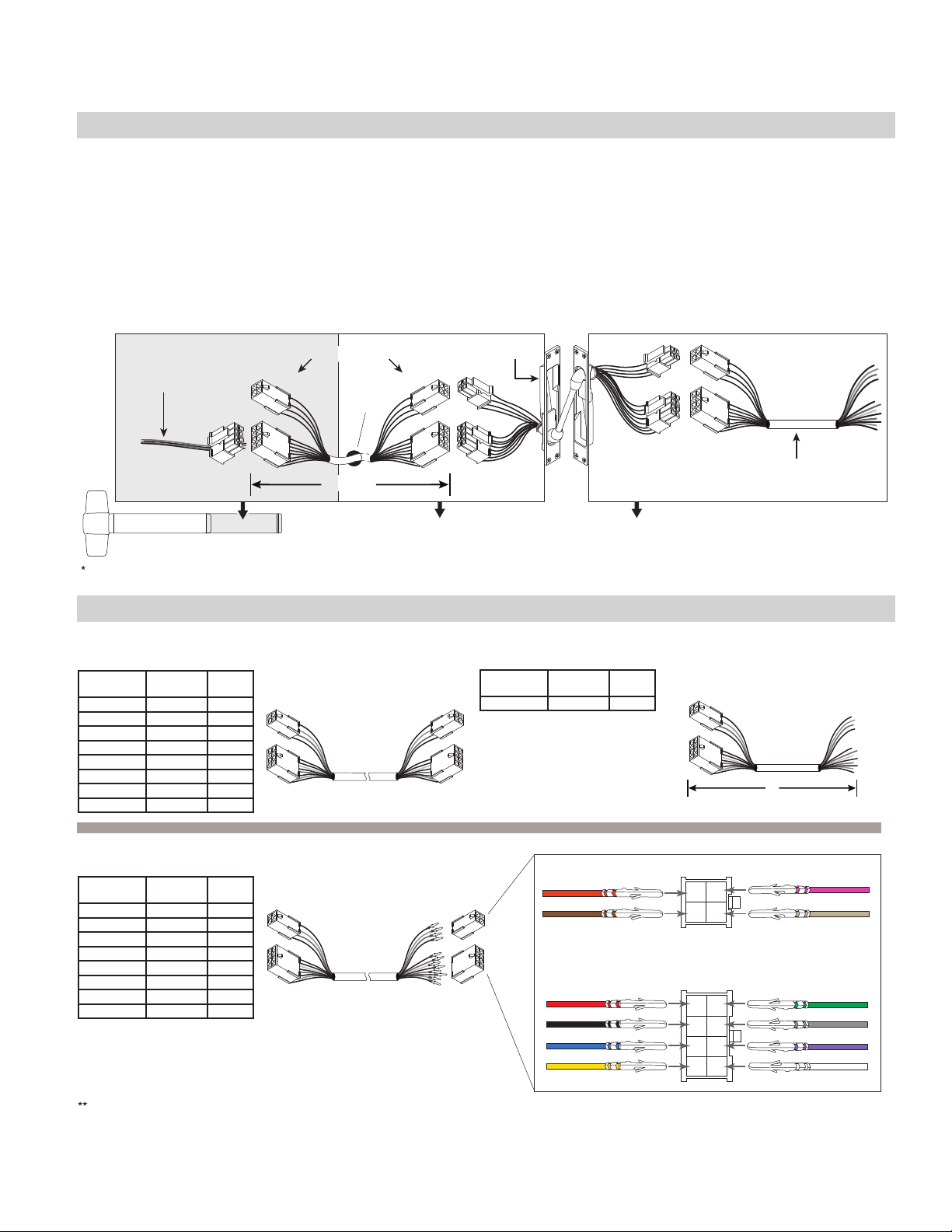
Variable Length Wiring Harnesses
The 20 gauge wiring harnesses have Allegion Connect 8 pin and 4 pin connectors on each end, or can be ordered with the connectors on one end only. One
wiring assembly is used to connect the electrified hardware to the EPT/hinge, and a 6” CON-6W wiring harness can be used to route from the EPT/hinge to
field wiring.
INTERNAL
PART #
106190
106191
106192
106193
106194
106195
106196
106197
Electrified Exit
Device, Trim,
Strike, or Lock
PART # TOTAL
CON-6
CON-12
CON-26
CON-32
CON-38
CON-44
CON-50
CON-192
Variable Length Wiring Harness
wire hole
*
in door
6" to 192"
inside device in door in frame
EPT-CON
Wiring Harnesses
Variable Length Harness
with connectors on both ends
(for use with Hollow Metal Doors)
LENGTH
6
12
26
32
38
44
50
192
INTERNAL
PART #
PART # TOTAL
LENGTH
6106210 CON-6W
CON-6W 6" Wiring Harness
(for connection to field wiring)
6" with connectors on one end only
6" Harness
(for connection to field wiring)
6”
**
**
Variable Length Harness
INTERNAL
PART #
106201
106202
106203
106204
106205
106206
106207
106208
Stripped leads of CON-6W connect to field wiring. Field wiring from frame to power supply must be appropriate gauge (Variable Length Harnesses
have 20 gauge wire and are not acceptable). Refer to wire gauge specifications in instructions for the particular electrified hardware.
PART # TOTAL
CON-6P
CON-12P
CON-26P
CON-32P
CON-38P
CON-44P
CON-50P
CON-192P
For use in tight fit applications such as routing through conduit or
through a door.
LENGTH
6
12
26
32
38
44
50
192
with connectors on one end, crimped
pins and loose connectors on other end
(for use with Wood Doors)
1 Orange
2 Brown
1 Red
2 Black
3 Blue
4 Yellow
4 Pin
123
4
Back of Connectors
8 Pin
1
5
2
6
3
7
4
8
Allegion Connect • Technical Manual • 3
3 Pink
4 Tan
5 Green
6
Gray
7
Violet
8
White
Page 4
Von Duprin Products
Electric Power Transfer: EPT-10
See page 3 for system overview and wiring harness usage.
Electrified Exit Device, Trim, Strike, or Lock
Wiring Harness
A
6" to 192"
EPT-CONVariable Length
B
CON-6W 6" Wiring Harness
(for connection to field wiring)
C
A B C
WIRE
COLOR
Orange 1
Brown 2
Pink 3
Tan 4
Red 1
Black 2
Blue 3
Yellow 4
Green 5
Gray 6
Violet 7
White 8
PIN PIN EPT
▬
►
▬
▬
▬
▬
▬
▬
▬
▬
▬
▬
▬
1 Orange
►
2 Brown
►
3
►
4
►
1 Red
►
2 Black
►
3 Blue
►
4 Yellow
►
5 Green
►
6 Gray
►
7 Violet
►
8 White
WIRE
COLORS
▬
►
▬
►
▬
►
▬
►
▬
►
▬
►
▬
►
▬
►
▬
►
▬
►
▬
►
▬
►
PIN WIRE
COLOR
1 Orange
2 Brown
3 Pink
4 Tan
1 Red
2 Black
3 Blue
4 Yellow
5 Green
6 Gray
7 Violet
8 White
NOTE: Field wiring from frame to power supply must be appropriate gauge. Refer to wire gauge specifications in instructions
for the particular hardware.
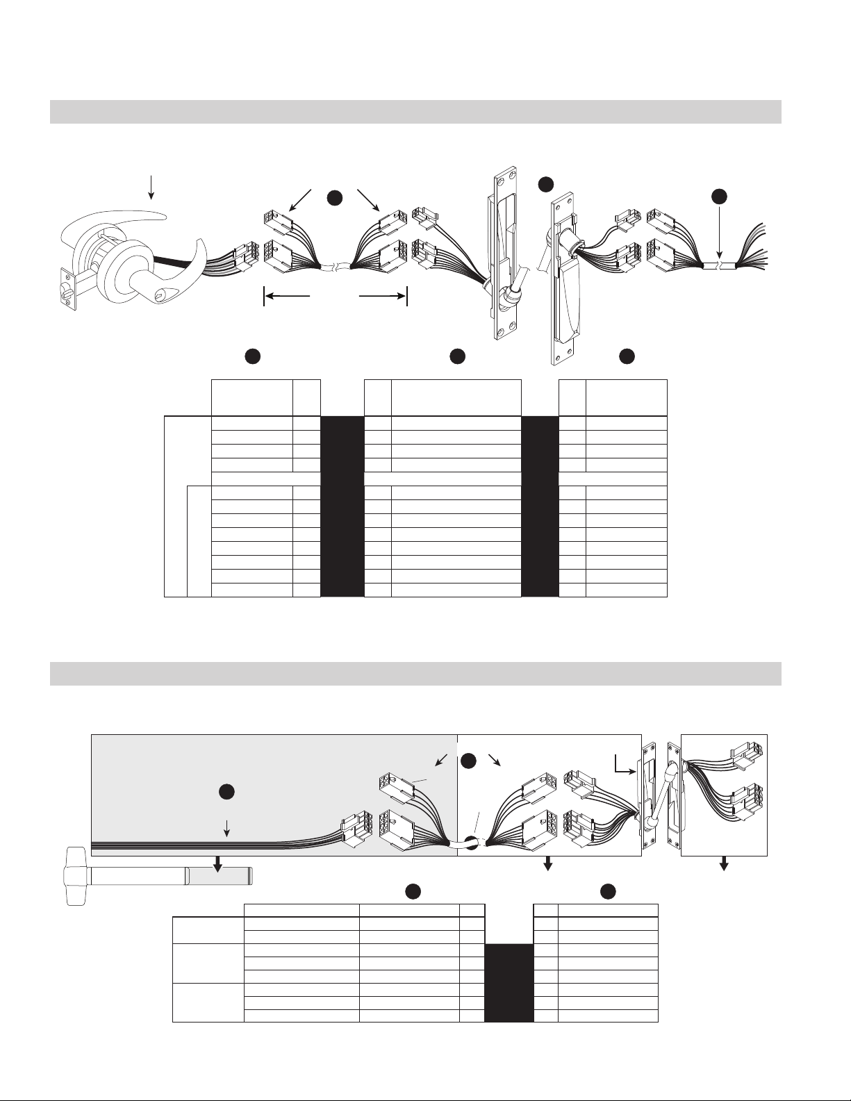
RX/LX/RX-LX Exit Device
See page 3 for system overview and wiring harness usage. Colors shown below at wiring harness should remain consistent
throughout the EPT or hinge and harness outside of frame.
EPT-CON
A
RX / LX / RX-LX CON
inside device in door in frame
Not Used
RX/
RX-LC
LX
LX-LC
4 • Allegion Connect • Technical Manual
Variable Length Wiring Harness
B
not
used
wire hole
in door
A B
FUNCTION WIRE COLOR PIN PIN WIRE COLOR
Normally Open (NO) Blue 3
Normally Closed (NC) Yellow 4
Common (C) Red or Green 5
Normally Open (NO) Gray 6
Normally Closed (NC) Violet 7
Common (C) White or Black 8
1 1 Red
2 2 Black
▬
►
▬
▬
▬
▬
▬
3 Blue
►
4 Yellow
►
5 Green
►
6 Gray
►
7 Violet
►
8 White
Page 5
Von Duprin Products
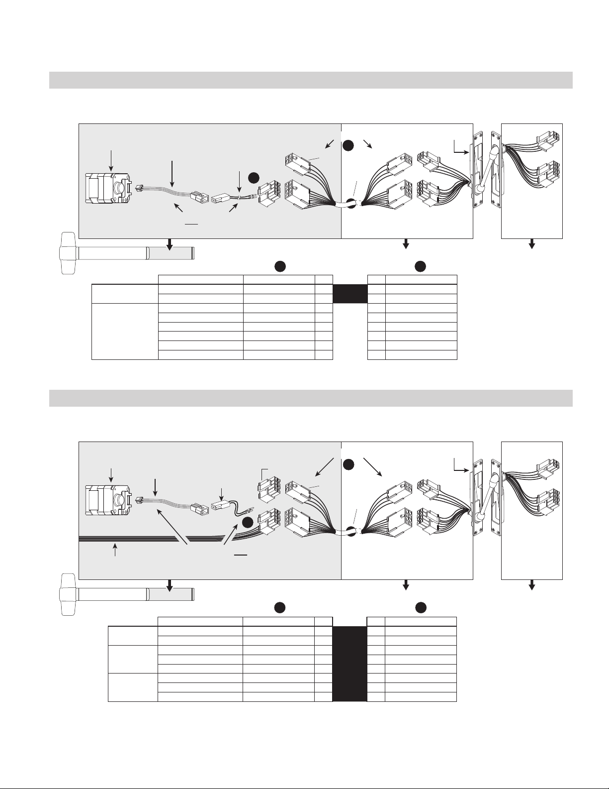
QEL Exit Device
See page 3 for system overview and wiring harness usage. Colors shown below at wiring harness should remain consistent
throughout the EPT or hinge and harness outside of frame.
QEL
Motor
QEL Motor Cable with QEL CON Adapter Harness
QEL
**
Motor Cable
114320
inside device
Adapter Harness
(see chart below)
040069
QEL CON
106198
Variable Length Wiring Harness
B
not
used
wire hole
A
in door
in door in frame
EPT-CON
BA
QEL
Not Used
FUNCTION WIRE COLOR PIN PIN WIRE COLOR
Power Black 1
Power Black 2
▬
►
►
1 Red
2 Black
▬
3 3 Blue
4 4 Yellow
5 5 Green
6 6 Gray
7 7 Violet
8 8 White
Motor and Motor Cable
*
are standard, non-CON
components.
NOTE: The 6' cable (110388) that is furnished with standard QEL devices is not furnished or required for CON applications.
QEL/(RX/LX/RX-LX) Exit Device
See page 3 for system overview and wiring harness usage. Colors shown below at wiring harness should remain consistent
throughout the EPT or hinge and harness outside of frame.
QEL
Motor
*
QEL
Motor Cable
114320
Adapter Harness
*
(see chart below)
QEL CON
106198
Variable Length Wiring Harness
not used
**
not
used
B
wire hole
in door
EPT-CON
A
QEL Motor Cable with QEL CON
RX / LX / RX-LX CON
inside device
Adapter Harness
040069
in door in frame
A B
QEL
RX/
RX-LC
LX/
LX-LC
FUNCTION WIRE COLOR PIN PIN WIRE COLOR
Power Black 1
Power Black 2
Normally Open (NO) Blue 3
Normally Closed (NC) Yellow 4
Common (C) Red or Green 5
Normally Open (NO) Gray 6
Normally Closed (NC) Violet 7
Common (C) White or Black 8
▬
▬
▬
▬
▬
▬
▬
▬
►
1 Red
►
2 Black
►
3 Blue
►
4 Yellow
►
5 Green
►
6 Gray
►
7 Violet
►
8 White
Motor and Motor Cable
*
are standard, non-CON
components.
Connector in 106198
**
not used since QEL
wires go directly to
switch connector.
NOTE: The 6' cable (110388) that is furnished with standard QEL devices is not furnished or required for CON applications.
Allegion Connect • Technical Manual • 5
Page 6

Von Duprin Products
EL Exit Device
See page 3 for system overview and wiring harness usage. Colors shown below at wiring harness should remain consistent
throughout the EPT or hinge and harness outside of frame.
EL Solenoid Variable Length Wiring Harness
*
EL Pulse
Width Module
050534
inside device in door in frame
*
EL CON
Adapter Harness
106198
(see chart below)
A
not
used
B
wire hole
in door
EPT-CON
A B
EL
Not Used
FUNCTION WIRE COLOR PIN PIN WIRE COLOR
Power Black 1
Power Black 2
▬
►
►
1 Red
2 Black
▬
3 3 Blue
4 4 Yellow
5 5 Green
6 6 Gray
7 7 Violet
8 8 White
Solenoid and Pulse
*
Width Module are
standard, non-CON
components.
NOTE: The 6' cable (110388) that is furnished with standard EL devices is not furnished or required for CON applications.
EL/(RX/LX/RX-LX) Exit Device
See page 3 for system overview and wiring harness usage. Colors shown below at wiring harness should remain consistent
throughout the EPT or hinge and harness outside of frame.
EL
Solenoid
EL Pulse
Width Module
*
050534
Adapter Harness
*
(see chart below)
EL CON
106198
not used
Variable Length Wiring Harness
B
**
not
used
wire hole
in door
EPT-CON
A
RX / LX / RX-LX CON
inside device in door in frame
A B
Solenoid and Pulse
*
Width Module are
standard, non-CON
components.
Connector in 106198
**
not used since solenoid
wires go directly to
switch connector.
EL
RX/
RX-LC
LX/
LX-LC
FUNCTION WIRE COLOR PIN PIN WIRE COLOR
Power Black 1
Power Black 2
Normally Open (NO) Blue 3
Normally Closed (NC) Yellow 4
Common (C) Red or Green 5
Normally Open (NO) Gray 6
Normally Closed (NC) Violet 7
Common (C) White or Black 8
▬
►
▬
▬
▬
▬
▬
▬
▬
1 Red
►
2 Black
►
3 Blue
►
4 Yellow
►
5 Green
►
6 Gray
►
7 Violet
►
8 White
NOTE: The 6' cable (110388) that is furnished with standard EL devices is not furnished or required for CON applications.
6 • Allegion Connect • Technical Manual
Page 7

Von Duprin Products
CX (Chexit) Motor-Driven Exit Device
See page 3 for system overview and wiring harness usage. Colors shown below at wiring harness should remain consistent
throughout the EPT or hinge and harness outside of frame.
These parts are
provided when CX
is ordered with CON.
Variable Length
Wiring Harness
ordered separately.
040191 is included with Standard CX
(no CON included).
040191 is saleable. Can be connected
to EPT-CON without using Variable
Length Wiring Harness.
CX
Module
12 Pin
Connector to
CX Module
CX CON
Adapter
Harness
116724
4+8 Pin
Connector
A
Variable Length Wiring Harness
B
wire hole
in door
OR
CX Standard 4’ Harness
B
040191
inside device in door in frame
A B
FUNCTION WIRE COLOR PIN PIN WIRE COLOR
Door Position Switch Input DPS Orange 1
Alarm Relay Output NO/NC Brown 2
Unused Wires Pink 3
Unused Wires Tan 4
Power Supply +24V Input 24VDC Red 1
Power Supply Ground GND Black 2
Alarm Relay Output COM Blue 3
Fire Alarm Input FA Yellow 4
Inhibit Input INH Green 5
Gang Input/Output GNG Gray 6
Secure Relay Output NO/NC Violet 7
Secure Relay Output COM White 8
EPT-CON
▬
►
▬
►
▬
►
▬
►
▬
►
▬
►
▬
►
▬
►
▬
►
▬
►
▬
►
▬
►
1 Orange
2 Brown
3 Pink
4 Ta n
1 Red
2 Black
3 Blue
4 Yellow
5 Green
6 Gray
7 Violet
8 White
Allegion Connect • Technical Manual • 7
Page 8
Von Duprin Products
ALK Exit Device
See page 3 for system overview and wiring harness usage. Colors shown below at wiring harness should remain consistent
throughout the EPT or hinge and harness outside of frame.
ALK
24VDC
External Inhibit
(non-polarized)
ALK CON
Adapter Harness
106182
+
inside device in door in frame
A
Variable Length Wiring Harness
B
not
used
wire hole
in door
EPT-CON
A B
ALK
Not Used
FUNCTION WIRE COLOR PIN PIN WIRE COLOR
To Power Supply +24VDC Red 1
Power Supply Ground Black 2
External Inhibit Blue 3
External Inhibit Yellow 4
▬
►
►
►
►
1 Red
2 Black
3 Blue
4 Yellow
▬
▬
▬
5 5 Green
6 6 Gray
7 7 Violet
8 8 White
E7500 Mortise Lock
See page 3 for system overview and wiring harness usage. Colors shown below at wiring harness should remain consistent
throughout the EPT or hinge and harness outside of frame.
E7500 Variable Length Wiring Harness
Adapter Harness
106198 (see chart below)
not used
*
B
not
used
A
E7500 Switch CON Adapter Harness
106181
in door in frame
A B
E7500
Solenoid
S1- monitors
auxiliary bolt and
latch bolt
S2- monitors trim
inputs (locked or
unlocked)
FUNCTION WIRE COLOR PIN PIN WIRE COLOR
Power Black 1
Power Black 2
Normally Closed (NC) Yellow 3
Normally Open (NO) Blue 4
Common (C) Red 5
Normally Closed (NC) Violet 6
Normally Open (NO) Gray 7
Common (C) White 8
▬
▬
▬
▬
▬
▬
▬
▬
►
►
►
►
►
►
►
►
1 Red
2 Black
3 Blue
4 Yellow
5 Green
6 Gray
7 Violet
8 White
EPT-CONE7500 Solenoid CON
Connector in
*
106198 not
used since
solenoid wires
go directly to
switch
connector.
8 • Allegion Connect • Technical Manual
Page 9
Von Duprin Products
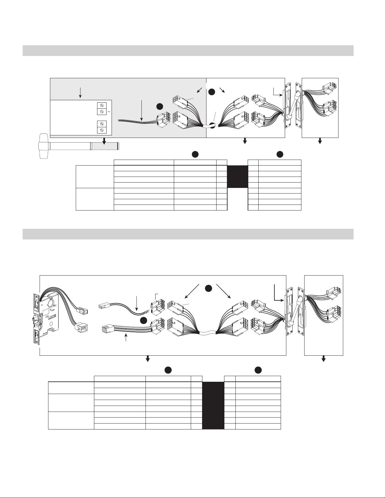
SS7500 Mortise Lock
See page 3 for system overview and wiring harness usage. Colors shown below at wiring harness should remain consistent
throughout the EPT or hinge and harness outside of frame.
SS7500 Variable Length Wiring Harness
Adapter Harness
106181
B
not
used
EPT-CONSS7500 Switch CON
A
in door in frame
A B
Not Used
S1- monitors
auxiliary bolt and
latch bolt
S2- monitors trim
inputs (locked or
unlocked)
FUNCTION WIRE COLOR PIN PIN WIRE COLOR
Normally Closed (NC) Yellow 3
Normally Open (NO) Blue 4
Common (C) Red 5
Normally Closed (NC) Violet 6
Normally Open (NO) Gray 7
Common (C) White 8
1 1 Red
2 2 Black
▬
►
▬
▬
▬
▬
▬
3 Blue
►
4 Yellow
►
5 Green
►
6 Gray
►
7 Violet
►
8 White
E996/M996 Trim
See page 3 for system overview and wiring harness usage. Colors shown below at wiring harness should remain consistent
throughout the EPT or hinge and harness outside of frame.
E996/M996 Variable Length Wiring Harness
inside device in door in frame
E996/M996 CON
Adapter Harness
106183
(see chart below)
EPT-CON
B
not
used
A
wire hole
in door
A B
E996/M996
Not Used
FUNCTION WIRE COLOR PIN PIN WIRE COLOR
Power White 1
Power Black 2
▬
►
►
1 Red
2 Black
▬
3 3 Blue
4 4 Yellow
5 5 Green
6 6 Gray
7 7 Violet
8 8 White
NOTE: The Cable.10038 that is furnished with standard E996/M996 trim is not furnished or required for CON applications.
Allegion Connect • Technical Manual • 9
Page 10

Von Duprin Products
6100/6200 Series Electric Strikes
See page 3 for system overview and wiring harness usage. Colors shown below at wiring harness should remain consistent
throughout the EPT or hinge and harness outside of frame.
Standard
Strike
6000 Strike Solenoid CON Adapter Harness
106187
(see chart below)
A
CON-6W 6" Wiring Harness
(for connection to field wiring)
not
used
B
*
A B
FUNCTION WIRE COLOR PIN PIN WIRE COLOR
Solenoid
Not Used
6” harness is for single door application. For double door application, specify variable length harness to
*
connect electric strike to power transfer.
DS
(Double Switch)
Strike
Power Black 1
Power Black 2
6000 Strike Solenoid CON
Adapter Harness
106198 (see chart below)
not used
▬
►
▬
►
▬
►
3
▬
►
4
▬
►
5
▬
►
6
▬
►
7
▬
►
8
CON-6W 6" Wiring Harness
(for connection to field wiring)
**
not
used
1 Red
2 Black
3 Blue
4 Yellow
5 Green
6 Gray
7 Violet
8 White
*
B
A
6000 Strike Switch CON Adapter Harness
106181
A B
Fail
Secure
(FSE)
Solenoid
S1- monitors
tripper
Only
S2- monitors
DS Models
strike lip
FUNCTION WIRE COLOR PIN PIN WIRE COLOR
Power Black 1
Power Black 2
Normally Closed (NC) Blue 3
Normally Open (NO) Yellow 4
Common (C) Red 5
Normally Closed (NC) Gray 6
Normally Open (NO) Violet 7
Common (C) White 8
▬
►
▬
▬
▬
▬
▬
▬
▬
1 Red
►
2 Black
►
3 Blue
►
4 Yellow
►
5 Green
►
6 Gray
►
7 Violet
►
8 White
A B
FUNCTION WIRE COLOR PIN PIN WIRE COLOR
Solenoid
Fail
Safe
(FS)
*
S1- monitors
tripper
Only
S2- monitors
DS Models
strike lip
6” harness is for single door application. For double door application, specify variable length harness to
connect electric strike to power transfer.
Power Black 1
Power Black 2
Normally Closed (NC) Blue 3
Normally Open (NO) Yellow 4
Common (C) Red 5
Normally Open (NO) Gray 6
Normally Closed (NC) Violet 7
Common (C) White 8
▬
►
▬
▬
▬
▬
▬
▬
▬
1 Red
►
2 Black
►
3 Blue
►
4 Yellow
►
5 Green
►
6 Gray
►
7 Violet
►
8 White
Connector in 106198 not used since solenoid wires go directly to switch connector.
**
10 • Allegion Connect • Technical Manual
Page 11

Falcon Products
RX Exit Device
See page 3 for system overview and wiring harness usage. Colors shown below at wiring harness should remain consistent
throughout the EPT or hinge and harness outside of frame.
RX CON
RX
Variable Length Wiring Harness
A
inside
device
FUNCTION WIRE COLOR PIN PIN WIRE COLOR
Normally Open (NO) Violet 3
Normally Closed (NC) Gray 4
Common (C) Black 5
A B
not
used
EPT-CON
B
wire hole
in door
in door in frame
1 1 Red
2 2 Black
▬
►
▬
▬
6 6 Gray
7 7 Violet
8 8 White
3 Blue
►
4 Yellow
►
5 Green
Allegion Connect • Technical Manual • 11
Page 12

Falcon Products
8
►
8 White
MEL Exit Device
See page 3 for system overview and wiring harness usage. Colors shown below at wiring harness should remain consistent
throughout the EPT or hinge and harness outside of frame.
MEL
Motor
MEL
Not Used
MEL
**
Motor Cable
114320
MEL Motor Cable with MEL CON
Adapter Harness
inside
device
FUNCTION WIRE COLOR PIN PIN WIRE COLOR
Power Black 1
Power Black 2
MEL CON
Adapter Harness
(see chart below)
040069
106198
A
Variable Length Wiring Harness
B
not
used
wire hole
in door
A B
▬
►
►
1 Red
2 Black
▬
3 3 Blue
4 4 Yellow
5 5 Green
6 6 Gray
7 7 Violet
8 8 White
in door in frame
EPT-CON
Motor and Motor Cable
*
are standard, non-CON
components.
NOTE: The 6' cable (110388) that is furnished with standard EL devices is not furnished or required for CON applications.
MEL/RX Exit Device
See page 3 for system overview and wiring harness usage. Colors shown below at wiring harness should remain consistent
throughout the EPT or hinge and harness outside of frame.
MEL
Motor
RX CON
*
Motor Cable
MEL
RX
Not
Used
MEL
114320
*
MEL CON
Adapter Harness
106198
(see chart below)
not used
A
MEL Motor Cable with MEL CON
Adapter Harness
040069
inside
device
A B
FUNCTION WIRE COLOR PIN PIN WIRE COLOR
Power Black 1
Power Black 2
Normally Open (NO) Violet 3
Normally Closed (NC) Gray 4
Common (C) Black 5
Variable Length Wiring Harness
not
used
6
7
B
wire hole
in door
▬
►
▬
►
▬
►
▬
►
▬
►
▬
►
▬
►
▬
**
in door in frame
1 Red
2 Black
3 Blue
4 Yellow
5 Green
6 Gray
7 Violet
EPT-CON
Motor and Motor Cable
*
are standard, non-CON
components.
Connector in 106198
**
not used since MEL
wires go directly to
switch connector.
NOTE: The 6' cable (47269206) that is furnished with standard MEL devices is not furnished or required for CON
applications.
12 • Allegion Connect • Technical Manual
Page 13

Falcon Products
connector.
EL Exit Device
See page 3 for system overview and wiring harness usage. Colors shown below at wiring harness should remain consistent
throughout the EPT or hinge and harness outside of frame.
EL Solenoid Variable Length Wiring Harness
*
EL Pulse
Width Module
050534
inside
device
EL 6” Adapter Cable
*
8 Pin Connector
106198
(see chart below)
with
A
not
used
B
wire hole
in door
in door in frame
EPT-CON
A B
EL
Not Used
FUNCTION WIRE COLOR PIN PIN WIRE COLOR
Power Black 1
Power Black 2
▬
►
►
1 Red
2 Black
▬
3 3 Blue
4 4 Yellow
5 5 Green
6 6 Gray
7 7 Violet
8 8 White
Solenoid and Pulse
*
Width Module are
standard, non-CON
components.
NOTE: The 6' cable (110388) that is furnished with standard EL devices is not furnished or required for CON applications.
EL/RX Exit Device
See page 3 for system overview and wiring harness usage. Colors shown below at wiring harness should remain consistent
throughout the EPT or hinge and harness outside of frame.
EL
Solenoid
EL Pulse
Width Module
*
050534
*
8 Pin Connector
(see chart below)
EL 6" Adapter
Cable with
106198
not used
Variable Length Wiring Harness
not
used
B
wire hole
in door
**
EPT-CON
A
RX CON
inside
device
in door in frame
A B
EL
RX
Not
Used
FUNCTION WIRE COLOR PIN PIN WIRE COLOR
Power Black 1
Power Black 2
Normally Open (NO) Violet 3
Normally Closed (NC) Gray 4
Common (C) Black 5
▬
►
▬
▬
▬
▬
▬
6
▬
7
▬
8
1 Red
►
2 Black
►
3 Blue
►
4 Yellow
►
5 Green
►
6 Gray
►
7 Violet
►
8 White
Solenoid and Pulse
*
Width Module are
standard, non-CON
components.
Connector in 106198
**
not used since EL wires
go directly to RX
NOTE: The 6' cable (110388) that is furnished with standard EL devices is not furnished or required for CON applications.
Allegion Connect • Technical Manual • 13
Page 14

Falcon Products
EA (Exit Alarm) Exit Device
See page 3 for system overview and wiring harness usage. Colors shown below at wiring harness should remain consistent
throughout the EPT or hinge and harness outside of frame.
EA
24VDC
External Inhibit
(non-polarized)
EA
Not Used
EAK CON Adapter Harness
+
inside
device
To Power Supply +24VDC Red 1
106182
A
FUNCTION WIRE COLOR PIN PIN WIRE COLOR
Power Supply Ground Black 2
External Inhibit Blue 3
External Inhibit Yellow 4
Variable Length Wiring Harness
not
used
A B
B
wire hole
in door
in door in frame
▬
►
▬
▬
▬
5 5 Green
6 6 Gray
7 7 Violet
8 8 White
1 Red
►
2 Black
►
3 Blue
►
4 Yellow
EPT-CON
14 • Allegion Connect • Technical Manual
Page 15

Falcon Products
Falcon Products
T-Series Electrified Locks (T851/T881)
EPT or Electrified Hinge
T851/T881 (12 VDC)
B
(6” to 192”)
Wiring Harness
Variable Length
See chart below
A
(supplied)
must be used
12 VDC Harness
12VDC
for wire colors
Power Only - T851, T881
COLOR
Harness
A B
Lock
1 Red
Connector
Connector
2 Black
->
->
PIN PIN WIRE
WIRE
3 3 Blue
COLOR
Power Red 1
Power Black 2
7 7 Violet
5 5 Green
4 4 Yellow
6 6 Gray
8 8 White
Electrical Specifications:
EL / EU
PURPOSE FUNCTION
Lock
Fail Safe/Fail Secure
.65 AMP @ 12 VDC
.32 AMP @ 24 VDC
T851 Storeroom Fail Safe:
Deadlocking latch bolt operated by lever from either side, except when outer lever is electrically locked. When outer lever is locked (inoperable), latch bolt
retracted by key in cylinder outside. Inside lever is always free.
T881 Storeroom Fail Secure:
Deadlocking latch bolt operated by lever inside at all times. Outside lever is inoperable until electrically unlocked, then latch bolt is operable from either
side. When outside lever is inoperable, latch bolt retracted by key in cylinder outside.
T-Series
12 VDC Configuration Shown
Allegion Connect • Technical Manual • 15
Not Used
Page 16

Falcon Products
EPT or Electrified Hinge
T851/T881 (24 VDC)
Variable Length
24 VDC Harness
B
(6” to 192”)
Wiring Harness
A
(supplied)
must be used
24VDC
See chart below
for wire colors
Power Only - T851, T881
COLOR
Harness
1 Red
Connector
2 Black
->
->
PIN PIN WIRE
3 3 Blue
7 7 Violet
5 5 Green
4 4 Yellow
6 6 Gray
8 8 White
A B
Lock
WIRE
Connector
COLOR
Power Red 1
Power Black 2
Lock
T-Series
24 VDC Configuration Shown
16 • Allegion Connect • Technical Manual
PURPOSE FUNCTION
EL / EU
Not Used
Page 17

Falcon Products
COLOR
Connector
1 Red
►
▬
PIN PIN WIRE
2 Black
►
▬
3 Blue
►
▬
3
4 Yellow
►
▬
4
5 Green
6 Gray
►
►
▬
▬
7 Violet
►
▬
7
8 8 White
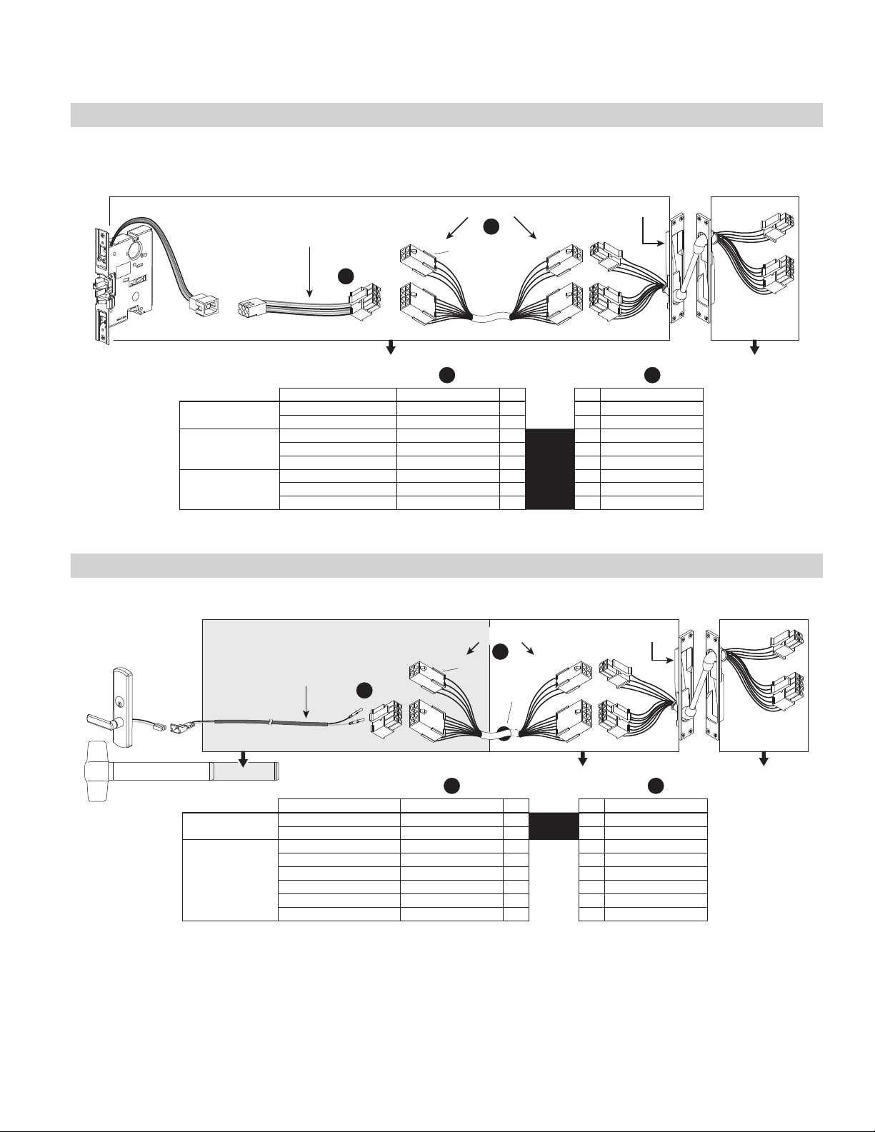
MA-Series Electrified Lock
MA851/MA881 (12 and 24 VDC)
EPT or Electrified Hinge
B
(6” to 192”)
Wiring Harness
Variable Length
A
See chart below
for wire colors
COLOR
Lock Connector Harness
MA851-RX, MA881-RX
Power Black/White 1
Power Black/White 2
EL / EU
PURPOSE FUNCTION WIRE
COLOR
Connector
1 Red
2 Black
►
►
▬
▬
PIN PIN WIRE
A A BB
COLOR
Lock Connector Harness
Common Orange 5
RX
Not Used
Not Used
3 3 Blue
4 4 Yellow
5 5 Green
RX Switch NO Green 6
Not Used
6 6 Gray
7 7 Violet
Not Used
8 8 White
Electrical Specifications:
Power Only - MA851, MA881
MA-Series Lock
Fail Safe/Fail Secure
.65 AMP @ 12 VDC
.32 AMP @ 24 VDC
MA851 Storeroom Fail Safe/Electrified EL:
Latch bolt operated by knob/lever from either side except when outer knob/lever is electrically locked. When outer knob/lever is locked, latch bolt
retracted by key in cylinder outside. Deadlocking latch. Inside knob/lever always free for immediate egress. Specify 12 or 24 VDC.
MA881 Storeroom Fail Secure/Electrified EU:
Latch bolt operated by knob/lever from inside except when outer knob/lever is electrically unlocked, then latch bolt from either side. When locked, key in
cylinder outside retracts latch bolt. Deadlocking latch. Inside knob/lever always free for immediate egress. Specify 12 or 24 VDC.
12 VDC Configuration (2 Black Power Wires)
24 VDC Configuration (2 White Power Wires)
Allegion Connect • Technical Manual • 17
Power Black/White 1
Power Black/White 2
EL / EU
PURPOSE FUNCTION WIRE
Not Used
Page 18

Schlage Products
Schlage Products
Harness
Connector
PIN PIN WIRE
Lock
Connector
COLOR
1 Red
►
▬
COLOR
Power Black 1
2 Black
►
▬
Power Black 2
3 Blue
►
▬
Normally Open (NO) Blue 3
4 Yellow
►
▬
Normally Closed (NC) Yellow 4
5 Green
6 Gray
►
►
▬
▬
Common (C) Green 5
Normally Open (NO) Gray 6
7 Violet
►
▬
Normally Closed (NC) Violet 7
8 White
►
▬
Common (C) White 8
EPT or Electrified Hinge
L Series Locks (8-pin connector)
Variable Length
B
(6” to 192”)
Wiring Harness
A
Power + RX + LX - 909XEL/EU RX LX, L949XEL/EU RX LX
Power + RX - 909XEL/EU RX, L949XEL/EU RX
See charts below
for wire colors
BA A AB B
8-Pin8-Pin8-Pin8-Pin
PURPOSE FUNCTION WIRE
Harness
Connector
PIN PIN WIRE
Lock
Connector
PURPOSE FUNCTION WIRE
Harness
Connector
PIN PIN WIRE
EL / EU
COLOR
1 Red
►
▬
COLOR
Power Black 1
EL / EU
COLOR
1 Red
►
▬
2 Black
►
▬
Power Black 2
2 Black
►
▬
3 Blue
►
▬
Normally Open (NO) Blue 3
3 3 Blue
RX
4 Yellow
►
▬
Normally Closed (NC) Yellow 4
RX
4 4 Yellow
5 Green
►
▬
6 6 Gray
Common (C) Green 5
5 5 Green
6 6 Gray
LX
7 7 Violet
8 8 White
Not Used
7 7 Violet
8 8 White
L Lock
Power Only - 909XEL/EU, L949XEL/EU
18 • Allegion Connect • Technical Manual
Lock
Connector
PURPOSE FUNCTION WIRE
COLOR
Power Black 1
EL / EU
Power Black 2
Not Used
Page 19

Schlage Products
Harness
Connector
PIN PIN WIRE
Lock
Connector
COLOR
1 Red
►
▬
COLOR
Power Black 1
2 Black
►
▬
Power Black 2
3 Blue
►
▬
Normally Open (NO) Blue 3
4 Yellow
►
▬
Normally Closed (NC) Yellow 4
5 Green
6 Gray
►
►
▬
▬
Common (C) Green 5
Normally Open (NO) Gray 6
7 Violet
►
▬
Normally Closed (NC) Violet 7
8 White
►
▬
Common (C) White 8
L Series Locks (8-pin + 4-pin connector)
EPT or Electrified Hinge
(6” to 192”)
Wiring Harness
Variable Length
A
or
RX/LX/DPS
RX/LX/DBM
B
Power + RX + LX - 909XEL/EU RX LX, L949XEL/EU RX LX
Power + RX - 909XEL/EU RX, L949XEL/EU RX
See charts below
for wire colors
BA A AB B
8-Pin8-Pin8-Pin8-Pin
PURPOSE FUNCTION WIRE
Harness
Connector
PIN PIN WIRE
Lock
Connector
PURPOSE FUNCTION WIRE
Harness
Connector
PIN PIN WIRE
Lock
Connector
EL / EU
COLOR
1 Red
►
▬
COLOR
Power Black 1
EL / EU
COLOR
1 Red
►
▬
COLOR
2 Black
►
▬
Power Black 2
2 Black
►
▬
3 Blue
►
▬
Normally Open (NO) Blue 3
3 3 Blue
RX
4 Yellow
►
▬
Normally Closed (NC) Yellow 4
RX
4 4 Yellow
5 Green
►
▬
6 6 Gray
Common (C) Green 5
5 5 Green
6 6 Gray
LX
7 7 Violet
8 8 White
Not Used
7 7 Violet
8 8 White
COLOR
Harness
Connector
1 Orange
2 Brown
3 Pink
1 OrangeNormally Open (NO)
2 BrownNormally Closed (NC)
3 PinkCommon (C)
►
►
►
►
►
▬
▬
▬
2
3
1
PIN PIN WIRE
Lock
A B
Connector
+ DBM (deadbolt monitor) or DPS (door position switch)
4-Pin
PURPOSE FUNCTION WIRE
Pink
Brown
Orange
COLOR
Common (C)
Normally Open (NO)
Normally Closed (NC)
DBM
▬
▬
4 4 Tan
1
Red 2
Green/Black
not used
DPS
►
▬
3
White/Black
not used 4 4 Tan
Power Black 1
Power Black 2
Power Only - 909XEL/EU, L949XEL/EU
PURPOSE FUNCTION WIRE
EL / EU
Not Used
Allegion Connect • Technical Manual • 19
Page 20

Schlage Products
EPT or Electrified Hinge
Harness
Connector
PIN PIN WIRE
Lock
Connector
COLOR
1 1 Red
COLOR
2 2 Black
3 Blue
►
▬
Violet
4 Yellow
►
▬
Gray
5 Green
►
▬
White
6 6 Gray
7 7 Violet
8 8 White
ND Series Locks
B
(6” to 192”)
Wiring Harness
Variable Length
RX Only - 10 RX, 12 RX, 80 RX, 96 RX
PURPOSE FUNCTION WIRE
COLOR
Harness
Connector
1 Red
►
▬
PIN PIN WIRE
Lock
Connector
COLOR
Power Black 1
Power + RX - 12EL/EU RX, 80EL/EU RX, 96EL/EU RX
PURPOSE FUNCTION WIRE
Normally Open (NO) 3
Not Used
2 Black
3 Blue
►
►
▬
▬
▬
Power Red 2
Normally Open (NO) Violet 3
RX
EL / EU
Normally Closed (NC) 4
RX
4 Yellow
►
Normally Closed (NC) Gray 4
Common (C) 5
5 Green
►
▬
6 6 Gray
Common (C) White 5
Not Used
7 7 Violet
8 8 White
Not Used
See charts below
A
ND Lock
for wire colors
A B A B A B
Power Only - 12EL/EU, 80EL/EU, 96EL/EU
20 • Allegion Connect • Technical Manual
Harness
Connector
PIN PIN WIRE
Lock
Connector
PURPOSE FUNCTION WIRE
COLOR
1 Red
►
▬
COLOR
Power Black 1
EL / EU
2 Black
►
▬
Power Red 2
3 3 Blue
4 4 Yellow
5 5 Green
6 6 Gray
7 7 Violet
Not Used
8 8 White
Page 21

Ives Products
Ives Products
C
COLOR
CON-6W 6" Wiring Harness
(for connection to field wiring)
B
Electrified Hinge with 4+8 Pin Connectors
(TW4 and TW8 do not include 4 pin connector)
1 Orange
2 Brown
3 Pink
►
►
►
▬
▬
▬
PIN PIN WIRE
TW12
COLORS
HINGE WIRE
COLORS
TW8 MON
HINGE WIRE
TW8
COLORS
HINGE WIRE
1 Red
2 Black
4 Ta n
►
▬
3 Blue
4 Yellow
►
►
►
►
▬
▬
▬
▬
▬
5 Green
►
7 Violet
6 Gray
8 White
►
►
►
▬
▬
▬
A
6" to 192"
COLORS
TW4 MON
HINGE WIRE
Variable Length Wiring HarnessElectrified Exit Device, Trim, Strike, or Lock
3CB1/5BB1 TW/TWM Architectural Hinge
A B B B B B C
The TW4 MON, TW8 MON, and TW12 Electrified Hinges are supplied with Allegion Connect 8 pin and 4 pin connectors. The TW4 and TW8 Electrified Hinges are
supplied with Allegion Connect 8 pin connectors.
COLORS
HINGE WIRE
1 Green Green Orange 1
2 Black Black Brown 2
3 White White Pink 3
►
►
►
▬
▬
▬
PIN PIN TW4
WIRE
COLOR
Pink 3
Brown 2
Orange 1
1 Red Red Red Red Red 1
2 Yellow Yellow Yellow Yellow Yellow 2
4 Tan 4
►
▬
Tan 4
3 Violet Violet Violet Violet Violet 3
4 Gray Gray Gray Gray Gray 4
►
►
►
►
▬
▬
▬
▬
Red 1
Blue 3
Black 2
Yellow 4
7 White / Violet White / Violet White / Violet 7
5 White / Red White / Red White / Red 5
6 White / Yellow White / Yellow White / Yellow 6
8 White / Gray White / Gray White / Gray 8
►
►
►
►
▬
▬
▬
▬
Gray 6
Violet 7
Green 5
White 8
NOTE: Field wiring from frame to power supply must be appropriate gauge. Refer to wire gauge specifications in instructions for the particular hardware.
Allegion Connect • Technical Manual • 21
Page 22

Ives Products
A B B C
CON-6W 6" Wiring Harness
(for connection to field wiring)
COLOR
B C
700CS-TWP with 4+8 Pin Connectors
(700-TW8 does not include 4 pin connector)
1 Orange
2 Brown
3 Pink
►
►
►
▬
▬
▬
PIN PIN WIRE
WIRE
COLORS
700CS-TWP
WIRE
COLORS
1 Red
2 Black
4 Ta n
►
▬
3 Blue
►
►
►
►
▬
▬
▬
▬
7 Violet
5 Green
4 Yellow
6 Gray
8 White
►
►
►
►
▬
▬
▬
▬
A
6" to 192"
Variable Length Wiring HarnessElectrified Exit Device, Trim, Strike, or Lock
700-TW8/700CS-TWP Continuous Hinge
1 Orange 1
2 Brown 2
3 Red with Yellow Stripe 3
►
►
►
▬
▬
▬
PIN PIN 700-TW8
1 Red Red 1
2 Black Black 2
4 Black with Yellow Stripe 4
►
▬
3 Blue Blue 3
►
►
►
►
▬
▬
▬
▬
7 Violet Violet 7
5 Green Green 5
4 Yellow Yellow 4
6 Orange Gray 6
8 White White 8
►
►
►
►
▬
▬
▬
▬
The 700-TW8 is supplied with Allegion Connect 8 pin connectors. The 700CS-TWP is supplied with Allegion Connect 8 pin and 4 pin connectors.
22 • Allegion Connect • Technical Manual
Tan 4
WIRE
COLOR
Pink 3
Brown 2
Orange 1
Red 1
Blue 3
Black 2
Gray 6
Violet 7
White 8
Green 5
Yellow 4
700-TW8
700CS-TWP
NOTE: Field wiring from frame to power supply must be appropriate gauge. Refer to wire gauge specifications in instructions for the particular hardware.
Page 23

Ives Products
A B C
CON-6W 6" Wiring Harness
(for connection to field wiring)
C
COLOR
XY-TWP with 4+8 Pin ConnectorsVariable Length Wiring HarnessElectrified Exit Device, Trim, Strike, or Lock
112XY/224XY-TWP Continuous Hinge
1 Red
2 Black
3 Blue
►
►
►
▬
▬
▬
PIN PIN WIRE
WIRE COLORS
1 Orange 1
2 Brown 2
3 Red with Yellow Stripe 3
A B
6" to 192"
►
►
►
▬
▬
▬
PIN PIN X Y-TWP
Red 1
Blue 3
Black 2
WIRE
COLOR
1 Red
2 Black
4 Yellow
►
▬
4 Black with Yellow Stripe 4
►
▬
Yellow 4
3 Blue
►
►
►
▬
▬
▬
▬
1 Red 1
2 Black 2
3 Blue 3
►
►
►
▬
▬
▬
▬
Red 1
Blue 3
Black 2
7 Violet
5 Green
4 Yellow
6 Gray
8 White
►
►
►
►
►
▬
▬
▬
▬
7 Violet 7
5 Green 5
4 Yellow 4
6 Gray 6
8 White 8
►
►
►
►
►
▬
▬
▬
▬
Gray 6
Violet 7
White 8
Green 5
Yellow 4
NOTE: Field wiring from frame to power supply must be appropriate gauge. Refer to wire gauge specifications in instructions for the particular hardware.
Allegion Connect • Technical Manual • 23
Page 24

Ives Products
A B B C
CON-6W 6" Wiring Harness
C
(for connection to field wiring)
COLOR
1 Orange
2 Brown
3 Pink
►
►
►
▬
▬
B
PIN PIN WIRE
Electrified Pivot with 8 Pin ConnectorsVariable Length Wiring HarnessElectrified Exit Device, Trim, Strike, or Lock
TW8
PIVOT WIRE
PIVOT WIRE
A
6" to 192"
Intermediate and Pocket Pivots
PIN PIN TW4
▬
COLORS
COLORS
1 1
2 2
3 3
►
►
►
▬
▬
▬
1 Red
2 Black
4 Ta n
►
▬
4 4
►
▬
3 Blue
►
►
►
►
▬
▬
▬
▬
1 Red Red 1
2 Yellow Yellow 2
3 Violet Violet 3
►
►
►
►
▬
▬
▬
▬
7 Violet
5 Green
4 Yellow
6 Gray
8 White
►
►
►
►
▬
▬
▬
▬
7 - White / Violet 7
5 - White / Red 5
4 Gray Gray 4
6 - White / Yellow 6
8 - White / Gray 8
►
►
►
►
▬
▬
▬
▬
The TW4 and TW8 Electrified Pivots are supplied with Allegion Connect 8 pin connectors.
24 • Allegion Connect • Technical Manual
Tan 4
WIRE
COLOR
Pink 3
Brown 2
Orange 1
Red 1
Blue 3
Black 2
Gray 6
Violet 7
White 8
Green 5
Yellow 4
NOTE: Field wiring from frame to power supply must be appropriate gauge. Refer to wire gauge specifications in instructions for the particular hardware.
NOTE: Applies for 7215/7226/7227 PT INT, 7215F/7226F/7227F PT INT, 7230F/7237F PT INT, E91105F.
Page 25

Connector Kit
Connector Kit
Included in Kit (CON-KIT 050823):
4-pin Male Connectors 8-pin Male Connectors 4-pin Female Connectors 8-pin Female Connectors
(Qty. 10) (Qty. 10) (Qty. 10) (Qty. 10)
Female Terminals (Qty. 100)
compatible with 20-24 gauge wires
Can be purchased elsewhere (Molex part number 63819-0000)
See next page for instructions
Not Included in Kit:
Crimping Tool
This will be required to install terminals on loose wires
Extraction Tool
Male Terminals (Qty. 100)
compatible with 20-24 gauge wires
1 Orange
2 Brown
4 Pin Female
Back of
Connector
123
4
8 Pin Female
Wire Color to Pin Alignment
3 Pink
4 Tan
3 Pink
4 Tan
4 Pin Male
Back of
Connector
3
1
24
8 Pin Male
1 Orange
2 Brown
1 Red
2 Black
3 Blue
4 Yellow
Back of
Connector
1
5
2
6
3
7
4
8
5 Green
6 Gray
7 Violet
8 White
5 Green
6 Gray
7 Violet
8 White
Back of
Connector
1
5
2
6
3
7
4
8
Allegion Connect • Technical Manual • 25
1 Red
2 Black
3 Blue
4 Yellow
Page 26

Connector Kit
Extraction Tool Instructions
1 Insert extractor tool tip into front of connector on either side of the terminal until it stops.
Connector
Extraction
Tool
2 Rotate tool clockwise then counter-clockwise approximately 25º to 30º in each direction, once or twice.
3 Repeat steps 1 and 2 on the opposite side of terminal until tabs are bent down.
Tabs Up
Tabs Down
4 Pull wire out of back of connector housing.
NOTE: Removal damages the terminal locking tangs. The terminal is not reusable.
Connector
Extraction
Tool
26 • Allegion Connect • Technical Manual
Page 27

About Allegion
Allegion (NYSE: ALLE) creates peace of mind by pioneering safety and security.
As a $2 billion provider of security solutions for homes and businesses, Allegion
employs more than 8,000 people and sells products in more than 120 countries
across the world. Allegion comprises 27 global brands, including strategic
brands CISA®, Interflex®, LCN®, Schlage® and Von Duprin®.
For more, visit www.allegion.com.
© 2020 Allegion
110380, Rev. 10/20-5.0.5
Customer Service
1-877-671-7011 www.allegion.com/us
 Loading...