

Page 1
*911066-00*
911066-00
Concealed Vertical Rod Exit Device
for Metal Doors
5547EO, 5547DT,
5547L, 5547NL,
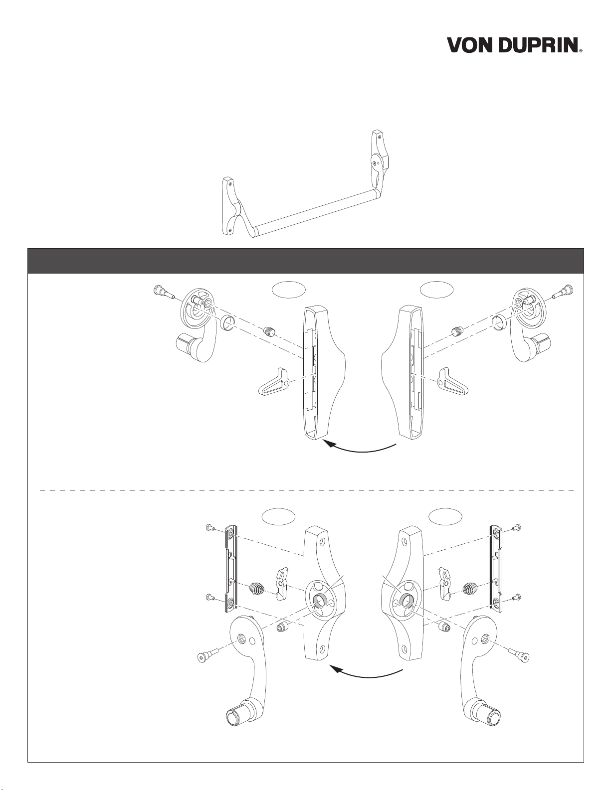
1 Check handing of device. Reverse if necessary.
Installation Instructions
& 5547TL
b b
REVERSING PROCEDURE
FOR LOCK STILE CASE
Invert the case and
reassemble in order shown
(a thru d) with opposite hand
lever arm from hinge case.
REVERSING PROCEDURE
FOR HINGE STILE CASE
Disassemble hinge stile case,
rotate parts as shown with spring
always at the bottom. Reassemble
in order shown (a thru d) with
opposite hand lever arm from
center case.
LH lever
arm
LHR
RHR
a a
Lock Stile Case
LHR
Bushing
RHR
aa
RH lever
arm
dd
cc
RH lever
arm
When exchanging parts, be certain that one bushing remains on the hub of each case.
Hinge Stile Case
bb
LH lever
arm
Page 2
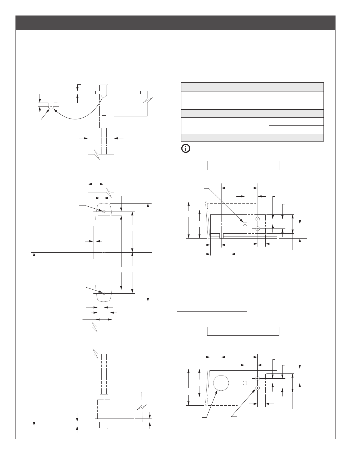
2 Prepare door.
This device is for metal door only.
a. Tape door template (page 4) to inside face of lock stile according to handing. Be sure vertical centerline of device on template
is parallel to edge of door and backset is as shown in schedule below. Be sure horizontal centerline of device is 39-13/16” from
nished oor.
b. Prepare door as shown.
c. Prepare door for top and bottom bolt guides. See Figures 1 and 2 below.
d. If door requires trim, make additional preparations per trim template.
¹⁄₄"
⁷⁄₃₂" R
"A" or "B" - See
page 4 template
for correct hole
See
backset
schedule
preparation
³⁄₁₆" Min. to
edge of stop
¹⁄₄"
⁷⁄₃₂"
1³⁄₄" Min. stile
width
X
Device & Latch Bolt
C
L
¹⁄₄"
3"
7¹⁄₄"
C
L
Device
DEVICE INSTALLATION SCHEDULE
Installation
Flush hollow metal door
Minimum 1-3/4" to 2-1/2" door stile
Stiles wider than 2-1/2"
Stop height of 1/2" minimum required.
FIG. 1 (TOP PREP)
Device & Latch Bolt
C
L
#12-24 Tap
3 holes
2¹⁄₄"
1³⁄₄"
⁵⁄₈"
1¹⁄₄" Typ.
2⁷⁄₃₂"
³⁄₄"
Backset
from high side
of bevel
2-1/2"
Single Door 1-9/32"
Double Door 1-5/32"
1/2 of stile
¹⁹⁄₆₄"
¹⁹⁄₃₂"
¹⁄₂"
1¹⁄₈"
⁷⁄₈"
C
L
Latch
Bolt
2
"A" or "B" - See
page 4 template
for correct hole
preparation
39¹³⁄₁₆"
to finished
floor
¹⁄₄" max undercut
¹⁵⁄₃₂"
1³⁄₁₆"
or threshold
needed
5¹⁄₂"
¹⁵⁄₁₆"
of trim if required
C
L
X
3"
⁷⁄₃₂"
METAL DOOR
APPLICATION
Inside face of lock stile
LHR shown, RHR opposite
FIG. 2 (BOTTOM PREP)
Device & Latch Bolt
C
L
⁵⁄₈"
1³⁄₄"
2¹⁄₄"
¹⁵⁄₁₆" Dia.
2⁷⁄₃₂"
#12-24 Tap
3 holes
³⁄₄"
¹⁄₂"
¹⁹⁄₆₄"
¹⁹⁄₃₂"
⁷⁄₈"
1¹⁄₈"
C
L
Latch
Bolt
Page 3

THIS PAGE
INTENTIONALLY
BLANK
3
Page 4

DEVICE INSTALLATION SCHEDULE
Installation
Flush hollow metal door
Minimum 1-3/4" to 2-1/2" door stile
Stiles wider than 2-1/2"
Backset
from high side
of bevel
2-1/2"
Single Door 1-9/32"
Double Door 1-5/32"
1/2 of stile
DEVICE
BACKSET
(SEE SCHEDULE)
C
L
BACKSET
(SEE SCHEDULE)
Actual Size
1"
Do Not Scale
Stop height of 1/2" minimum required.
SCREW CHART
Check door material and metal thickness
For correct hole preparation
A B
Aluminum Doors
Unreinforced Hollow Metal Doors
7/32" Dia.
2 holes for sex bolt head
DEVICE
C
L
Reinforced
Hollow Metal Doors
1/4-28 Tap
2 holes for hex stud
XX
RHRLHR
EDGE OF
STOP
(Single door
application
only)
3/16" MIN.MIN. 3/16"
TO FINISHED
4
39¹³⁄₁₆"
FLOOR
EDGE OF
STOP
(Single door
application
only)
IF REQUIRED
OF TRIM
LHR DOOR
C
L
XX
OF TRIM
IF REQUIRED
C
L
RHR DOOR
Page 5

THIS PAGE
INTENTIONALLY
BLANK
5
Page 6

3 Install rod control assembly.
Blind fastener package
Conrm orientation before installing. “Top” and “Bottom” of each assembly is marked with a label. Spring is at the bottom.
A B
ALUMINUM DOOR
UNREINFORCED
HOLLOW METAL DOOR
a. Check metal thickness of door. If 1/8" or less, using blind fastener package,
place a washer under the sex bolt. If metal thickness is greater than 1/8",
omit the washer.
b. Remove burrs and insert sex bolt head into 7/32" diameter hole from interior
of door thru rod control cutout.
c. Thread sex bolt anchor on sex bolt head and tighten.
d. Remove sex bolt anchor and install rod control assembly with spring towards
bottom of door.
e. Replace sex bolt anchors.
Sex bolt
anchor (2)
Use washer for
1/8" or less
thickness only
REINFORCED
HOLLOW METAL DOOR
a. Check for reinforcing. If not reinforced, follow procedure
for aluminum doors. If reinforced, continue with steps b,
c, and d below.
b. Tap 1/4-28 thread for hex stud.
c. Install rod control assembly with spring towards bottom
of door.
d. Using blind fastener package, install hex studs.
Hex stud (2)
#12 S.A.E. washer (2)
Sex bolt head (2)
Sex bolt
anchor (2)
Hex stud (2)
Sex bolt
head (2)
#12 S.A.E.
washer (2)
6
Page 7

4 Assemble top rod according to door height.
Maximum approved door height for a 5547 non-re device is 10’.
• All stock size devices are furnished with adjustable top rods to t door heights from 6’8” to 8’.
• Extension rods are available for door heights up to 10’ (non-re devices only).
e. Assemble top rod tube over hex rod. Align hole in tube that corresponds to predrilled height.
f. Assemble rod member on thumbturn or lever devices if required (376L and 376T only). See directions in control box.
g. Install rod connector pins. Do not peen yet.
Rod connector
Top rod furnished with
(4) predrilled holes to
provide additional
adjustment if required.
6'8" 6'10" 7'0" 7'2" Door
pins
TOP ROD
Rod member used with
376L and 376T trim only
8'0" Door hole
on end
Hex rod Rod connector pin
Miscellaneous Door Heights up to 8'0"
a. Measure door opening height (finished floor to rabbet)
b. Subtract measured height from 8'0" to get difference
c. Measure this difference from the 8'0" hole on the hex rod and mark a line.
d. Assemble top rod tube over hex rod. Align hole in tube with the scribed line.
e. Mark location of the hole in the tube on the hex rod.
f. Drill a 3/16" hole thru the hex rod.
g. Align the holes and install the rod connector pins. Do not peen yet.
7'2" Hole Drill 3/16" Hole 8'0" Hole
Difference
Miscellaneous Door Heights up to 10'0"
a. Measure door opening height (finished floor to rabbet)
b. Subtract measured height from 10'0" to get difference
c. Measure this difference from the 10'0" hole on the hex rod and mark a line.
d. Assemble top rod tube over hex rod. Align hole in tube with the scribed line. Cut hex rod if required.
e. Mark location of the hole in the tube on the hex rod.
f. Drill a 3/16" hole thru the hex rod.
g. Align the holes and install the rod connector pins. Do not peen yet.
Top rod tube
Constant Dimension
Door Opening Height
Difference
For non-fire devices, extension rods are
available for door heights up to 10'.
Constant Dimension
Door Opening Height
Difference
8'0"
-
=
10'0"
-
=
Drill 3/16" Hole 10'0" Hole
Difference
7
Page 8

5 Install cylinder release bracket to top rod assembly (if required).
For 5547NL devices only (supplied with trim).
Note that handing stamped on bracket corresponds
with handing of door.
a. Install cylinder release bracket.
b. Secure with top socket retaining screw.
Cylinder release
bracket
Tabs
Top rod
connector
c
a
Top socket
retaining screw
b
d
6 Set latch projection.
a. Prior to installing top rod assembly into door channel, conrm 1/2” latch projection and alignment to rod control assembly as
shown below. Adjust as needed.
b. Peen the rod connector pins securely.
Align to hole for
socket retaining screw
Top rod furnished with (4) predrilled holes to
provide additional adjustment if required.
1/2" latch
projection
a
Rod control
assembly
Rod connector pins
b
Top
of door
7 Install top rod and bolt guide assembly.
a. Slip top rod assembly thru opening in top of door.
b. Insert top rod connector into rod control assembly. Start socket retaining screw (from blind fastener package) into rod control .
c. Cut top bolt guide as hand of door requires.
d. Install top bolt guide assembly.
Top
of door
b
Rod control
assembly
a
Cut off here for RHR door
Top bolt guide
assembly
c
Cut off here for LHR door
d
8
LHR shown
Page 9

8 Assemble bottom rod.
Bottom rod furnished with four pre-drilled holes
a. Assemble bottom rod. Select correct hole for desired length.
b. Peen the rod connector pin securely.
BOTTOM ROD
Rod connector pin
b
a
to provide additional adjustment if required
9 Install bottom rod and bolt guide assembly.
a. Slip bottom rod assembly thru opening in bottom of door.
b. Insert rod connector into rod control assembly. Start socket retaining screw (from blind fastener package) into rod control.
c. Install bottom bolt guide assembly (cut rst if required).
d. Adjust bottom rod connector until bolt has 1/2” extension, then tighten socket set screw. n
Bottom
of door
a
b
Rod control
assembly
For 1-3/4" narrow
c
stile application,
cut at dotted line.
Bottom
bolt guide
assembly
d
¹⁄₂"
1/4" maximum undercut or threshold needed
9
Page 10

10 Adjust top rod.
a. Depress top latch bolt. It should stay retracted. If latch does
not stay retracted, adjust top rod at rod control assembly.
Depress plunger to verify latch release.
Top of
door
b. If using NL trim, adjust cylinder release bracket to contact
trim cylinder cam, if required. Secure with top socket
retaining screw.
c. Test top and bottom bolt extension and retraction by lifting
rod control with screwdriver or equivalent tool. Full latch
bolt extension is 1/2”.
Top of
door
Adjust rod member as needed (376L and 376T trim only).
11 Apply outside trim (if required).
a. See directions in trim carton. Line “X-X” on trim template
corresponds to line “X-X” on device template and is parallel
to edge of door. Locate line “X-X” on outside face of door.
b. Prepare outside face of lock stile and apply trim.I
12 Attach lock stile case to door.
Use short screws from device mounting package 900520.
13 Hang door and install sill strike or threshold, if any.
C
of Bolt
L
1⁷⁄₈"
¹⁄₄"
304L Strike
FLAT SILL
APPLICATION
C
of Bolt
L
10
³⁄₄" Dia.
LATCH TRACK
THRESHOLD APPLICATION
Page 11

14 Install sot strike.
a. For wood frame, locate sot strike position and mortise
frame for strike.
• 472-U strike for 1-3/4” thick door
• 473-U strike for 2-1/4” thick door
C
Latch bolt
L
¹⁄₂"
b. For non-reinforced metal frame, locate sot strike position
and prepare for 471-U strike. Double door application
shown. For single door application use appropriate handing
as shown
Suggested
mortar guard
6" Min.
1" Min.
472-U strike for 1³⁄₄" doors
473-U strike for 2¹⁄₄" doors
1¹⁄₁₆"
2¹⁄₈"
#10 wood screws for
wood frames, 4 holes.
Size of pilot holes
for wood frames depends
on hardness of wood
²⁵⁄₃₂"
1⁹⁄₁₆"
WOOD FRAME PREPARATION
1"
1¹⁄₂"
¹⁵⁄₁₆" ¹⁄₁₆"
⁷⁄₁₆"
³⁄₈"
³⁄₄"
Edge of
stop
⁷⁄₈"
¹⁄₂"
¹⁄₈"
C
L
Latch bolt
¹⁄₁₆" to ³⁄₃₂"
Door opening -
C
L
double door application
Latch bolt
C
L
LHR door
1⁵⁄₁₆"
²¹⁄₃₂"
¹⁵⁄₁₆"
⁷⁄₈"
1³⁄₄"
Double door application
shown. For single door
application, use appropriate
handing as shown.
¹⁷⁄₃₂"
1¹⁄₁₆"
⁹⁄₃₂"
³⁄₁₆" Dia.
C'sink ⁵⁄₁₆" Dia.
x 82° in frame
2 holes each strike
Latch bolt
C
L
RHR door
471-U STRIKE
HOLLOW METAL FRAME PREPARATION
Edge of stop
Strike
C
L
⁹⁄₃₂"
c. For aluminum and reinforced hollow metal frame
preparation, see below.
1⁵⁄₁₆" Min.
⁷⁄₁₆"
⁷⁄₈"
³⁄₄"
Edge of stop
Latch
C
L
bolt
REINFORCED HOLLOW METAL
AND ALUMINUM FRAME PREPARATION
11
Page 12

15 Apply hinge stile case and crossbar tube.
case parallel to
a. Remove lever arm wedge-tite set screws. Make sure
wedges and split rings are installed on lever arms.
a. Dog lever arms in depressed position.
b. Slip crossbar tube on lock stile and hinge stile lever arms.
(See instruction 941009 for cutting crossbar, if necessary.)
c. Be sure crossbar is level and hinge stile case is parallel to
edge of door and approximately on centerline of exposed
stile.
Exposed stile
C
L
Mark door
for location
of sex bolts
Device
C
L
Hinge stile
edge of door
39¹³⁄₁₆"
to finished
floor
d. Using holes in hinge stile case, mark location and prepare
door for sex bolts. Drill 13/32” dia. outside and 3/8” dia.
inside.
e. Seat sexbolts in hinge stile of door with a soft hammer to
prevent marking of door and sexbolts.
f. With crossbar in place, install hinge stile case using 625
sexbolts and C\v” mounting screws from mounting package
900520.
g. Tighten wedge-tite set screws securely with dog key and
screwdriver or equivalent for leverage, and test crossbar for
free action. (See instruction 941009.)
Customer Service
1-877-671-7011 www.allegion.com/us
© Allegion 2019
Printed in U.S.A.
911066-00 Rev. 03/19-c
 Loading...