


Piston Diaphragm
Dosing Pump
KM 254
Operation Manual
15.720039-V1.0
Please read the Operating and Servicing Manual completely and retain for future reference!

KM 254 en
Imprint
Piston Diaphragm Dosing Pump KM 254
Operation Manual
Version 1.0
Issued by
ALLDOS Eichler GmbH
Reetzstraße 85 • 76327 Pfinztal (Söllingen)
Postfach 1160 • 76317 Pfinztal
Germany
Tel. ++49 (0) 72 40 61-0 / Fax. ++49 (0) 72 40 61-177
Mail: alldos.de@alldos.com
Internet: www.alldos.com
© 2005 by ALLDOS Eichler GmbH
Subject to change.
2 15.720039-V1.0

KM 254 en
Content
Imprint............................................................................................. 2
1 General ........................................................................................... 6
1.1 Introduction ......................................................................................6
1.2 Information About the Product .........................................................6
1.2.1 Pump Types ..................................................................................6
1.2.2 Pump Performance ........................................................................6
1.2.3 Accuracy ........................................................................................7
1.2.4 Admission Pressure and Counterpressure / Suction Height .........7
1.2.5 Sound Pressure Level ...................................................................8
1.2.6 Degree of Protection .....................................................................8
1.2.7 Mains Voltage ................................................................................8
1.2.8 Ambient and Operating Conditions ................................................8
1.2.9 Dosing Medium ..............................................................................9
1.3 Application of the Device .................................................................9
1.3.1 Appropriate, Acceptable and Correct Usage .................................9
1.4 Warranty ........................................................................................10
2 Safety ........................................................................................... 11
2.1 Identification of Safety Instructions in the Operation Manual ........11
2.2 Qualification and Training of Personnel .........................................11
2.3 Risks When Safety Instructions Are Not Observed .......................11
2.4 Safety-Conscious Working ............................................................11
2.5 Safety Instructions for the Operator / User ....................................12
2.6 Safety Instructions for Maintenance, Inspection and Installation
Work ..............................................................................................12
2.7 Unauthorised Modification and Manufacture of Spare Parts .........12
2.8 Improper Operating Methods .........................................................12
2.9 Safety of the System in the Event of a Failure in the Dosing
System ...........................................................................................13
3 Transport and Intermediate Storage ............................................. 14
3.1 Transport .......................................................................................14
3.1.1 Delivery .......................................................................................14
3.1.2 Return ..........................................................................................14
3.2 Unpacking ......................................................................................14
3.3 Intermediate Storage .....................................................................14
4 Product Description and Accessories ........................................... 15
4.1 General Description .......................................................................15
4.1.1 Combined overpressure and degassing valve ............................16
4.1.2 Diaphragm protection system AMS .............................................16
4.1.3 Double diaphragm system / Diaphragm breakage signal
(optional) .....................................................................................16
4.2 Dimensional Drawing ....................................................................17
4.3 Weight ...........................................................................................18
4.4 Stroke volume ................................................................................18
V1.0 III

KM 254 en
4.5 Versions ......................................................................................... 18
4.5.1 Dosing heads: Materials and Additional Features ....................... 18
4.5.2 Valves: Materials and Additional Features ..................................18
4.6 Materials ........................................................................................19
4.7 Data of contact manometer for MBS (optional) .............................19
4.8 Installation Location .......................................................................19
4.8.1 Space Required for Operation and Maintenance ........................19
4.8.2 Permissible Ambient Influences ..................................................19
4.8.3 Underground ...............................................................................20
5 Installation .................................................................................... 21
5.1 Mounting ........................................................................................21
5.2 General Information on Installation ................................................21
5.2.1 Approximate values when using pulsation dampers ...................21
5.2.2 Installation Examples and Tips ....................................................22
5.3 Tube/Pipe Lines .............................................................................25
5.3.1 General ........................................................................................25
5.3.2 Connecting the Suction and Pressure Lines ...............................25
5.3.3 Connecting a liquid-heated dosing head (optional) .....................25
6 Electrical Connections .................................................................. 27
6.1 Electrical servomotor (optional) .....................................................27
6.2 Electronic stroke preset counter (optional) ....................................27
6.3 Electrically heated dosing head (optional) .....................................27
6.4 Diaphragm control (optional) .........................................................27
6.5 Connecting the Power Supply Cable .............................................28
7 Start-up/Shutdown ........................................................................ 29
7.1 Safety Information .........................................................................29
7.2 Initial Start-Up/Subsequent Start-Up .............................................29
7.2.1 Checks Before Start-Up ...............................................................29
7.2.2 Oil filling .......................................................................................29
7.2.3 Filling the dosing head for the initial start-up for systems
without dosing medium flooded suction .......................................29
7.2.4 Start-Up/Subsequent Start-Up .....................................................30
7.2.5 After start-up ................................................................................30
7.3 Setting the pressure relief valve ....................................................31
7.4 Zero Point Adjustments .................................................................31
7.4.1 Adjusting the zero point for system pressures up to 100 bar ......31
7.4.2 Adjusting the Zero Point ..............................................................32
7.5 Operating the pump .......................................................................32
7.6 Shutdown ....................................................................................... 33
7.6.1 Switching Off/Uninstalling ............................................................33
7.6.2 Cleaning ......................................................................................33
7.6.3 Storage ........................................................................................33
7.6.4 Disposal .......................................................................................33
IV 15.720039-V1.0

KM 254 en
8 Operating the Pump ..................................................................... 34
8.1 Switching On/Off ............................................................................34
8.1.1 Switching On the Pump ...............................................................34
8.1.2 Switching Off the Pump ...............................................................34
8.2 Setting the dosing capacity ............................................................34
8.2.1 Setting the dosing flow and locking the stroke adjustment
button ..........................................................................................34
8.3 Electrical servomotor (optional) .....................................................34
8.4 Electronic stroke preset counter (optional) ....................................34
8.5 Electrically heated dosing head (optional) .....................................34
9 Maintenance ................................................................................. 36
9.1 General Notes ...............................................................................36
9.2 Diaphragm breakage control for diaphragm breakage signal ........36
9.3 Intervals for cleaning and maintenance .........................................36
9.4 Checking the oil level .....................................................................37
9.5 Cleaning the suction and pressure valves .....................................37
9.6 Changing the diaphragm and gear oil for dosing head with single
diaphragm (no MBS) .....................................................................39
9.6.1 Drain gear oil ...............................................................................39
9.6.2 Removing the dosing head ..........................................................39
9.6.3 Replacing a single diaphragm (no MBS) ..................................... 39
9.6.4 Fitting the dosing head ................................................................40
9.6.5 Filling gear oil ..............................................................................40
9.6.6 Checking the oil level. ..................................................................40
9.7 Replacing the diaphragm for dosing head with double diaphragm 41
9.7.1 Removing the dosing head ..........................................................41
9.7.2 Replace the double diaphragm. ...................................................41
9.7.3 Fitting the dosing head ................................................................42
9.7.4 Filling the double diaphragm with separating agent ....................42
9.7.5 Filling gear oil ..............................................................................43
9.7.6 Checking the oil level. ..................................................................43
9.7.7 Cleaning the ball check valve ......................................................43
10 Possible Errors ............................................................................. 45
11 Spare Parts ................................................................................... 47
12 Dosing Curves .............................................................................. 49
EC Declaration of Conformity (Translation).................................. 52
V1.0 V
1 General
1.1 Introduction
This operation manual contains all the information required for starting up and handling
the described KM 254 pump.
If you require further information or if any problems arise, which are not discussed in
detail in this operation manual, contact ALLDOS directly for the information needed.
ALLDOS Eichler GmbH
Reetzstr. 85
D-76327 Pfinztal (Söllingen), Germany
The ALLDOS service centre can be reached via our fax service or hotline:
Fax: ++49 (0) 61-211 - Reference "Quality Service"
Hotline: ++49 (0) 61-230
1.2 Information About the Product
1.2.1 Pump Types
The KM 254 piston diaphragm dosing pump is available for a variety of power ranges in
various sizes:
Pump types and designation see type plate
The following is indicated on the type plate of the pump:
• The pump type
specifies the stroke volume, connection size, performance data (see below).
• The serial number of the pump
which is used to store and access the pump configuration at ALLDOS.
• The most important characteristics of the pump configuration
e.g. for dosing head and valve materials, they are described in the "Product Descrip-
tion and Accessories" section.
• Maximum flow rate, maximum counterpressure
• Mains frequency
KM 254 en
The following is indicated on the type plate of the pump drive:
• required energy
• mains frequency
• power consumption
• degree of protection
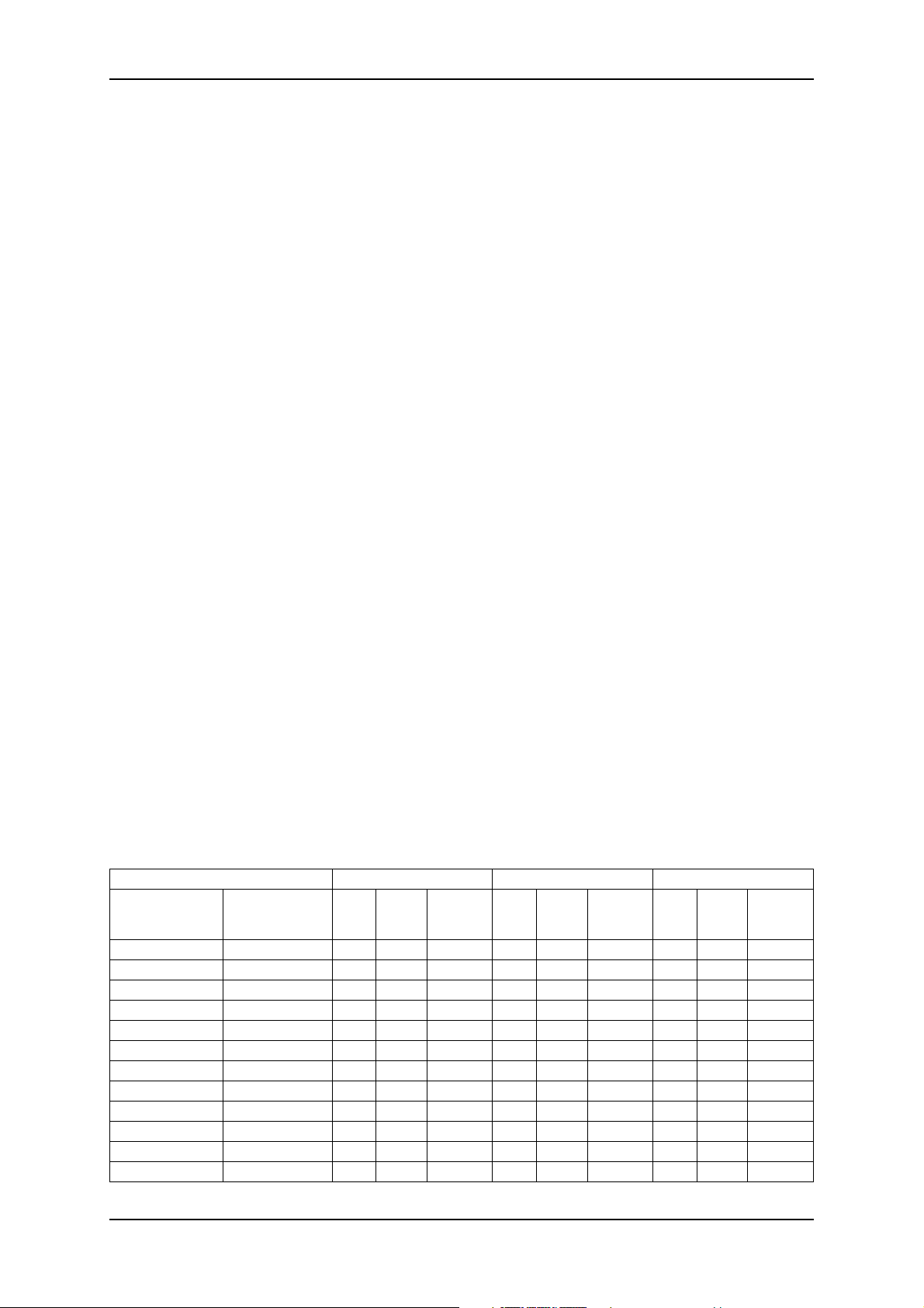
1.2.2 Pump Performance
Performance data at maximum pump counterpressure
Type 50 Hz 60 Hz 100 Hz
Q*
p max
[l/h]
Singlepump Doublepump
254-50 254-50/2 50 10 26 60 10 31 101 10 52
254-102 254-102/2 102 10 54 122 10 65 203 10 108
254-143 254-143/2 143 10 75 172 10 90 286 10 150
254-175 254-175/2 175 10 92 210 10 110 — — —
254-213 254-213/2 213 10 112 255 10 134 — — —
254-291 254-291/2 291 10 153 — — — — — —
254-46 254-46/2 46 16 26 55 16 31 92 16 52
254-97 254-97/2 97 16 54 116 16 65 193 16 108
254-136 254-136/2 136 16 75 163 16 90 271 16 150
254-166 254-166/2 166 16 92 200 16 110 — — —
254-202 254-202/2 202 16 112 242 16 134 — — —
254-276 254-276/2 276 16 153 — — — — — —
[bar]
stroke
value
[n/min]
Q*
[l/h]
p max
[bar]
stroke
value
[n/min]
Q*
[l/h]
p max
[bar]
stroke
value
[n/min]
6 15.720039-V1.0

KM 254 en General
* l/hr per dosing head; double the capacity for double pumps.
Note
The pump can be operated in the range between 10% and 100% of the maximum
dosing capacity.
1.2.3 Accuracy
Note
Dosing flow
smaller ± 1 %
fluctuation
Linearity
deviation
±1 % of the full-scale value (for water with a fully deaerated
dosing head)
1.2.4 Admission Pressure and Counterpressure / Suction Height
Maximum admission pressure at the suction side [bar]
Typ e [bar]
KM 254 5
Minimum counterpressure at the pressure valve of the pump [bar]
Typ e [bar]
KM 254 2
A positive pressure difference of 2 bar min. is required between the suction valve
and the pressure valve in order for the dosing pump to operate correctly. If the total
counterpressure (at the dosing point) and geodetic height difference between the
suction valve and the dosing point is less than 2 bar (20 m WS), a pressure
retention valve must be installed directly in front of the dosing point.
Maximum counterpressure* [bar]
Typ e
Singlepump Doublepump
254-50 254-50/2
254-102 254-102/2
254-143 254-143/2
254-175 254-175/2
254-213 254-213/2
254-291 254-291/2
254-46 254-46/2
254-97 254-97/2
254-136 254-136/2
254-166 254-166/2
254-202 254-202/2
254-276 254-276/2
*Observe the maximum permissible temperatures
p max
[bar]
10
16
V1.0 7
Maximum suction height * [m] for media with a viscosity similar to water
Typ e
Singlepump Doublepump
254-50 254-50/2
254-102 254-102/2
254-143 254-143/2
254-175 254-175/2
254-213 254-213/2
254-291 254-291/2 flooded suction
254-46 254-46/2
254-97 254-97/2
254-136 254-136/2
254-166 254-166/2
254-202 254-202/2
254-276 254-276/2 flooded suction
*applies to a filled dosing head
Maximum suction height [m] for media with maximum permissible viscosity
Typ e [m]
KM 254 flooded suction
Suction height
max. [m WS]
1
1
KM 254 en
1.2.5 Sound Pressure Level
Type
KM 254 65 ± 5 dB (A), testing according to DIN 45635-01-KL3
1.2.6 Degree of Protection
Depending on the motor variant that is selected, see type plate of the motor.
The specified degree of protection can only be ensured, if the mains cable is connected
with the same degree of protection.
1.2.7 Mains Voltage
Power supply for AC voltage
Nominal voltage Deviation from the nominal value
230 / 400 V ± 10 %
240 / 415 V ± 10 %
115 V ± 10 %
max. permissible mains impedance
(0.084 + j 0.084) Ohm (testing according to DIN EN 61000-3-11)
these details refer to 50 Hz
1.2.8 Ambient and Operating Conditions
Permissible ambient
temperature
Permissible
storage temperature
Permissible humidity relative humidity: 70% at 40 °C, 90% at 35 °C
0 °C to + 40 °C (for an installation height up to 1000 m over NN)
- 20 °C to + 70 °C
Caution
Risk of malfunction or damage to the device!
The installation site must be under cover!
Pumps with electronics are only suitable for indoor use!
Do not install outdoors!
8 15.720039-V1.0

KM 254 en General
1.2.9 Dosing Medium
Note
In the event of questions regarding the material resistance and suitability of the KM
254 for specific dosing media, please contact the manufacturer.
The dosing medium must fulfil the following characteristics for standard version
pumps:
•Liquid
• Non-abrasive *
• non-combustible **
* The dosing of abrasive media is possible with certain versions, on request,
** the dosing of combustible media is possible with certain versions of explosion protected pumps, in
according with ATEX.
Maximum permissible viscosity at operating temperature*
up to stroke
Typ e
KM 254 300 100 5
* The specified values are approximate values and refer to
the standard version of pumps.
Dosing Medium:
Newtonian liquid
non-degassing
without suspended matter
density similar to water
Please note the increasing viscosity at lower temperatures!
value 63 [n / min]
Viscosity (max.) * mPas
stroke value 64 - 120
[n / min]
from stroke
value 121 [n /
min]
Caution
Caution
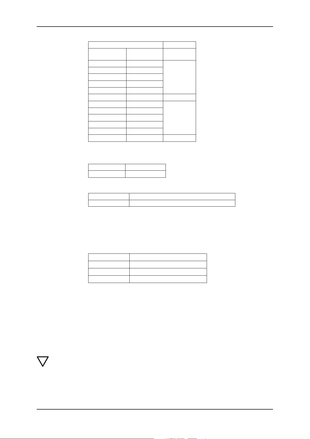
Permissible media temperature
Dosing head
material
PVC 0 °C 40 °C 20 °C
1.4571 * -10 °C 100 °C 100 °C
2.4610 * -10 °C 100 °C 100 °C
PP 0 °C 40 °C 20 °C
PVDF -10 °C
* At 70°C maximum counterpressure of 3 ba
* For SIP/CIP applications, 145 °C is permissible for a short period of time (approx. 15 min) at < 2
bar.
Min. media
temperature
Max. media temperature < 10 bar
60 °C
70° C at 9 bar
Max. media temperature < 16 bar
20 °C
Risk of malfunction or damage to the device!
The dosing medium must be in liquid phase!
Observe the freezing and boiling point of the dosing medium!
Risk of malfunction or damage to the device!
The resistance of the parts that come into contact with the media depends on the
media, media temperature and operating pressure. Ensure the parts that come into
contact with the media are chemically resistant to the dosing medium in operating
conditions!
Observe the manufacturer's safety instructions when handling chemicals!
Observe limitations of dosing media depending on type of pump!
1.3 Application of the Device
1.3.1 Appropriate, Acceptable and Correct Usage
The KM 254 pump, described here is suitable for dosing liquid media strictly in accordance with the instructions in this manual.
V1.0 9
Note
!
Warning
!
Warning
1.4 Warranty
KM 254 en
Pumps in explosion protected version are identified accordingly on the pump type
plate and motor type plate, and an EC Declaration of conformity is provided in
accordance with guidelines 94/9/EC, which replaces the EC Declaration of conformity which is printed in this instruction manual.
To operate a pump which has been identified as an explosion protected pump for
the dosing of combustible liquids or for operation in potentially explosive operating sites in accordance with guideline 94/9/EC, refer to the enclosed instruction
manual “Operating an explosion protected pump” in addition to this operation
manual.
Other applications or the operation of pumps in ambient and operating conditions,
which are not approved, are considered improper and are not permitted. ALLDOS
Eichler GmbH accepts no liability for any damage resulting from incorrect use.
Warranty in accordance with our general terms of sales and delivery shall only be valid if:
• The KM 254 pump is used in accordance with the information within this operation
manual
• The KM 254 pump is not opened or incorrectly handled
• Repairs are only carried out by authorised and qualified personnel
• Only original spare parts are used for repairs
10 15.720039-V1.0

KM 254 en Safety
2 Safety
This operation manual contains general instructions that must be observed during installation, operation and maintenance of the pump. This operation manual must therefore be
read by the installation engineer and the relevant qualified personnel/operators prior to
installation and start-up, and must be available at the installation location of the pump at
all times.
It is not only the general safety instructions described in this "Safety" section that must be
observed, but all special safety instructions that are provided in the other sections.
2.1 Identification of Safety Instructions in the Operation Manual
Safety instructions or other advice included in this operation manual, which, if not followed
could result in personal injury or damage to the pump and its functions, are identified with
the following symbols:
!
Warning
Risk of accidents and injury!
Warning
Risk accidents and injury caused by electrical voltage!
Caution
Risk of malfunction or damage to the device!
Note
There is an exceptional feature.
Information provided directly on the pump, e.g.
• Labelling of fluid connections
• Arrow indicating the direction of rotation
must be observed and must be legible at all times.
2.2 Qualification and Training of Personnel
Operating, maintenance, inspection and installation personnel must have the relevant
qualifications. The responsibility and supervision of personnel must be strictly controlled
by the operator. Personnel must be trained and instructed if they do not have the required
level of knowledge. If necessary, this can be done by the manufacturer/supplier at the
request of the operator of the pump. It is the responsibility of the operator to make sure
that the contents of the operation manual are understood by the personnel.
2.3 Risks When Safety Instructions Are Not Observed
If safety instructions are not observed, this may have dangerous consequences for
humans, the environment and the pump. If safety instructions are not observed, this may
lead to the loss of any claims for damages.
If individual safety instructions are not observed, this may cause the following damage, for
example:
• Failure of important functions of the pump/system
• Failure of specified methods for maintenance
• Harm to humans from exposure to electrical, mechanical and chemical influences
• Damage to the environment from leakage of harmful substances
2.4 Safety-Conscious Working
The safety instructions described in this operation manual, applicable national regulations
for accident prevention and any internal working, operating and safety regulations of the
operator must be observed.
V1.0 11
KM 254 en
2.5 Safety Instructions for the Operator / User
Hazardous hot or cold parts on the pump must be protected to prevent accidental contact.
Leakages of dangerous substances (e.g. hot, toxic) must be disposed of in a way that is
not harmful to humans or the environment. Legal regulations must be observed.
Damage caused by electrical energy must be prevented (for more details see, e.g. the
regulations of the VDE and the local power supply company).
2.6 Safety Instructions for Maintenance, Inspection and Installation Work
The operator is responsible for ensuring that all maintenance, inspection and installation
work is carried out by authorised and qualified personnel, who have been adequately trained by reading the operation manual.
All work on the pump should only be carried out when it is stopped. The procedure described in the operation manual for stopping the pump must be observed.
Pumps or pump units which produce media that are harmful to health must be decontaminated.
All safety and protective equipment must be immediately restarted or put into operation
once work is complete.
Observe the points described in the initial start-up section prior to subsequent start-up.
Warning
Electrical connections should only be connected by qualified personnel!
The pump housing must only be opened by personnel authorised by ALLDOS!
Observe the manufacturer's safety instructions when handling chemicals.
When working on the dosing head, connections or lines:
Wear the necessary protective clothing (goggles, gloves)!
Before removing the dosing head, valves and media lines, empty any remaining
medium in the dosing head into a driptray by carefully unscrewing the suction
valve.
!
Warning
Install pump so that it is easily accessible for operation and maintenance purposes.
Observe the resistance of the parts that come into contact with the media depends
on the media, media temperature and operating pressure! Observe the restrictions
of the dosing media depending on the pump type.
Only use the specified line types!
Do not open pump, electronics and sensors!
Repairs must only be carried out by authorised and qualified personnel!
Observe flow direction (arrow) of valves!
Do not operate pump next to closed slides. Risk of damage!
2.7 Unauthorised Modification and Manufacture of Spare Parts
Modification or changes to the pump are only permitted following agreement with the
manufacturer. Original spare parts and accessories authorised by the manufacturer are
safe to use. Using other parts can result in liability for any resulting consequences.
2.8 Improper Operating Methods
The operational safety of the supplied pump is only ensured if it is used in accordance
with the "General" section of the operation manual. The specified limit values should on
no account be exceeded.
Note
Pumps in explosion protected version are identified accordingly on the pump type
plate and motor type plate, and an EC Declaration of conformity is provided in
accordance with guidelines 94/9/EC, which replaces the EC Declaration of
conformity which is printed in this instruction manual.
12 15.720039-V1.0
KM 254 en Safety
!
Warning
To operate a pump which has been identified as an explosion protected pump for
the dosing of combustible liquids or for operation in potentially explosive operating sites in accordance with guideline 94/9/EC, refer to the enclosed instruction
manual “Operating an explosion protected pump” in addition to this operation
manual.
If the assumption is made that a safe operation is no longer possible, switch off the
pump and protect it against unintentional operation.
This action should be taken
• if the pump has been damaged,
• if the pump no longer seems to be operational,
• if the pump has been stored for an extended period of time in poor conditions.
2.9 Safety of the System in the Event of a Failure in the Dosing System
KM 254 dosing pumps are designed according to the latest discoveries and are carefully
manufactured and tested. However, a failure may occur in the dosing system. Systems in
which dosing pumps are installed must be designed in such a way that the safety of the
entire system is still ensured following a failure of the dosing pump. The relevant monitoring and control functions are designed for this.
V1.0 13

3 Transport and Intermediate Storage
3.1 Transport
Caution
Risk of malfunction or damage to the pump! Do not throw or drop the pump.
3.1.1 Delivery
The piston diaphragm dosing pump KM 254 is supplied in different packaging depending
on the overall delivery. For transport and intermediate storage, use the correct packaging
to protect the pump against damage.
3.1.2 Return
Clean the pump thoroughly
• before it is returned or stored. It is essential that there are no traces of toxic or
hazardous media remaining on the pump,
• Drain oil from the drive mechanism,
• package pump correctly.
Caution
Risk of malfunction or damage to the pump! ALLDOS accepts no liability for
damage caused by incorrect transportation, missing or unsuitable packaging of the
pump, residual media or leaking oil!
KM 254 en
3.2 Unpacking
Retain the packaging for future storage or return, or dispose of the packaging in accordance with local regulations.
3.3 Intermediate Storage
storage temperature
Permissible
Permissible
humidity
-20°C to +70°C
max. 70 % rel. at 40 °C
max. 90 % rel. at 35 °C
14 15.720039-V1.0

KM 254 en Product Description and Accessories
4 Product Description and Accessories
4.1 General Description
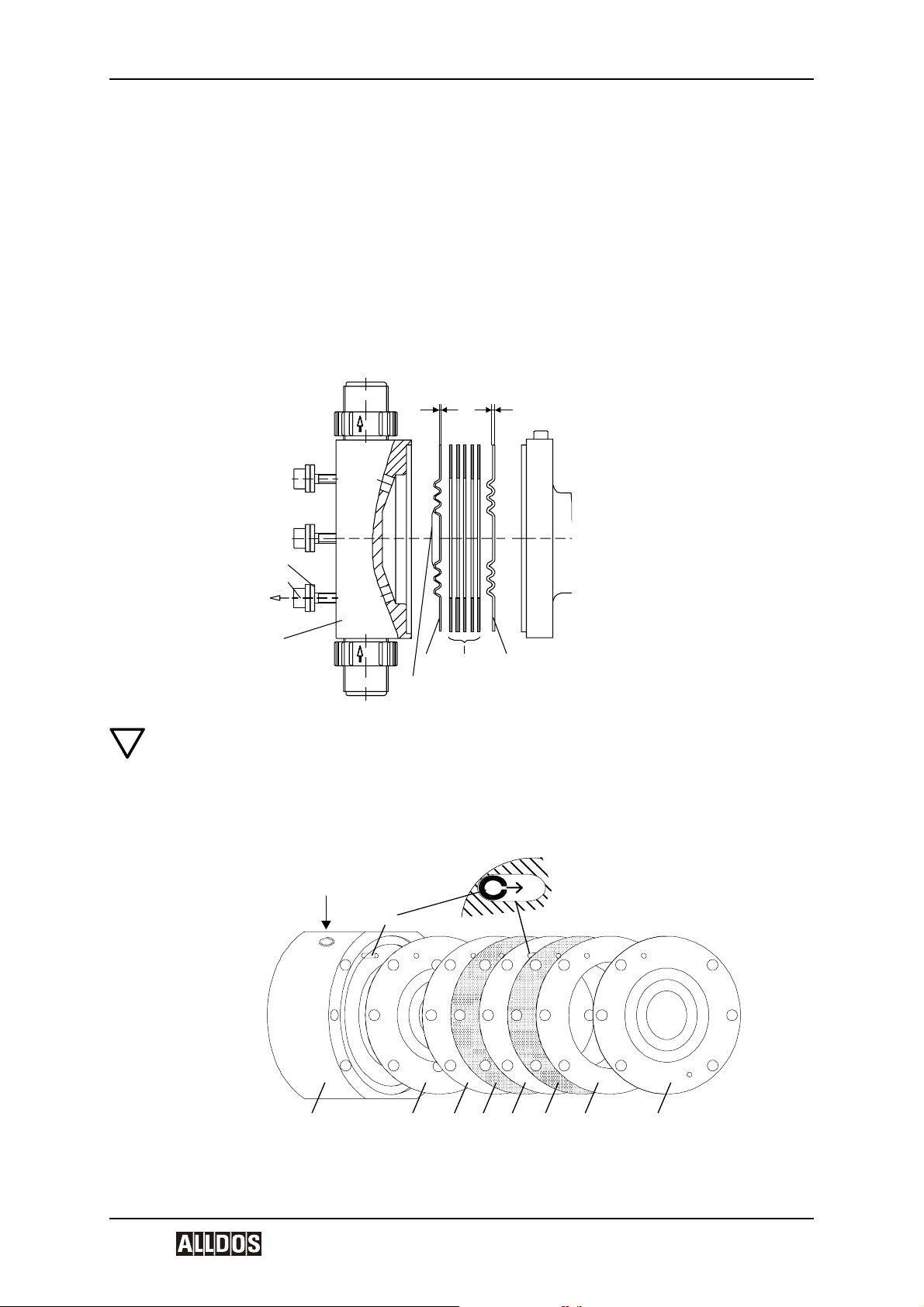
The KM 254 are oscillatory positive-displacement pumps with hydraulic diaphragm control. The operation procedure of the dosing pump is shown in the sectional drawing.
The rotational movement of the drive motor (1p) is converted via the worm gearing (2p)
and eccentric (3p) into the oscillatory suction and stroke movement of the piston (6p). The
piston has a hollow bore and a row of radial control holes, which provide a hydraulic connection between the drive area and the piston stroke area. The sliding plug (5p) envelops
the holes during the stroke and seals the stroke area from the drive area.
The hydraulic excursion of the solid teflon diaphragm (Q) displaces an equivalent volume
of dosing medium from the dosing head (2) into the dosing line. With the suction stroke,
the piston creates a low pressure, which propagates in the dosing head, the ball valve
(3b) on the dosing side closes and the dosing medium flows through the suction valve
(3a) into the dosing head.
The stroke volume size is solely determined by the position of the sliding plug. The active
stroke length and corresponding average dosing flow can therefore be changed continuously and linearly from 10-100 % using the stroke adjustment button and Nonius (L).
M3b
3a 9p 3p2p5p6p2Q 4p
1p
F
L
χ
ε
V1.0 15

1p Motor
2p Worm gearing
3p Eccentric
4p Recuperating spring (not with drive size 3)
5p Sliding plug
6p Piston
M combined overpressure and degassing valve
9p Diaphragm protection valve (AMS)
Q Dosing diaphragm
2 Dosing head
3a Suction valve
3b Pressure valve
L Stroke adjustment button
F Aeration screw with oil-level gauge
4.1.1 Combined overpressure and degassing valve
The combined overpressure and degassing valve (M) opens if there is an excessively
high build-up of pressure in the dosing system and provokes the constant degassing of
the hydraulic medium.
4.1.2 Diaphragm protection system AMS
The diaphragm protection system AMS (9p) has a keypad, which is connected to the
dosing diaphragm. The dosing diaphragm oscillates freely in the dosing head and cannot
be overstretched due to a fault in the dosing system, since the diaphragm protection valve
closes if a fault like this occurs.
KM 254 en
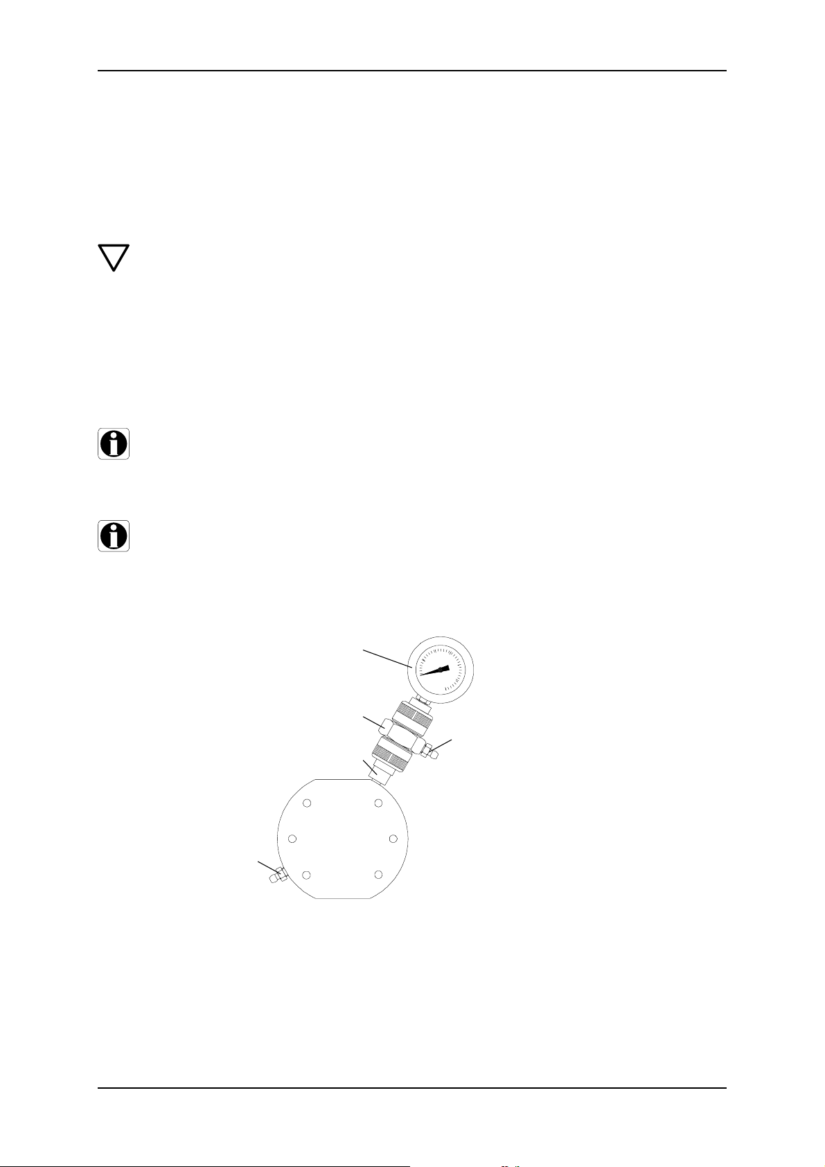
4.1.3 Double diaphragm system / Diaphragm breakage signal (optional)
General
The piston diaphragm and high-tech dosing pumps with drift-free diaphragm breakage
signal are equipped with:
• Dosing head with PTFE double diaphragm system and
• ball check valve with built-in contact manometer
Double diaphragm system
Dosing pumps with a double diaphragm system with no diaphragm breakage signal have
no manometer. In this case the ball check valve is fitted with a locking unit, order No. 541-
013. The valve however can be retrofitted with a contact manometer.
Ball check
In order for the diaphragm breakage signal to work and to protect the diaphragms, the
gap must be fully deaerated. Dosing heads with a double diaphragm are equipped with a
ball check valve (T), to prevent air from flowing back during the filling and deaeration process (2u).
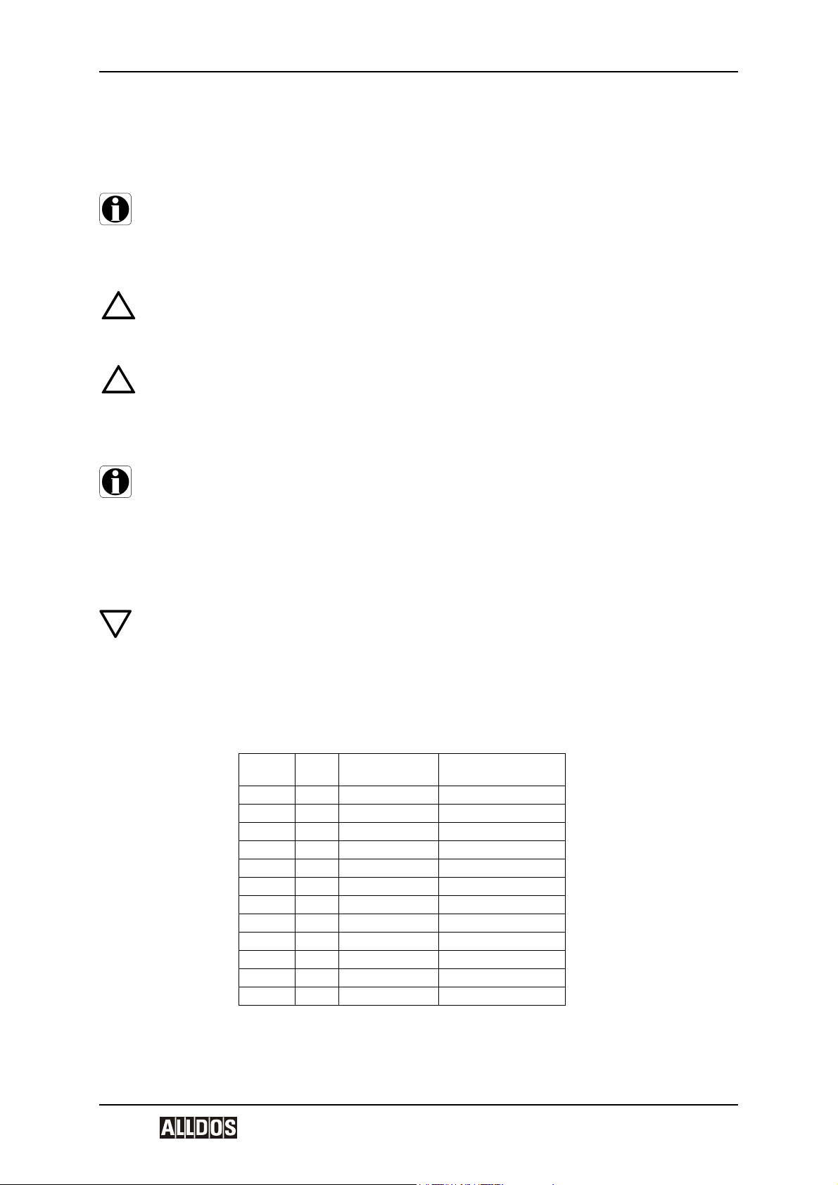
S Contact manometer
T Ball check
2)
6s
U Connection piece
3u
2) For dosing heads with a
double diaphragm with no contact manometer (no diaphragm
breakage signal), a locking unit
2u
(order number 541-013) is fitted
instead of the contact manometer.
3u
S
5s
4u
U
5u
T
Functioning of the diaphragm breakage signal
The check valve and intermediate gap of the diaphragms are filled with a separating
agent (paraffin oil) at the factory and are set in such a way during start-up on the test
stand, that there is always a hydraulically separated equilibrium between the valve and
16 15.720039-V1.0
KM 254 en Product Description and Accessories
diaphragm gap (the manometer indicates “0” when the pump is running and when it is
stopped).
If one of these diaphragms breaks, the dosing or hydraulic medium penetrates into the
intermediate gap and, when the ball is removed, into the valve. The system pressure is
therefore impinged on the valve and the contact manometer is activated. Depending on
the design of the system, the electrically isolated reed contact can trigger an alarm device
or the pump can be switched off.
The contact is triggered at the preset pressure as is shown in the table below:
Part number of
manometer Description/Use Set pressure
!
Warning
541-011
541-011.1
541-012
541-012.1
for pumps up to10 bar
manometer 0 - 10 bar
for pumps up to10 bar
flameproof manometer 0 - 10 bar
for pumps 16 to 100 bar
manometer 0 - 100 bar
for pumps 16 to 100 bar
flameproof manometer 0 - 100 bar
1,5 bar
1,5 bar
10 bar
10 bar
The contact manometer (Ex) in explosion protected version with post switch
should be used if the pump is fitted with a flameproof motor.
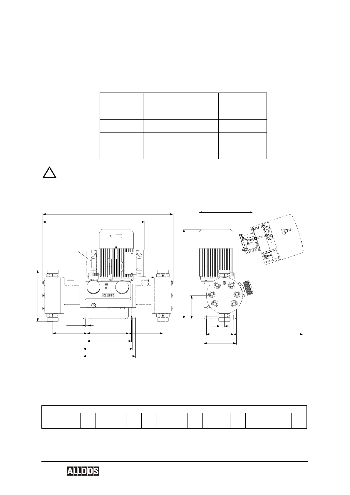
4.2 Dimensional Drawing
h
a
Z1
b
e
g
∅ 9mm
k
Dimensions
Type
KM 254 436 492 156 252 207 185 260 126 718 10 185 235 413 180 225 300
Dimensions in mm
abcdef fxghjkl l’nmmx
f
fx
m
mx
Z1 for double pump, motor turned by 180°
fx, mx for double pumps
l for electrical stroke adjustment
l’ or pneumatic stroke adjustment
k
d
j
c
n
l / l'
V1.0 17

4.3 Weight
KM 254 en
Type Dosing Head Material
KM 254
4.4 Stroke volume
Type
KM 254 31,6 30 —
4.5 Versions
4.5.1 Dosing heads: Materials and Additional Features
For all dosing heads:
• Diaphragm material: PTFE
• with no manual deaeration
Index No.
D000 PVC — —
D001 V4A — —
D002 PP — —
D003 PVDF — —
D004 Hastelloy C — —
D050 V4A — liquid heating
D060 PVC
D061 V4A —
D062 PP —
D063 PVDF —
D064 Hastelloy C —
D360 PVC
D361 V4A —
D362 PP —
D363 PVDF —
D364 Hastelloy C —
Weight [kg]
Single / Double pump
PVC, PP, PVDF 27 32
1.4571, 2.4610 32 42
Stroke volume [cm
10bar 16 bar 25 bar
Dosing
Head
MBS Heating flange
with double diaphragm
system for diaphragm
breakage signal
with double diaphragm
system for diaphragm
breakage signal
Contact manometer
in flameproof version
3
]
—
—
4.5.2 Valves: Materials and Additional Features
For KM 254, pn 10 bar:
• Nominal width DN 20
• Screwed connection 1 1/4“
Index No. Valve Body Gasket Valve Ball Seat Description
R000 PVC Viton Glass PTFE
R001 V4A Viton Stainless steel Stainless steel
R002 PP Viton Glass PTFE
R003 PVDF Viton PTFE PTFE
R006 PTFE PTFE Ceramics PTFE
R009 PVDF PTFE PTFE PTFE
R014 PVC EPDM PTFE PTFE
R020 PVC Viton Glass PTFE spring-loaded
R021 V4A Viton Stainless steel Stainless steel spring-loaded
R022 PP Viton Glass PTFE spring-loaded
R024 PVC EPDM Stainless steel Stainless steel spring-loaded
18 15.720039-V1.0

KM 254 en Product Description and Accessories
Index No. Valve Body Gasket Valve Ball Seat Description
R028 PVDF Viton PTFE PTFE spring-loaded
R029 PVDF PTFE PTFE PTFE spring-loaded
R033 V4A Viton Hastelloy 2.4607 spring-loaded
R046 PVC EPDM Stainless steel Stainless steel
R301 V4A Viton Stainless steel Stainless steel for abrasive media
R401 V4A Viton Stainless steel Stainless steel up to 16 bar
R401 V4A Viton Hastelloy C Hastelloy C up to 16 bar
!
Warning
Risk of malfunction or damage to the device!
The resistance of the parts that come into contact with the media depends on the
media, media temperature and operating pressure. Ensure the parts that come into
contact with the media are chemically resistant to the dosing medium in operating
conditions!
Observe the manufacturer's safety instructions when handling chemicals!
Note
Further information on resistance with regard to the medium, medium temperature
and operating pressure is available on request.
4.6 Materials
Pump Housing Material
Pump
Pump housing Al 226
4.7 Data of contact manometer for MBS (optional)
The contact manometer have a reed switch with electrically isolated contact output, maximum switching power 10 W for DC current or 10 VA for AC current. The maximum switching voltage is 100 V, maximum switching current 0.5 A.
The switching function is set up as an NC contact, i.e. if the diaphragm breaks, the current
circuit is interrupted.
The manometer has a 2 m long cable.
4.8 Installation Location
4.8.1 Space Required for Operation and Maintenance
The pump must be placed where it is freely accessible for operation and maintenance work.
Maintenance work must be carried out regularly on the dosing head and the valves.
• Provide sufficient space for removing the dosing head and the valves.
4.8.2 Permissible Ambient Influences
Permissible
0 °C to + 40 °C (for an installation height up to 1000 m over NN
ambient
temperature
Permissible
relative humidity: 70% at 40 °C, 90% at 35 °C
humidity
Caution
Risk of malfunction or damage to the device!
Pumps with electronics are only suitable for indoor use!
Do not install outdoors!
V1.0 19

4.8.3 Underground
The pump must be mounted on a flat surface.
KM 254 en
20 15.720039-V1.0
KM 254 en Installation
5 Installation
5.1 Mounting
Mount the pump on a console or pump foundation using 4 screws.
Note
Make sure that the flow runs in the opposite direction to gravity.
5.2 General Information on Installation
!
Warning
Observe the specifications for the installation location and range of application
described in the “General” section.
!
Warning
Errors, incorrect operation or faults on the pump or system can lead, for example,
to excessive or insufficient dosing, or the permissible pressure may be exceeded.
Possible errors, faults or damage which may result from this must be evaluated by
the operator and appropriate precautions must be taken to avoid them!
Note
Caution
A positive pressure difference of 2 bar min. is required between the suction valve
and the pressure valve in order for the dosing pump to operate correctly. If the total
counterpressure (at the dosing point) and geodetic height difference between the
suction valve and the dosing point is less than 2 bar (20 m WS), a pressure
retention valve must be installed directly in front of the dosing point.
5.2.1 Approximate values when using pulsation dampers
Risk of damage to the system! We always recommend using pulsation dampers for
large high-speed pumps!
Since the pulsation is influenced by many factors, a system-specific calculation is
essential, e.g. on request with our calculation program.
The following table indicates the approximate values, and for which suction line length
suction pulsation dampers are required. The values relate to 50 Hz operation where water
or similar liquids are used as the dosing medium.
Type
Stroke
254-50 26 DN 20 8
254-102 54 DN 20 8
254-143 75 DN 20 5
254-175 92 DN 20 3
254-213 112 DN 20 1,5
254-291 153 DN 20 1
254-46 26 DN 20 8
254-97 54 DN 20 8
254-136 75 DN 20 5
254-166 92 DN 20 3
254-202 112 DN 20 1,5
254-276 153 DN 20 1
value
Nominal width of
suction line
Maximum suction line
length [m]
V1.0 21

5.2.2 Installation Examples and Tips
Picture of optimal installation
KM 254 en
8i
1i
1i Dosing tank
2i Electric agitator
3i Extraction device
4i Suction pulsation damper
5i Dosing pump
6i Overflow valve
7i Pressure retention valve
8i Pulsation damper
9i Measuring glass
10i Injection unit
2i
7i
max. 1m
6i
4i
3i
9i
10i
5i
13i
6i
p
10i
Tank installation:
• For non-degassing media with viscosity similar to
water, the pump can be mounted onto the tank
(observe the admissible suction height).
Preferable for flooded suction.
For dosing media which tend to sedimentation:
• Install a suction line with filter (13i) in a way ensuring
that the suction valve remains several centimetres a
bove the botton of the tank.
22 15.720039-V1.0

KM 254 en Installation
7i
p≥ 2 bar
Pressure retention valve
With open outflow of the dosing medium or low counterpressure:
A positive pressure difference of at least 2 bar has to exist between the counterpressure at the injection point and the pressure of the dosing medium at the suction valve of the dosing
pump.
If this cannot be guaranteed:
• Install a pressure retention valve (7i) directly in front of the
outlet or the injection unit.
p
1
p2 - p
1
1 bar
_
>
Pressure retention valve
To avoid the siphon effect:
p
2
• Install a pressure retention
valve in the dosing line and, if
14i
p
6i
Overflow valve
To protect the dosing pump and the pressure line
10i
against:
necessary, a solenoid valve
(14i) in the suction line.
• Install an overflow valve (6i) in the pressure line.
11i
p
6i
For volatile media:
• flooded suction
10i
• Install a filter in the suction line to prevent the valves
being contaminated.
To install the suction line:
• Keep the suction line as short as possible, avoid a tangled suction line
• If necessary, use swept bends
instead of elbows.
• Always lay the suction line rising to
the suction valve of the dosing pump.
• Avoid loops which cause air bubbles.
For easy deaeration of the dosing head:
12i
Install a ball valve (11i) with bypass line (back to the dosing tank)
immediately behind the pressure valve.
In case of long pressure lines:
• Install a check-back valve (12i) into the dosing line.
V1.0 23

KM 254 en
For suction-side installation
4i
8i
• Depending on the pump type and line length, it
may be necessary to use a suction pulsation
damper (4i).
Observe the “Approximate values when using
pulsation dampers” auf Seite 21 and if necessary
request a system-specific calculation from our
calculation program.
For pressure-side installation
• Depending on the pump type and line length, it may be
necessary to use a pulsation damper (4i) on the
pressure side.
For rigid pipework and line length > 2m, for flexible
pipework and line length > 3m, depending on the
pump type and size, use pulsation dampers (8) to protect the system.
Caution
Risk of damage to the system! We always recommend using pulsation dampers for
large high-speed pumps!
Since the pulsation is influenced by many factors, a system-specific calculation is
essential, e.g. on request with our calculation program.
24 15.720039-V1.0

KM 254 en Installation
5.3 Tube/Pipe Lines
5.3.1 General
!
Warning
The resistance of the parts that come into contact with the media depends on the
media, media temperature and operating pressure. Ensure the parts that come into
contact with the media are chemically resistant to the dosing medium in operating
conditions!
Only use the specified line types! All lines must be free from strain! If necessary,
use swept bends instead of elbows, avoid loops and buckles in the tubes! Ensure
the suction line is as short as possible to avoid cavitation!
To protect the system against excessive build-up of pressure:
Install an overflow valve in the pressure line.
Flow must run in the opposite direction to gravity!
!
Warning
Observe the manufacturer's safety instructions when handling chemicals!
5.3.2 Connecting the Suction and Pressure Lines
• Connect the suction line to the suction valve.
• Connect the pressure line to the pressure valve.
Note
Install suction line in the tank so that the foot valve remains approximately 5 to 10
cm above the bottom of the tank.
When connecting hose lines
• Push the hose firmly onto the connection nipple
and depending on the connection, secure using a
connection counterpart or hose support clip.
• Fit gasket.
• Screw onto the valve using the union nut.
When connecting pipe lines to DN 20
• Depending on the pipe material and connection,
glue it (PVC), weld it (PP, PVDF or stainless
steel) or press it in (stainless steel).
• Fit gasket.
• Screw onto the valve using the union nut.
5.3.3 Connecting a liquid-heated dosing head (optional)
As an option, liquid-heated dosing heads are available in stainless steel version.
V1.0 25

2f
2f1
Ø10
40
2f Dosing head, liquid heated
2f1 Hose nipple, DN10 connection
Demands placed on heating liquid:
• The heating liquid must not attack stainless steel.
• maximum permissible pressure: p
• maximum permissible temperature: T
max
= 3 bar
= 100 °C
max
KM 254 en
26 15.720039-V1.0

KM 254 en Electrical Connections
6 Electrical Connections
Warning
Electrical connections should only be connected by qualified personnel!
Before connecting the power supply cable and the relay contacts: Disconnect the
mains voltage!
Observe the local safety regulations!
The pump housing must only be opened by personnel authorised by ALLDOS!
Protect the cable connections and plugs against corrosion and humidity.
Only remove the protective caps from the sockets that are being used.
6.1 Electrical servomotor (optional)
To connect the servomotor to the mains supply, please refer to the instructions for the
servomotor.
6.2 Electronic stroke preset counter (optional)
To connect the stroke preset counter to the mains supply, please refer to the instructions
for the stroke preset counter.
6.3 Electrically heated dosing head (optional)
2e
2e Dosing head, electrically heated
2e1
2e2
2e3
To connect the temperature controller to the mains supply, please refer to the instructions
for the electric temperature controller.
6.4 Diaphragm control (optional)
2e1 Sensor
2e2 Heating
2e3 Power supply
!
Warning
Pumps in explosion protected version with diaphragm breakage signal are fitted
with a contact manometer in explosion protected version. It must be grounded.
Connecting the earthing cable (4u) see diagram.
V1.0 27
S Contact manometer
5s Union nut
6s Contact output
T Ball check
U Connection piece
2u Deaeration screw
3u O-rings
4u Connection for earthing cable
5u Union nut
*2) or locking unit
5s
4u
5u
S
6s
3u
2)
U
2u
3u
T
6.5 Connecting the Power Supply Cable
Warning
Disconnect the mains voltage before connecting the power supply cable!
Before connecting the power supply cable, check that the mains voltage specified
on the type plate corresponds to the local conditions!
Do not make any changes to the mains cable or plug!
KM 254 en
!
!
Caution
The pump can be automatically started by connecting the mains voltage!
Warning
The assignment between the plug-and-socket connection and the pump must be
labelled clearly (e.g. by labelling the socket outlet).
• Do not switch on the mains voltage until you are ready to start the pump.
Warning
A clearly labelled all-pole isolating switch with a contact opening width of at least 3
mm should be installed between the pump and the mains.
Connect the motor to the mains in accordance with local electrical installation regulations
as is shown on the terminal connection plan (on the lid of the connection box).
Warning
The specified degree of protection can only be ensured, if the mains cable is connected to the same degree of protection.
Caution
Observe direction of rotation!
To protect the motor, install a motor protecting switch or motor contactor, and set
the bimetal relay to the nominal current of the motor for the present voltage and frequency.
This is also necessary for versions with Etron Profi Electronics!
28 15.720039-V1.0

KM 254 en Start-up/Shutdown
7 Start-up/Shutdown
7.1 Safety Information
!
Warning
When dosing dangerous media, observe the corresponding safety precautions!
When working on the dosing head, connections or lines:
wear the necessary protective clothing (goggles, gloves)!
Before removing the dosing head, valves and media lines, empty any remaining
medium in the dosing head into a driptray by carefully unscrewing the suction
valve.
Do not open the pump!
Repairs must only be carried out by authorised specialists!
Caution
Observe flow direction (arrow) of valves!
Tighten plastic valves by hand only. Risk of damage!
7.2 Initial Start-Up/Subsequent Start-Up
7.2.1 Checks Before Start-Up
• Check all electrical connections are correct.
• Check that the mains voltage specified on the type plate corresponds to the local conditions!
• Check all connections are secure and tighten, if necessary.
• Check fixing screws on the dosing head are tightened with the specified torque and
tighten, if necessary.
!
Tighten the dosing head screws crosswise using a torque wrench:
Torque:
50 - 54 Nm for KM 254
7.2.2 Oil filling
Note
The pump is checked at the factory, and the oil is drained for shipping purposes.
Before start-up, add the special oil which is provided.
The piston flange is filled with oil for easy start-up. The stroke adjustment button
must only be adjusted if the gear oil has been added, otherwise the oil will leak
from the piston flange.
1. Unscrew and remove the aeration screw and oil-level gauge (F).
2. Slowly add the hydraulic oil that is provided through the opening of the filling screw
(F), until the oil reaches the mark on the oil-level gauge.
3. Set the stroke adjustment button (L) to “0”.
7.2.3 Filling the dosing head for the initial start-up for systems without dosing medium flooded suction
Warning
When dosing dangerous media, observe the corresponding safety precautions!
When working on the dosing head, connections or lines:
wear the necessary protective clothing (goggles, gloves)!
As assisting suction for systems without dosing medium flooded suction, you can fill the
dosing head with dosing medium before the initial start-up:
1. Unscrew the pressure valve (3b).
2. Add the dosing medium to the dosing head (2).
3. Screw the pressure valve (3b) back in.
V1.0 29

Caution
KM 254 en
Observe arrow for the pressure valve (for flow direction)!
7.2.4 Start-Up/Subsequent Start-Up
M M
F
3b
1l
L
1q
2
1. Connect the electrical power supply.
2. Depending on the installation, start the pump where possible without counterpressure.
See installation example for easy deaeration of the dosing head in the section on ’Installation’.
3. Set the stroke adjustment button (L) to 0 %.
4. Run the pump for approx. 5 minutes.
5. Checking the oil level.
5.1 Set the stroke adjustment button (L) to 40 %.
5.2 Run the pump for approx. 10 minutes with a stroke adjustment of 40%.
5.3 Switch off pump, check the oil level and add oil if necessary.
5.4 Fit the oil filling screw (F) and the oil-level gauge back on.
– The pump is now ready to operate.
1q Dosing head screws
2 Dosing head
3b Pressure valve
F Oil filling screw
L Stroke adjustment button
1l Cover for stroke adjustment
button
M Pressure relief valve
Note
Caution
Caution
The rod length of the oil level gauge is
for KM 254 35 mm; immersion depth to marking approx. 5 mm.
Check the oil level at least every 2 weeks and add oil if necessary.
Only use original ALLDOS gear oil!
Pump Type Order No. Description
KM 254 single 555-302 3,5 l DHG 68
KM 254 double 555-303 4,5 l DHG 68
7.2.5 After start-up
Following initial start-up and after each time the diaphragm is changed, tighten the
fixing screws on the dosing head:
After approximately 6 - 10 working hours or two days, tighten the dosing head
screws crosswise using a torque wrench.
Torque:
50 - 54 Nm for KM 254
30 15.720039-V1.0

KM 254 en Start-up/Shutdown
7.3 Setting the pressure relief valve
If the written agreement does not specify a system-specific opening pressure, then the
pressure relief valve is set to a slightly greater opening pressure than the bleed pressure
for the pump. It can however be set by the customer to a smaller opening pressure.
Opening pressure of the pressure relief valve
Bleed pressure of
the pump [bar]
10 13
16 18
Setting the opening pressure
Opening pressure of the
pressure relief valve [bar]
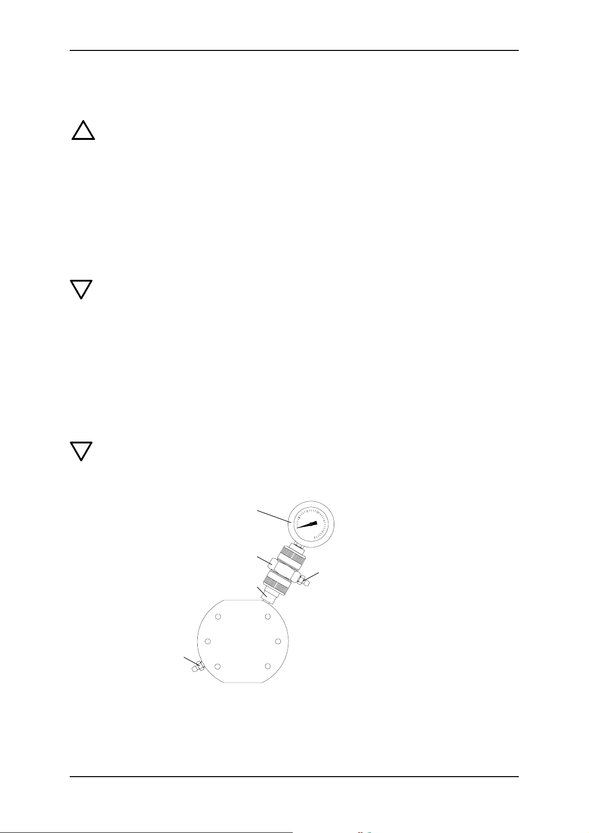
To do so, a manometer must be installed in the
pressure line and behind the manometer, a shutoff valve.
To set the pressure relief valve, use a screwdriver.
Set the pressure relief valve as follows:
Caution
Risk of damage to the pump or system! The pressure relief valve looses its
function through blocking, and can produce pressures of several hundred bar in
the pump or system. Do not block the pressure relief valve during adjustments!
5. Close the cover of the pressure relief valve again.
6. Open the shut-off valve after the manometer.
7.4 Zero Point Adjustments
7.4.1 Adjusting the zero point for system pressures up to 100 bar
1m
2m
1. Close the shut-off valve after the manometer.
2. Remove the cover (1m) of the pressure relief
valve.
3. Start up pump.
4. Using the screwdriver, slowly turn the adjusting
screw (2m) of the pressure relief valve anticlockwise, until the desired opening pressure is obtained.
The zero point of the dosing pump is factory-set to a slightly smaller counterpressure than
the bleed pressure of the pump. If the operating counterpressure deviates considerably
V1.0 31
from this value, adjusting the zero point will ensure that the values are more precise.
Counterpressure for zero point setting of the pump at the factory
Bleed pressure of
the pump [bar]
10 3
16 3
7.4.2 Adjusting the Zero Point
KM 254 en
Counterpressure for zero point setting
of the pump at the factory [bar]
!
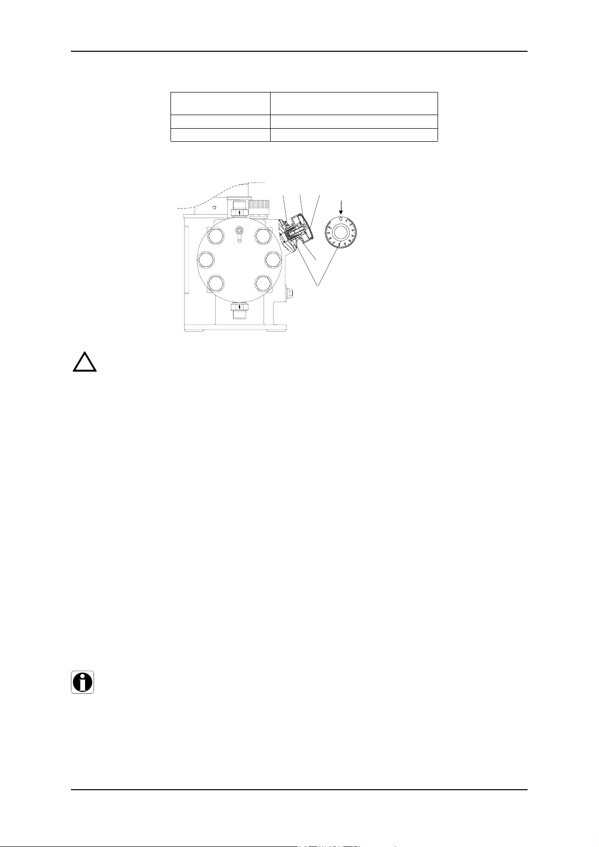
Warning
3l 2l 1l
L
4l
3l
L Stroke adjustment button
1l Cover
2l Locking screw
3l Screw
4l Scale ring
When dosing dangerous media, observe the corresponding safety precautions!
When working on the dosing head, connections or lines:
wear the necessary protective clothing (goggles, gloves! Always adjust the value
with the pressure line connected and with operating counterpressure.
1. Fit a measuring device on the suction side, e.g. place the suction line in a graduated
measuring beaker.
2. Set dosing flow to 15%.
3. Remove cover (1l) from stroke adjustment button (L).
4. Use a screwdriver to loosen the locking screw (21) by approximately 2 rotations.
5. Switch on the pump.
6. Turn the stroke adjustment button slowly towards the zero point, until the dosing (the
liquid level falls) stops in the measuring device.
7. Switch off the pump.
8. Set the scale ring (4l) to zero
8.1 Loosen the screw (3l) in the scale ring (4l) slightly using an Allan wrench M3,
8.2 Turn the scale ring (4l) until both “0” are the same on the scale and scale ring.
8.3 Tighten screw (3l).
9. Depending on the application, tighten the locking screw (21) so that the stroke adjustment button can still be turned/cannot be turned any more.
10. Replace cover (1l).
7.5 Operating the pump
Note
When operating the pump, refer to the section “Operating the pump”, “Operating
the pump electronics “ (only for Etron Profi Electronics), as well as “Maintenance”
and if necessary for troubleshooting, the section “Possible faults”.
32 15.720039-V1.0
KM 254 en Start-up/Shutdown
7.6 Shutdown
!
Warning
When working on the dosing head, connections or lines:
Risk of injuries! Wear the necessary protective clothing (goggles, gloves)!
Do not allow any chemicals to leak from the pump. Collect and dispose of all chemicals correctly!
Note
If possible, rinse the dosing head before shutting down the pump, e.g.
by supplying it with water.
7.6.1 Switching Off/Uninstalling
• Switch off the pump and disconnect it from the mains.
• Depressurise the system.
• Take suitable steps to ensure that the returning dosing medium is safely collected.
• Carefully remove all lines.
• Uninstall the pump.
7.6.2 Cleaning
• Rinse all parts that have come into contact with the medium very carefully:
• Lines
• Valves
• Dosing Head
• Diaphragm
• Remove any trace of chemicals from the pump housing.
7.6.3 Storage
When you store the pump:
After cleaning (see above)
• Carefully dry all parts and reinstall the dosing head and valves
or
• Change the valves and diaphragm.
See “Maintenance” section.
7.6.4 Disposal
When you dispose of the pump:
After cleaning (see above)
• Dispose of the pump in accordance with the relevant regulations.
V1.0 33
8 Operating the Pump
8.1 Switching On/Off
Caution
Before switching on the pump, check that it is installed correctly. See the “Installation” and “Start-Up” sections.
8.1.1 Switching On the Pump
• Switch on the mains voltage
8.1.2 Switching Off the Pump
• Switch off the mains voltage.
8.2 Setting the dosing capacity
KM 254 en
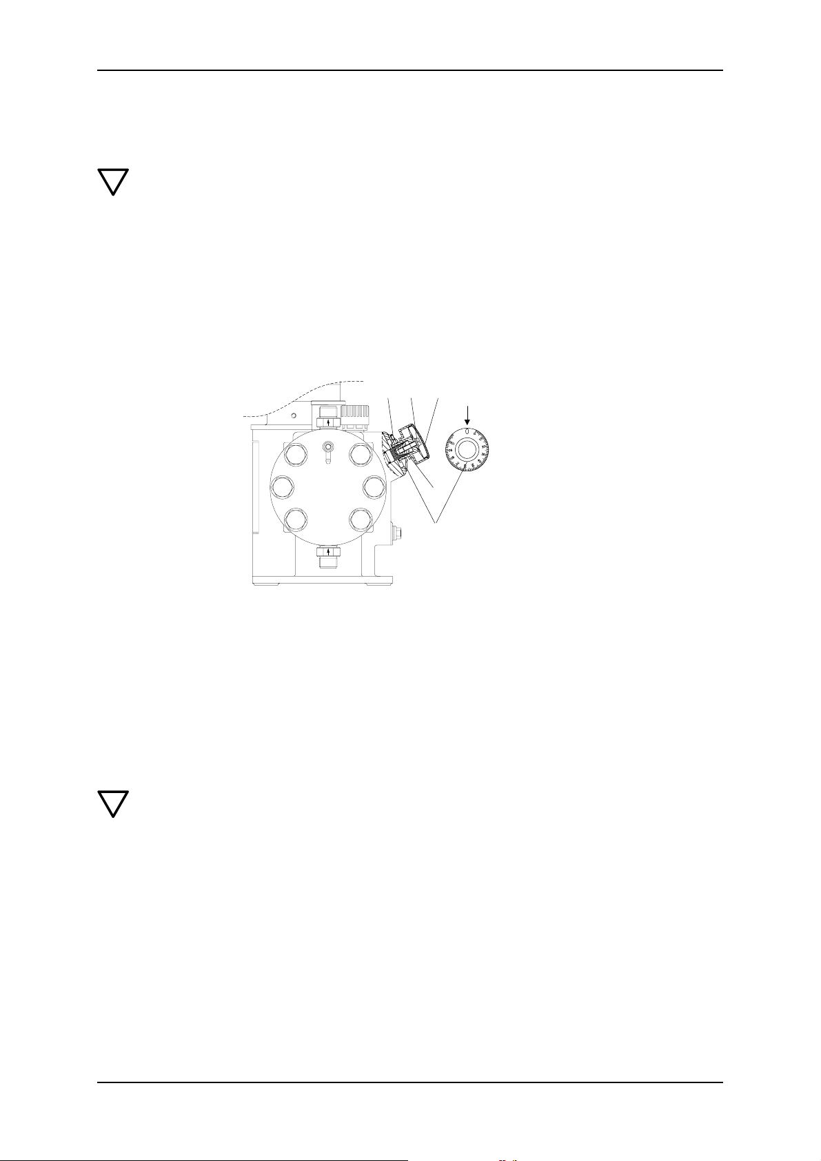
3l 2l 1l
L
4l
3l
L Stroke adjustment button
1l Cover
2l Locking screw
3l Screw
4l Scale ring
8.2.1 Setting the dosing flow and locking the stroke adjustment button
1. Remove cover (1l) from stroke adjustment button (L).
2. Use a screwdriver to loosen the locking screw (21) by approximately 2 rotations.
3. Increase/reduce the dosing flow while the pump is running.
3.1 Slowly turn the stroke adjustment button to the left / right to set the desired
dosing volume.
4. Depending on the application, tighten the locking screw (21) so that the stroke adjustment button can still be turned/cannot be turned any more.
5. Replace cover (1l).
Caution
Pump cannot be operated if the stroke adjustment button is fully open! Depending
on the pump adjustment, this value may already be < 100 % on the scale display
for system pressures of > 100 bar.
Open the stroke adjustment button completely and then close by approx. 10% in
order to set the dosing flow to 100 %.
8.3 Electrical servomotor (optional)
To operate the servomotor, please refer to the instructions for the servomotor.
8.4 Electronic stroke preset counter (optional)
To operate the stroke preset counter, please refer to the instructions for the stroke preset
counter.
8.5 Electrically heated dosing head (optional)
To operate the temperature controller, please refer to the instructions for the temperature
34 15.720039-V1.0

KM 254 en Operating the Pump
controller.
V1.0 35
9 Maintenance
9.1 General Notes
!
Warning
When dosing dangerous media, observe the corresponding safety precautions!
When working on the dosing head, connections or lines: Wear the necessary protective clothing (goggles, gloves)!
Do not open the pump!
Repairs must only be carried out by authorised and qualified personnel!
Switch off the pump and disconnect it from the mains before carrying out maintenance work and repairs!
Before removing the dosing head, valves and media lines, empty any remaining
medium in the dosing head into a driptray by carefully unscrewing the suction
valve.
Caution
Observe flow direction (arrow) of valves!
Tighten plastic valves by hand only. Risk of damage!
KM 254 en
9.2 Diaphragm breakage control for diaphragm breakage signal
If a diaphragm breakage signal (MBS) occurs, you should first of all check whether an
error has been displayed, as different external factors such as for instance, the heating of
hydraulic or dosing medium can cause the cracked medium to be displaced into the valve,
thereby causing an error to occur. Checks after an MBS:
1. Briefly open the MBS deaeration screw (2u) and then close it again.
2. Switch on the pump
3. If an MBS reoccurs after a short period of time, then a diaphragm has broken.
Caution
After a diaphragm breakage, replace the diaphragms and clean the check-back
valve, see section on “Replacing the diaphragm for dosing head with double diaphragm”.
S
U
2u
T
S Contact manometer
T Ball check
U Connection piece
1u Filling screw
2u Deaeration screw
1u
9.3 Intervals for cleaning and maintenance
Check the oil level and add oil if necessary.
• Check the oil level every 2 weeks and add oil if necessary.
36 15.720039-V1.0

KM 254 en Maintenance
Clean the valves.
• At least every 12 months or after 4000 operating hours, or
• if the pump isn’t performing, or
• in the event of an error.
Clean the valves and replace if necessary (for stainless steel valves: inner parts of valve)
Change diaphragms and gear oil.
• At least every 12 months or after 8000 operating hours, change the dosing medium
and gear oil,
• in dusty installation site, change gear oil every 3000 operating hours.
Clean ball check of the double diaphragm
• after a diaphragm breakage, remove the ball check immediately and clean it.
Note
Only clean the ball check after a diaphragm breakage!
9.4 Checking the oil level
Caution
Check the oil level at least every 2 weeks and add oil if necessary.
Note
The rod length of the oil level gauge is
for KM 254 35 mm; immersion depth to marking approx. 5 mm.
9.5 Cleaning the suction and pressure valves
!
Warning
When working on the dosing head, connections or lines: Wear the necessary protective clothing (goggles, gloves)!
Before removing the dosing head, valves and media lines, empty any remaining
medium in the dosing head into a driptray by carefully unscrewing the suction
valve.
Nominal width DN 20
• Screwed connection 1 1/4“
• Stainless steel/plastic
• optional spring-loaded
Clean suction and pressure valves as follows:
1. Unscrew valves.
2. Unscrew screw parts and valve set using round pliers.
3. Dismantle inner part (seat, O-ring, balls, ball cages, if necessary spring).
4. Clean all parts, replace any faulty parts.
5. Reassemble valve.
6. Replace O-rings with new ones and screw valve back in.
V1.0 37

KM 254 en
Caution
2)1)
DN 20 valve
optional spring-loaded
1)
stainless steel/
2)
plastic,
The O-rings must be correctly placed in the specified groove.
Observe flow direction (arrow)!
Tighten plastic valves by hand only. Risk of damage!
38 15.720039-V1.0

KM 254 en Maintenance
9.6 Changing the diaphragm and gear oil for dosing head with single diaphragm (no MBS)
!
Warning
When working on the dosing head, connections or lines:
Wear the necessary protective clothing (goggles, gloves)!
The dosing diaphragm should be replaced with each gear oil change.
Before removing the dosing head, valves and media lines, empty any remaining
medium in the dosing head into a driptray by carefully unscrewing the suction
valve.
Caution
Only use original ALLDOS gear oil!
ALLDOS gear oil
Pump Type Order No. Description
KM 254 single 555-302 3,5 l DHG 68
KM 254 double 555-303 4,5 l DHG 68
Note
Collect gear oil in a container and dispose of correctly.
Caution
9.6.1 Drain gear oil
1. Unscrew the stroke adjustment screw (B) and collect gear oil in a container.
2. Screw the lock screw (B) and the new gasket (1b) back in and tighten well.
Risk of leaking and damage caused by oil loss! For each oil change, a new flat gasket (1b) must be used!
F
B Lock screw
1b Gasket
F Oil filling screw
L Stroke adjustment button
L
1b
B
9.6.2 Removing the dosing head
1. Close dosing lines on suction and pressure side and loosen suction and pressure
valve connections.
2. Loosen the 6 dosing head screws (1q with 2q) and remove the dosing head (2).
9.6.3 Replacing a single diaphragm (no MBS)
• Remove the diaphragm, fit new diaphragm (Q) on suction side (see diagram below).
V1.0 39

2q
1q
2
9.6.4 Fitting the dosing head
• Fit the dosing head and tighten the dosing head screws (1q with 2q) crosswise using a
torque wrench.
KM 254 en
1q Dosing head screw
2q Intermediate disk
2 Dosing head
Q Diaphragm
Q
Note
Caution
Caution
Refer to the “Start-up” section for subsequent start-up!
9.6.5 Filling gear oil
Risk of leaking and damage caused by oil loss! For each oil change, a new flat gasket (1b) must be used!
Check that the lock screw (B) is tightened.
1. Unscrew and remove the aeration screw and oil-level gauge (F).
2. Set the stroke adjustment button (L) to “0”.
3. Slowly add the hydraulic oil through the aeration screw opening (F), until the oil reaches the mark on the oil-level gauge.
4. Wait 30 minutes.
5. Run the pump for approx. 5 minutes with a stroke adjustment of 0%.
6. Run the pump for approx. 10 minutes with a stroke adjustment of 40%.
9.6.6 Checking the oil level.
1. Switch off pump, check the oil level and add oil if necessary.
2. Fit the aeration screw and oil-level gauge (F) back on.
Following initial start-up and after each time the diaphragm is changed, tighten the
fixing screws on the dosing head:
After approximately 6 - 10 working hours or two days, tighten the dosing head
screws crosswise using a torque wrench.
Torque:
50 - 54 Nm for KM 254
40 15.720039-V1.0
KM 254 en Maintenance
2
9.7 Replacing the diaphragm for dosing head with double diaphragm
9.7.1 Removing the dosing head
1. Close dosing lines on suction and pressure side and loosen suction and pressure
valve connections.
2. Loosen the 6 dosing head screws (1q with 2q) and remove the dosing head (2).
9.7.2 Replace the double diaphragm.
1. Clean the intermediate disk (3q), sealing rings (4q) and covering rings (5q) - replace
with new ones after a diaphragm has broken.
2. Remove both clamping sleeves (6q) slightly using pliers - replace with new ones after
a diaphragm has broken.
3. Measure the outer wall thickness of both new diaphragms (Q1 and Q2):
s
1 (Q1)
< s
2 (Q2)
.
s1 < s
2
1q Dosing head screw
2q Intermediate disk
2 Dosing head
Q see diagram below
Caution
q
1q
1) The shape of the diaphragm
2
varies depending
on the type of pump.
3q - 5q Q2Q1
1)
Observe correct installation of diaphragms Q1 and Q2 (see diagram)!
Fit the thinner diaphragm (Q1) on eth dosing side and the thicker diaphragm (Q2)
on the oil side/pump side!
4. Fit both new diaphragms (Q1 and Q2) and the parts (3q - 5q) in the correct order, as is
shown in the diagrams (the clamping sleeves (6q) are used for centring purposes).
S
6q
3q
2 5q4q3q4q5q Q2Q1
V1.0 41
Caution
Note
KM 254 en
S Contact manometer (installation position)
Q1 Diaphragm on dosing head side
Q2 Diaphragm on oil side/pump side
3q Intermediate disk
4q Sealing rings
5q Covering rings
6q Clamping sleeves
The paraffin oil between the diaphragms (Q) is connected via the clamping sleeves
(6q) to the contact manometer (S) in order to fill and activate the diaphragm breakage signal. It is able to pass between the diaphragms through the slits in the clamping sleeves and the slits in the intermediate disk.
The clamping sleeves (6q) must therefore be installed in such a way that the slits in
the clamping sleeve face the slits in the intermediate disk (3q) (see above).
9.7.3 Fitting the dosing head
• Fit the dosing head and tighten the dosing head screws crosswise using a torque
wrench.
Refer to the “Start-up” section for subsequent start-up.
Note
9.7.4 Filling the double diaphragm with separating agent
After a diaphragm has broken, the ball check must be cleaned before forng filled
with separating agent. Only clean the ball check after a diaphragm breakage!
After the diaphragm has been replaced for a pump with a double diaphragm, refill the
separating agent between the diaphragm:
S
U
2u
T
1u
S Contact manometer
T Ball check
U Connection piece
1u Filling screw
2u Deaeration screw
1. Set the stroke adjustment button of the pump to 0 %.
2. Open the filling screw (1u) and deaeration screw (2u) by one rotation.
3. Connect the filling hose to the nipple of the filling screw (1u) and, using the dosing
syringe inject the correct amount of paraffin oil that is specified in the table below.
4. Close filling screw (1u), but leave the deaeration screw (2u) open.
5. Start up the pump with a system counterpressure and 40 % stroke adjustment.
42 15.720039-V1.0

KM 254 en Maintenance
6. Only close the deaeration screw (2u) when the separating agent stops flowing. (after
approx. 5 - 10 min)
Note
Once filled with separating agent and after a few operating hours, especially if the
pressure of the manometer is increasing, deaerate again.
Filling quantity of paraffin oil for dosing pumps with a double diaphragm (per dosing head)
Pump Type Filling quantity in ml
KM 254 6
Ordering data for double diaphragm filling components
Order No. Description
555-410 Filling components, set with paraffin oil, throw-away syringe and hose parts
9.7.5 Filling gear oil
Caution
Risk of leaking and damage caused by oil loss! For each oil change, a new flat gasket (1b) must be used!
Check that the lock screw (B) is tightened.
1. Unscrew and remove the aeration screw and oil-level gauge (F).
2. Set the stroke adjustment button (L) to “0”.
3. Slowly add the hydraulic oil through the aeration screw opening (F), until the oil reaches the mark on the oil-level gauge.
4. Wait 30 minutes.
5. Run the pump for approx. 5 minutes with a stroke adjustment of 0%.
6. Run the pump for approx. 10 minutes with a stroke adjustment of 40%.
Caution
Note
9.7.6 Checking the oil level.
7. Switch off pump, check the oil level and add oil if necessary.
8. Fit the aeration screw and oil-level gauge (F) back on.
Following initial start-up and after each time the diaphragm is changed, tighten the
fixing screws on the dosing head:
After approximately 6 - 10 working hours or two days, tighten the dosing head
screws crosswise using a torque wrench.
Torque:
50 - 54 Nm for KM 254
9.7.7 Cleaning the ball check valve
Only clean the ball check after a diaphragm breakage!
V1.0 43

KM 254 en
S Contact manometer
5s Union nut
2)
6s
6s Contact output
T Ball check
3u
U Connection piece
2u Deaeration screw
2u
3u O-rings
4u Connection for earthing cable
3u
5u Union nut
*2) or locking unit
S
5s
4u
U
5u
T
Removing the ball check and contact manometer
1. For pumps and manometers in flameproof version, unscrew the earthing (4u).
2. Hold the connection piece (U) using a screwdriver and unscrew the union nut (3u).
3. Unscrew the ball check (T) from the dosing head.
Clean the ball check
t7
t1 O-ring
t6
t5
t4
t3
t1
t2 Ball check body
t3 Ball
t4 Spring sheath
t5 Pressure spring
t6 Screw part
t7 O-ring
t2
t1
1. Unscrew screw part (t6) using round pliers.
2. Clean all parts, replace any faulty parts.
3. Reassemble ball check.
4. Refit ball check (T).
5. Screw contact manometer (S) and connection piece (U) back on.
6. For pumps and manometers in flameproof version, screw earthing (4u) back on.
Caution
Tighten ball check and connection piece by hand only. Risk of damage!
44 15.720039-V1.0
KM 254 en Possible Errors
10 Possible Errors
Caution
Actions that are taken to overcome faults on the pump and which are not described
in the operation manual, must only be carried out by the service centre!
Fault Diagnosis Cause Remedy
No dosing flow even
at a low
backpressure. (Pump
is running without any
noise).
No dosing flow even
at a low
backpressure.
(pump is running
noisily, although the
overpressure valve
reacted).
Pump does not deliver
or pressure relief
valve opens.
No motor sound or vibrations,
Ventilator is not rotating.
When the aeration screw is
removed, use the oil-level gauge
(F) to observe a calm oil surface,
there is no “sloshing”.
Oil level too low - see oil-level
gauge (F). No reaction of the
overpressure valve, if the suction
line is closed.
No dosing flow at the pressure
side
Overpressure valve reacts
independent from the dosing flow
adjustment (10%-100%).
AMS responds, overpressure
valve reacts independent from the
dosing flow adjustment (10%100%).
AMS responds, overpressure
valve reacts at 100% dosing flow,
when reducing the flow ~10%20% the overpressure valve does
not react any more.
Motor is not running.
Motor runs, but the eccentric
shaft is not rotating, no piston
movement; spiral pin or motor
shaft broken.
Not enough oil in the pump,
air is penetrating the piston
flange through the control
holes.
Dosing head is not filled,
suction line empty, tank empty
Valve at pressure side closed. Open valve.
Backpressure is higher than
the adjusted pressure at the
overpressure valve.
Pressure valve is installed in
the opposite direction of the
flow, observe the arrow at the
valve.
Valve at suction side closed. Open valve.
Suction filter obstructed. Clean suction filter, replace.
Suction valve jammed (does
not open).
Suction valve has a too strong
spring.
Suction valve is installed in
the opposite direction of the
flow, observe the arrow at the
valve.
Dosing head is not completely
deaerated.
Pump is running in cavitation
(dosing liquid with too high
viscosity; dosing liquid with
too high steam pressure at
Operating temperature =
degassing of the liquid;
suction height too high; wrong
design of the system at
suction side).
Diaphragm broken (not
enough oil in the enclosure of
the pump; piston flange).
Pressure valve of pump is
clogged or ball guide in the
valve is worn due to corrosive
or abrasive media.
Connect at power supply,
exchange motor if blown.
Dismantle the motor and eccentric
shaft, replace damaged parts.
Fill in oil, deaerate the pump,
see “Start-up”.
Deaerate dosing head, fill/
exchange (tank) at suction side
Adjust overpressure valve higher,
but only if the pump is designed
for this. Never block the
overpressure valve.
Install pressure valve correctly.
Dismantle and check suction
valve.
Use fitting spring, or use double
ball valve for checking.
Install suction valve correctly.
Fill dosing head completely.
Use a gear with a low stroke
number; use valves with bigger
nominal width; realise admission
pressure on suction side.
Clean and grease well all parts
using oil according to regulations,
then install new diaphragm.
Uninstall pressure valve,
dismantle and clean, or if the bars
of the ball guide are worn, replace
valve.
V1.0 45
Fault Diagnosis Cause Remedy
Suction valve: during the pressure
stroke the dosing liquid flows back
into the suction line.
Pressure valve: during the suction
stroke, the dosing liquid flows back
into the dosing head; the pump
takes in less.
Suction/pressure valves dirty
or leaky.
Clean or exchange valves.
KM 254 en
Dosing flow too small
Pump doses too much
Dosing flow depends very much
on the pressure; if the
backpressure is low, the dosing
flow increases considerably. If the
stroke frequency rises, the dosing
flow increases excessively.
Manometer pressure line.
Especially with stroke frequencies
below 15H/min, e.g. with
frequency converter operation.
Manometer pressure line
Heavy overdose
Overdosing at bigger dosing flow
adjustments and flows.
Too much clearance between
piston and slide valve, or the
stroke frequency of the pump
is too low (too much slip).
Backpressure has seriously
increased; overpressure valve
is adjusted too low.
Degassing valve (M) is not
working properly.
Backpressure has seriously
dropped.
Admission pressure of suction
line > backpressure of
pressure line.
Too big dynamic in the suction
line.
Replace piston and piston slide
valves, use anderes other
hydraulic oil with a higher
viscosity, (mainly for frequency
controller operation and higher
backpressures).
Readjust zeropoint.
Correct setting of the pressure
relief valve.
Replace degassing valve (M), or if
necessary replace with ø8 ball.
Readjust zeropoint.
Install a pressure retention valve.
Mount a suction pulsation damper.
46 15.720039-V1.0
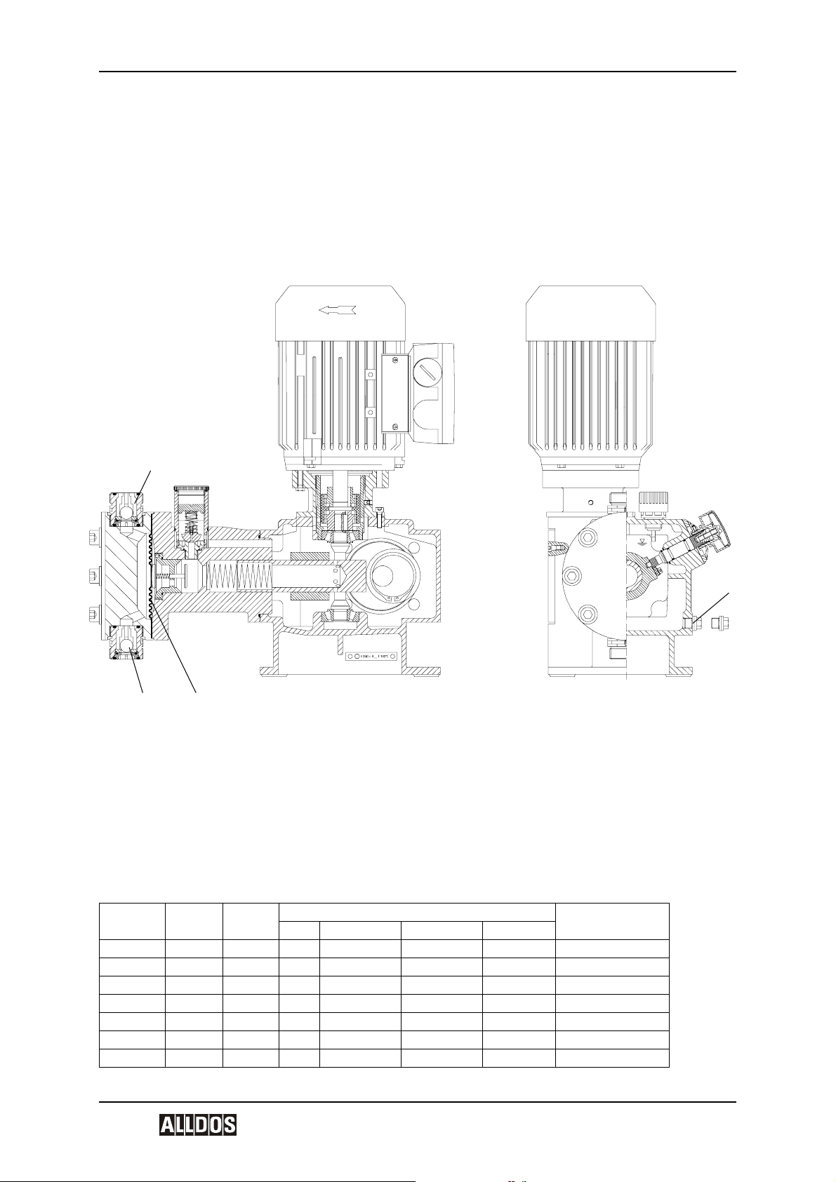
KM 254 en Spare Parts
11 Spare Parts
Manufacturer recommendation
We recommend that you keep some spare parts in stock to ensure that worn parts can be
replaced quickly when necessary.
Two spare parts are required for double pumps.
3b
storage temperature
Permissible
Permissible
humidity
-10 °C to +50 °C
Relative: 80%, maximum
1b
χ
ε
3a Q
A spare part includes the following parts:
1b 2 Flat gaskets
3a, 3b Inner parts for 2 valves
Q 1 dosing diaphragm (for pumps without MBS), or
1 diaphragm set (for pumps with MBS), consisting of diaphragms, intermediate disk, foils,
covering rings and clamping sleeves
Order numbers
Order numbers for spare parts can be found in the table below or can be obtained on
request by indicating the device name of the pump. If you already have a spare part set,
you can reorder it using the same number.
Order
number
553-268 254 DN 20 Glass PTFE Viton
553-269 254 Stainless steel Stainless steel
553-280 254 10,00 bar DN 20 Stainless steel Stainless steel Viton
553-297 254 10,00 bar DN 20 Glass PTFE Viton
553-298 254 10,00 bar DN 20 Glass PTFE Viton
553-299 254 10,00 bar DN 20 PTFE PTFE PTFE / Viton
553-1080 254 10,00 bar DN 20 Hastelloy 2.4607 Viton
Pump
type
Pressure
Nominal width/Valve material
Balls Seat Gasket
Version
V1.0 47
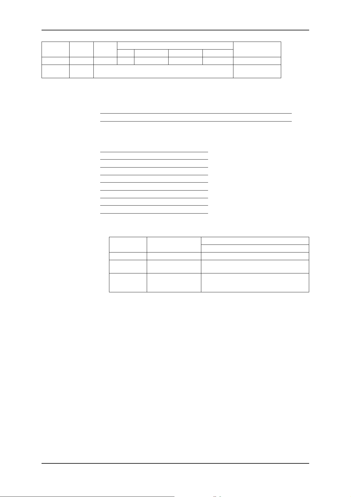
KM 254 en
Order
number
553-1320 254 10,00 bar DN 20 Stainless steel PTFE EPDM
553-407 254 — 2)
Pump
type
Pressure
2) Spare parts set only for replacing diaphragm (e.g. following diaphragm breakage) without valve
parts.
ALLDOS gear oil
Alternative Spezialöle für DHG 68
Nominal width/Valve material
Balls Seat Gasket
Pump type Order No. Description
KM 254 single 555-302 3,5 l DHG 68
KM 254 double 555-303 4,5 l DHG 68
Manufacturer Designation
ARAL Degol BMB 68
BP BP-Energol GR-XP 68
Chevron Chevron NL gear compound 68
ESSO Spartan BP 68
Fina Fina Giran 68
Mobil Oil Mobilgear 626
Texaco Texaco Meropa 68
Shell Tellus 68
elf reductelf SP 68
Version
Diaphragm breakage
safety device
Spare parts for double diaphragm system
Order No.
541-011 up to 10 bar Contact manometer up to 10 bar
541-011.1 up to 10 bar
553-410
Bleed pressure of
pump
Description
Index No.
Contact manometer up to 10 bar
in flameproof protection version
Filling components, consisting of: 0.004 kg
paraffin oil in PE bottle, 2 x 250 mm PE filling hose
4/6 and a graduated throw-away syringe
48 15.720039-V1.0
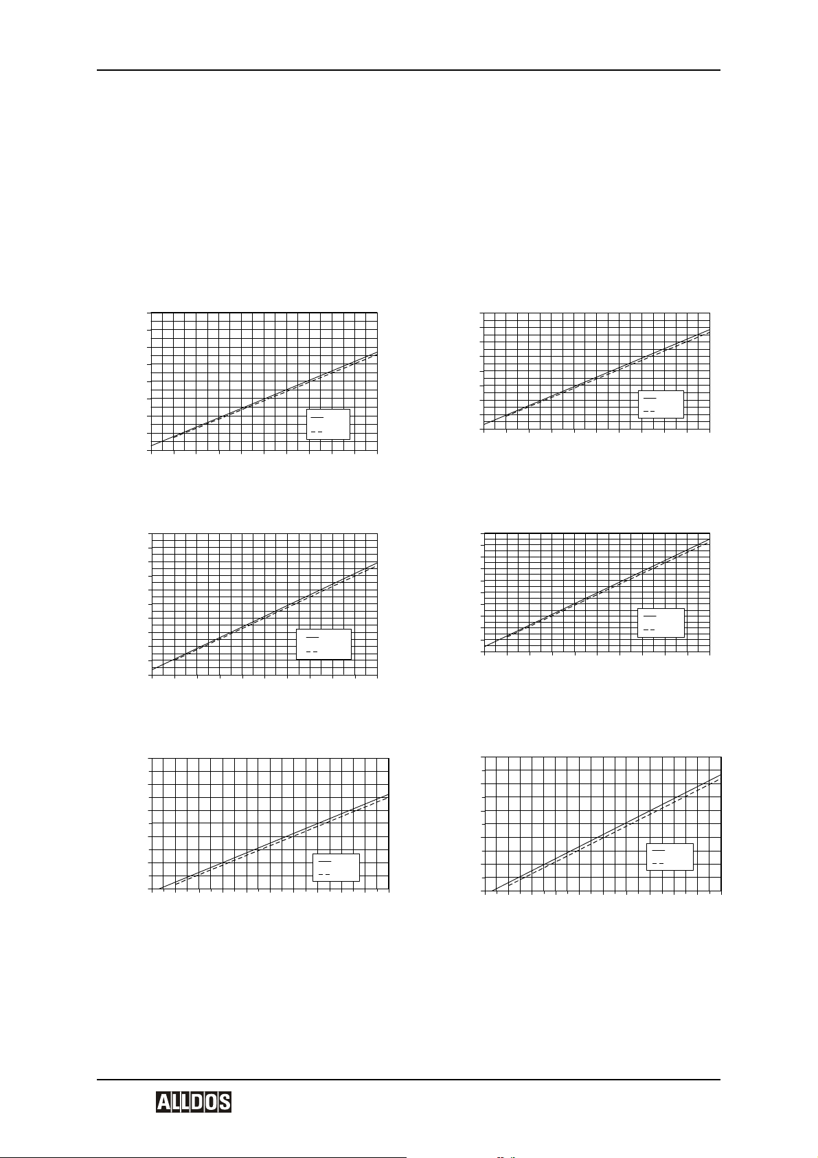
KM 254 en Dosing Curves
12 Dosing Curves
The dosing curves refer to:
• The dosing medium water,
• Zero point of pump Q
Q Dosing flow
Zeropoint of the pump
Q
0
h Stroke length
for specified pressure - see diagram.
0
Q [l/h]
Q [l/h]
254-102 (50Hz) Q0 = 3bar
160
140
120
100
80
60
40
20
3bar
10bar
0
0 102030405060708090100
254-143 (50Hz) Q0 = 3bar
200
180
160
140
120
100
80
60
40
20
3bar
10bar
0
0 102030405060708090100
h [%]
h [%]
Q [l/h]
Q [l/h]
254-102 (60Hz) Q0 = 3bar
160
140
120
100
80
60
40
20
3bar
10bar
0
0 102030405060708090100
254-143 (60Hz) Q0 = 3bar
200
180
160
140
120
100
80
60
40
3bar
10bar
20
0
0 102030405060708090100
h [%]
h [%]
Q [l/h]
254-175 (50Hz) Q0 = 3bar
250
200
150
100
50
3bar
10bar
0
0 102030405060708090100
250
Q [l/h]
200
150
100
50
0
h [%]
254-175 (60Hz) Q0 = 3bar
3bar
10bar
0 102030405060708090100
h [%]
V1.0 49

KM 254 en
Q [l/h]
Q [l/h]
254-213 (50Hz) Q0 = 3bar
300
250
200
150
100
50
3bar
10bar
0
0 102030405060708090100
254-291 (50Hz) Q0 = 3bar
350
300
250
200
150
100
50
3bar
10bar
0
0 102030405060708090100
h [%]
h [%]
Q [l/h]
300
254-213 (60Hz) Q0 = 3bar
250
200
150
100
50
3bar
10bar
0
0 102030405060708090100
h [%]
Q [l/h]
Q [l/h]
254-97 (50Hz) Q0 = 10bar
140
120
100
80
60
40
20
10bar
16bar
0
0 102030405060708090100
254-136 (50Hz) Q0 = 10bar
200
180
160
140
120
100
80
60
40
20
0
0 102030405060708090100
10bar
16bar
h [%]
h [%]
Q [l/h]
Q [l/h]
140
254-97 (60Hz) Q0 = 10bar
120
100
80
60
40
20
10bar
16bar
0
0 102030405060708090100
254-136 (60Hz) Q0 = 10bar
200
180
160
140
120
100
80
60
40
20
0
0 102030405060708090100
10bar
16bar
h [%]
h [%]
50 15.720039-V1.0

KM 254 en Dosing Curves
Q [l/h]
Q [l/h]
250
200
150
100
50
0
0 102030405060708090100
10bar
16bar
254-202 (50Hz) Q0 = 10bar
280
240
200
160
120
254-166 (50Hz) Q0 = 10bar
80
40
0
0 102030405060708090100
10bar
16bar
h [%]
h [%]
Q [l/h]
Q [l/h]
250
200
150
100
50
0
0 102030405060708090100
10bar
16bar
254-202 (60Hz) Q0 = 10bar
280
240
200
160
120
254-166 (60Hz) Q0 = 10bar
80
40
0
0 102030405060708090100
10bar
16bar
h [%]
h [%]
Q [l/h]
320
254-276 (50Hz) Q0 = 10bar
280
240
200
160
120
80
40
0
0 102030405060708090100
10bar
16bar
h [%]
V1.0 51
EC Declaration of Conformity (Translation)
in the context of EC machinery directive 98/37/EC,
EC directive for EMC 89/336/EEC
The design of the product range
Piston Diaphragm Dosing Pumps KM 254
has been developed, constructed and manufactured in compliance with
EC directives 98/37/EC and 89/336/EEC at the sole responsibility of
ALLDOS Eichler GmbH
Reetzstr. 85
D-76327 Pfinztal (Söllingen), Germany
KM 254 en
The following harmonized standards have been applied:
• EN 292-1:1991/ EN 292-2:1991 + A1:1995
• EN 809:1998
• EN 61000-3-11:2000 *
• EN 61000-6-2:2001
• EN 61000-6-4:2001
* with Etron Profi electronics
Pfinztal, 25/10/02
Ewald Diesslin pp Klaus Müller
Managing Director Construction and
Development
Any modifications made to the pump without our approval will invalidate this declaration.
When installing the pump in a machine or system ensure that the machine or system into
which it is installed complies with the provisions of the directives. The pump must not be
started until this has been established.
52 15.720039-V1.0
 Loading...