

All American 225 Operator's Manual
OPERATOR’S MANUAL
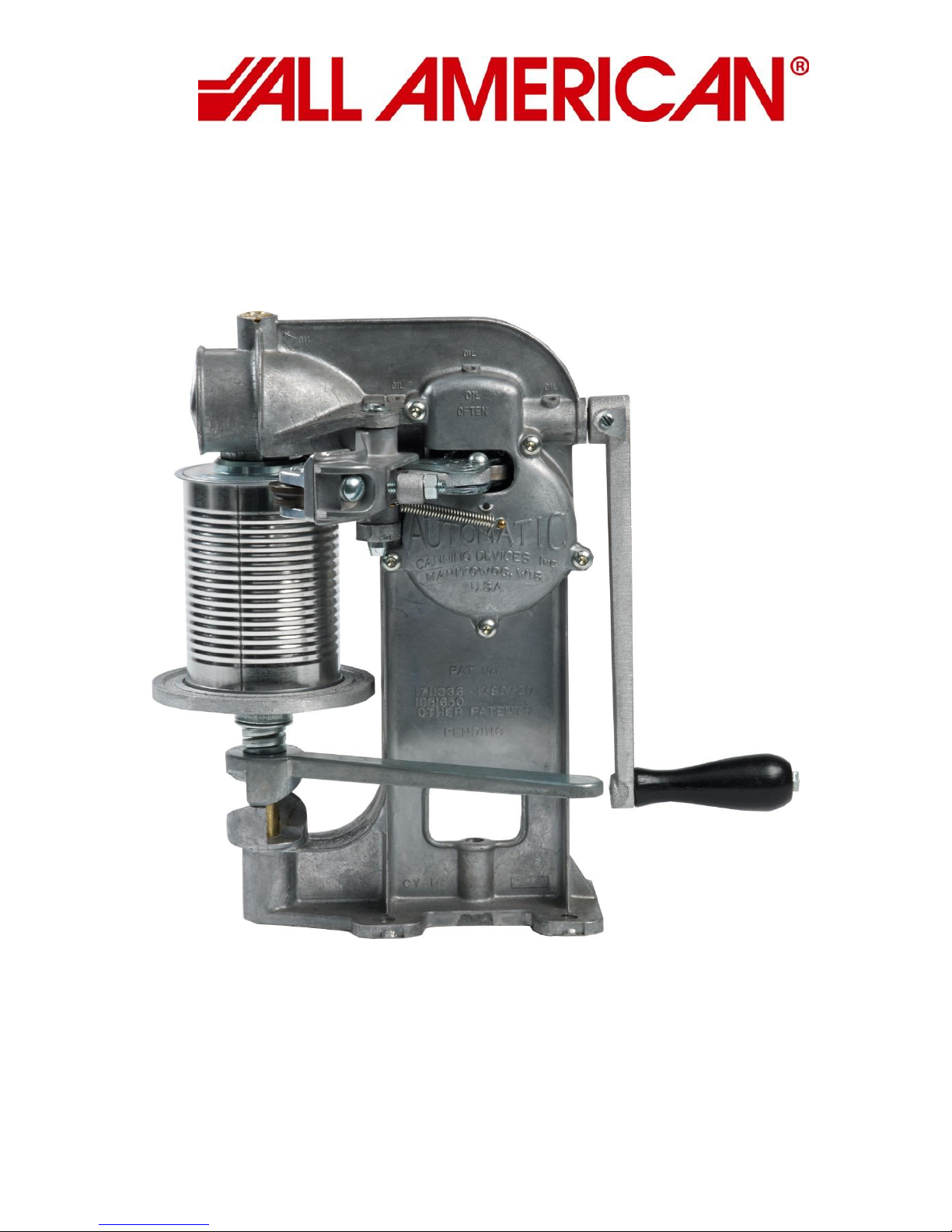
MODEL 225
CAN SEALER
web page: www.allamerican-chefsdesign.com
WISCONSIN ALUMINUM FOUNDRY CO.
1931 SOUTH 14TH STREET
MANITOWOC, WI 54220 USA
920-682-8627 FAX: 920-682-4090
email: customerrelations@wafco.com

Table of Contents
Page 3 - Introduction & Getting Started
Page 4 - Parts Diagram
Page 5 - Maintenance
Page 6 - Adjustments & Seam Gauge
Page 7 - Trouble Shooting
Page 8 - Parts Picture List
Page 9 - Parts List
Page 10 - Warranty Information
Page 11 - Packing List
2

INTRODUCTION
This can sealer was thoroughly inspected and tested at the factory before shipment. Immediately
upon receipt, carefully check the can sealer for damage before using it. Do not operate the can sealer
if it is damaged; call 920-682-8627 for further instruction.
The 225 comes with either the CY-28 No. 2 Chuck or the CY-27 No. 3 chuck and the CY-3 Base Plate.
These are designed and set up to seal a No. 2 or No. 3 can. A sample can was used to set up the
machine and was locked in place during shipping to help protect the machine. Prior to removing the
container, lower and raise the base plate by turning the Can Lifter Handle as far as possible to the left
and then back to the right a few times. Pay attention to the amount of pressure you have to apply to
the Lifter Handle when locking the can into place. It is good to develop a feel for the amount of base
plate pressure required to properly seal a can. Cans with a bigger or smaller diameter will require a
different size Chuck and Base Plate. Height adjustment with spacers is necessary before attempting
to seal other size cans.
GETTING STARTED
1. The sealer can be firmly attached to a table or bar using the four bolt holes (cast into sealer
base) to bolt down the sealer. If that isn’t possible, you can use a C-clamp to attach the sealer
to a bench top.
2. For operation, the seaming lever rivets (CY-22R) should be in the number 2 or the size you are
sealing hole of the cam roller lever (CY-22).
3. Lower the Base Plate (CY-3) by turning the Can Lifter Handle (CY-10) as far as possible to the
left.
4. Place lid on filled can and set can on Base Plate (CY-3).
5. Raise can until it is clamped firmly between the Base Plate and Chuck by turning Can Lifter
Handle (CY-10) as far as possible to the right until handle locks itself against the Frame (CY-1).
The can is now ready to be sealed.
6. Turn the Hand Crank (CY-11) until the first operation roller touches the can. Continue to turn
until the first operation roller pulls away from the can. This hooks the lid to the can. Keep
turning the Hand Crank until the second operation roller touches the can; continue to turn
until the second operation roller pulls away from the can. This finishes the seal. (You will turn
the hand crank a total of 18 times).
7. When both arms are away from the can, pull can lifter handle toward you and remove can.
8. Wipe down the machine frequently to prevent buildup of foreign material.
3
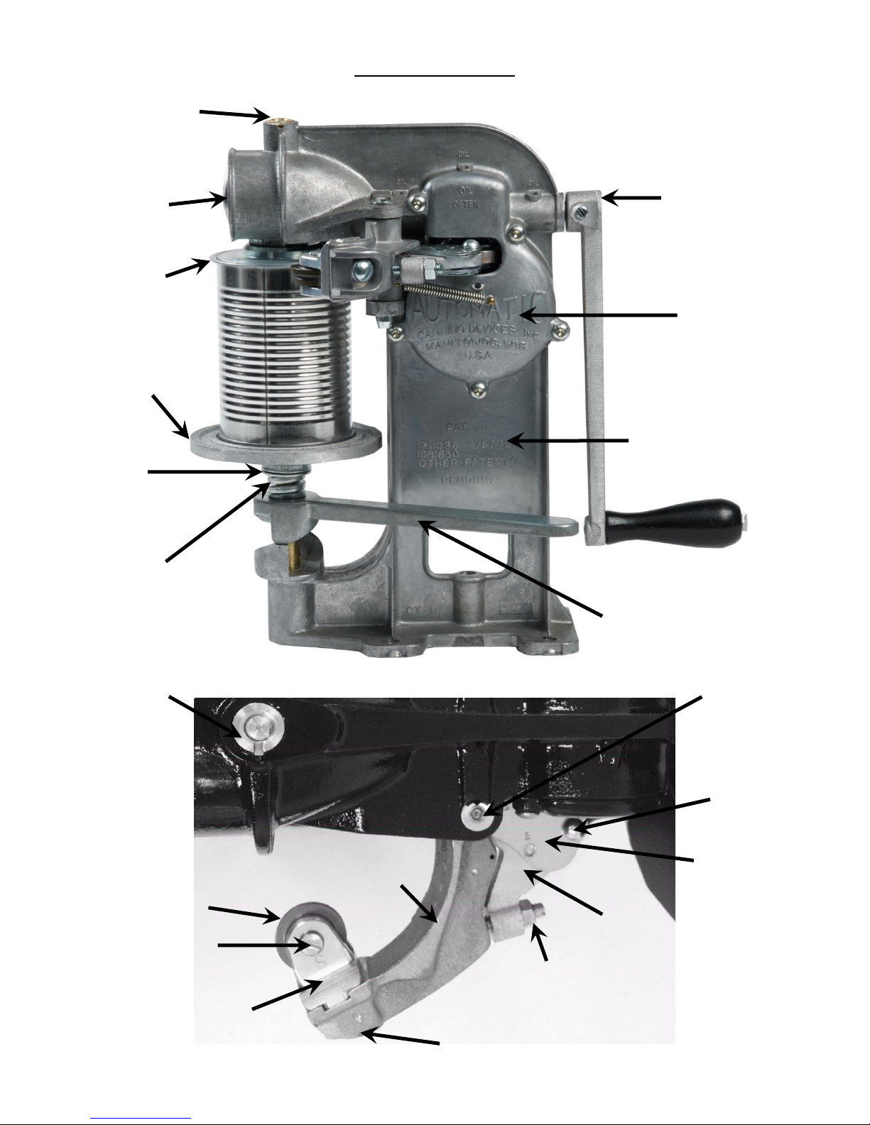
Roller Bearing Lever
CY-9F & CY-9S
Seaming Roller Pin
CY-18F & CY-18S
Seaming Lever
CY-8F& CY-8S
Adjusting Lever
CY-24FS
Cam Roller Lever
CY-22
Operation Roller
CY-14 & CY-15
Lock Screw for Roller Bearing
CY-9LS
Adjusting Screw CY-24AS
and Lock Nut CY-24LN
Crank
Cam Worm Wheel
CY-2
Frame for 225
CY-1
Can Lifter Handle
CY-10
Chuck Holder
CY-19
Front Gear
CY-65
Base Plate
CY-32
Compression
CY-34
Chuck Holder
CY-19
Rivet for Cam Roller
CY-22R
Seaming Lever Pin
CY-17
Base Plate
CY-3
CY-28
PARTS DIAGRAM
Bushing
Complete
Cover
CY-11
No. 2 Chuck
Shaft
Spring
Cover
Bushing
4
 Loading...