


Rhein Tech Laboratories, Inc. Client: Alion Science and Technology
360 Herndon Parkway, Suite 1400 Model: Sensors Communication Module
Herndon, VA 20170 FCC ID: U3M-SCM2007
http://www.rheintech.com
Standard: FCC 15.247
Appendix H: Manual
Please refer to the following pages.
Page 30 of 40

User’s Manual
Sensors Communications Module
21 February 2007
Alion Science and Technology
8100 Corporate Drive
Lanham, MD 20785

This device complies with Part 15 of the FCC Rules.
Operation is subject to the following two conditions:
1. this device may not cause harmful interference, and
2. this device must accept any interference
received, including interference that may cause
undesired operation.
FCC ID: U3M-SCM2007
IMPORTANT NOTE: To comply with FCC RF exposure compliance requirements, the antenna
used for this transmitter must not be co-located or operating in conjunction with any other
antenna or transmitter.
Changes or modifications to this unit not expressly approved by Alion Science and
Technology could void the user’s authority to operate this equipment.
Alion Science and Technology
8100 Corporate Drive
Lanham, MD 20785
1-877-771-6252 (United States)
www.alionscience.com (United States)
© Alion Science and Technology 2006, 2007
21 February 2007
Alion Science and Technology
8100 Corporate Drive
Lanham, MD 20785

Center for Electromagnetic Science
1 Purpose
This document provides operating instructions for users of Alion’s Sensors
Communications Module (SCM).
2 Relevant Documents
SCM Software Requirements Document
Interface Design Specification for the Sensor Communication Module Management Port
2.1 Overview
The SCM is a general purpose device for the collection and dissemination of sensor data.
It is comprised of built in sensors, external sensor interfaces, an RTLS radio, and a
microcontroller. It also has an LCD display, 3 push button switches, 3 LEDs, and a
buzzer that are user configurable. The SCM contains built-in temperature, humidity, and
contact closure sensors, and may optionally contain a GPS receiver. In addition, the
SCM has an external serial port that can be used to interface to other sensors. The serial
port also serves as the management port through which the SCM is placed into Manage
Mode as described by this document.
The SCM operates in either Run Mode or Manage Mode. Run Mode is the normal
mode of operation where the SCM collects data from the various sensors and either stores
it in NVM or transmits it via the RTLS radio. Data can be collected and transmitted at
timed intervals, or as specified by certain events. Events include threshold settings,
button presses, and external inputs.
The Manage Mode allows the user to define how the SCM will function during Run
Mode. Execution of Management Commands allows the user to tailor this behavior to
meet their specific operational needs. Manage Mode also provides for a Test
Command that causes the SCM to execute a built-in-test (BIT). Likewise, Management
Commands provide a means for the user to retrieve SCM configuration settings as well
as any data contained in nonvolatile memory (NVM). NVM data may hold data logged
from prior SCM utilization, or it may contain BIT results.
SCM Configuration Application Program (SCMCAP) is an automation of Management
Commands with built-in error checking. SCMCAP allows users to configure the SCM
for specific applications and uses.
8100 Corporate Drive – Hyattsville, Maryland 20785-2231
Phone 301-918-1084 Fax 301-918-1544
Page 3 of 16

Center for Electromagnetic Science
3 SCMCAP Instructions
SCMCAP operates as a stand-alone Microsoft Windows PC application. Insert the SCM
software disk into the PC CDROM drive. It will automatically install. Follow the onscreen instructions during installation.
Connect an SCM to the PC’s serial port using the cable provided in the kit. Start the
SCMCAP program.
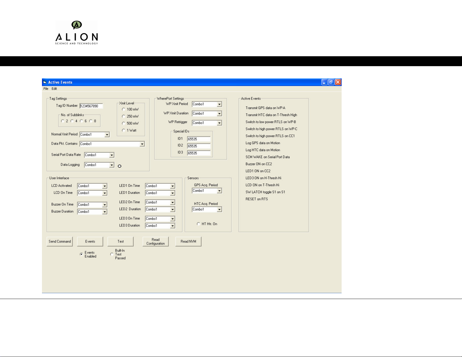
When launched, the SCMCAP Main Form will appear as shown in Figure 1. It contains
the following provisions:
a) Writing new configuration settings to the SCM
b) Setting Tag parameters
c) Defining user interface characteristics
d) Configuring the built-in sensors
e) Setting event-driven Actions
f) Reading the current configuration settings from an SCM
g) Retrieving SCM Nonvolatile memory
h) Testing the SCM
i) Placing the SCM in Run Mode
Placing the mouse pointer over a button or title will cause a definition of that field’s
function to be displayed.
8100 Corporate Drive – Hyattsville, Maryland 20785-2231
Phone 301-918-1084 Fax 301-918-1544
Page 4 of 16
Center for Electromagnetic Science
Cyclical
Figure 1: Main Form
8100 Corporate Drive – Hyattsville, Maryland 20785-2231
Phone 301-918-1084 Fax 301-918-1544
Page 5 of 16
EXAMPLE

Center for Electromagnetic Science
3.1 Writing New Configuration Settings to the SCM
1 After setting SCM configuration parameters, click on the Send button to write the
settings to the SCM.
2 SCMCAP settings can be saved using the pull down menu File-Save. The user will
be prompted to save the settings before writing them to the SCM.
3 SCMCAP will perform an error check on the configuration data set. The user is
notified if errors are found and what they are. The write is terminated without
execution until all errors have been corrected.
3.2 Setting Tag Parameters
SCMCAP provides a means to set the following tag parameters:
a) ID Number
b) Transmit Power Level
c) Number of Subblinks
d) Normal Transmit Period
e) Serial Port Data Rate
f) Data to be Logged
g) Time and Date
Requirements for each of these parameters are given in the paragraphs below.
3.2.1 Tag Identification Number
1 SCMCAP will provide a way to assign an ID number to the SCM using a free-form
data entry field, such as a Text Box. The Tag Identification Number is a numeric
field of 1 to 10 digits. Only the numbers 0-9 are acceptable digit values.
3.2.2 RTLS Power Level
1 Tthe RTLS transmit power level can be set to one of three possible settings using an
Option Button or Check Box for each. Only one entry may be set
3.2.3 Number of Subblinks per transmission
1 Set the number of subblinks transmitted per RTLS transmission using this Option
Button or Check Box. Only one entry may be set
8100 Corporate Drive – Hyattsville, Maryland 20785-2231
Phone 301-918-1084 Fax 301-918-1544
Page 6 of 16

Center for Electromagnetic Science
3.2.4 Normal Transmit period
Set the RTLS transmit period in seconds. The list contains settings for:
a) 0, 5, 10, 15, 20, 30, 45 seconds
b) 1, 2, 5, 10, 15, 30, 45 minutes
c) 1 – 24 hours (1 hour increments)
3.2.5 Data Packet Contents
Specify what data is transmitted in RTLS packets. SCMCAP allows entry selection from
a finite list of choices. The list will contain settings for:
a) Tag Settings
b) GPS data only
c) HTC data only
d) Serial Port buffer data only
e) Both GPS and HTC data
f) Both GPS and Serial Port buffer data
3.2.6 Serial Port Data Rate
1 Sets the Serial Port data rate. Serial port is always 8 data bits, no parity, 1 stop bit.
Settings are:
a) Disable port for data
b) 2400
c) 9600
d) 19200
e) 57600
2 The user is prompted if, on writing to the SCM, it determines that the current data
rate is different than that entered here. The user is given the option to proceed or to
abort the Send Command action.
3.2.7 Data Logging
1 Define data to be logged to nonvolatile memory (NVM). The settings are:
a) Disable data logging
b) GPS only
c) GPS and Time
8100 Corporate Drive – Hyattsville, Maryland 20785-2231
Phone 301-918-1084 Fax 301-918-1544
Page 7 of 16

Center for Electromagnetic Science
d) Temperature Only
e) Temperature and Time
f) Humidity Only
g) Humidity and Time
h) GPS, Temperature, Time
i) GPS, Humidity, Time
j) GPS, Temperature, Humidity, Time
k) Serial Port and Time
l) GPS, Serial Port, Time
2 Data logging will stop once the buffer is filled unless the “Cyclical” button is
selected. If the “Cyclical” button is selected the data will write over the earliest entry
once the buffer is full.
3 Unless Disable data logging is selected, the user is prompted that any existing data
in NVM may be lost. The user is given the option to proceed or abort the Send
Command action.
3.2.8 Time and Date
1. Set the time and date used by the SCM. SCMCAP will check the time against the
resident computer time and date, and prompt the user if they are different by more
than one (1) minute.
3.2.9 LCD Activate On Measurement
Sets which measurement turns on the LCD and displays the measured data. Occurs for
both timed and event driven measurements. S3 can always be used to activate the LCD
Menu. Available choices are:
a) Off
b) GPS
c) HTC
d) Serial Port
3.2.10 LCD On Time
Sets the time in seconds that the LCD display remains on before turning off. Applies to
all conditions that activate the LCD, except S3 activation. SCMCAP will allow entry
selection from a finite list of choices. Available choices are:
a) Disabled
b) 10, 15, 20, 30, 60,120
c) Indefinitely
8100 Corporate Drive – Hyattsville, Maryland 20785-2231
Phone 301-918-1084 Fax 301-918-1544
Page 8 of 16

Center for Electromagnetic Science
3.2.11 LED Number 1 Blink Rate
Sets the time in milliseconds that LED1 remains on per 5 seconds. Applies to all events
that specify LED1. Available choices are:
a) Off
b) 200 mS
c) 500 mS
d) 700 mS
e) 1 Second
f) 2 Second
3.2.12 LED Number 1 Blink Duration
Specifies the time in minutes that LED1 will blink at the specified blink rate. Applies to
all events that specify LED1. Available choices are:
a) Disabled
b) 1,2, 5, 10, 20, 30, 60, 120, 240
c) Indefinitely
3.2.13 LED Number 2 Blink Rate
Sets the time in milliseconds that LED2 remains on per 5 seconds. Applies to all events
that specify LED2. Available choices are:
a) Off
b) 200 mS
c) 500 mS
d) 700 mS
e) 1 Second
f) 2 Second
3.2.14 LED Number 2 Blink Duration
Specifies the time in minutes that LED2 will blink at the specified blink rate. Applies to
all events that specify LED2. Available choices are:
a) Disabled
b) 1, 2, 5, 10, 20, 30, 60, 120, 240
c) Indefinitely
8100 Corporate Drive – Hyattsville, Maryland 20785-2231
Phone 301-918-1084 Fax 301-918-1544
Page 9 of 16

Center for Electromagnetic Science
3.2.15 LED Number 3 Blink Rate
Sets the time in milliseconds that LED3 remains on per 5 seconds. Applies to all events
that specify LED3. Available choices are:
a) Off
b) 200 mS
c) 500 mS
d) 700 mS
e) 1 Second
f) 2 Second
3.2.16 LED Number 3 Blink Duration
Specifies the time in minutes that LED3 will blink at the specified blink rate. Applies to
all events that specify LED3. Available choices are:
a) Disabled
b) 2, 5, 10, 20, 30, 60, 120, 240
c) Indefinitely
3.2.17 Buzzer On Time
Specifies the time in seconds that the Buzzer remains on. Applies to all events that
specify BUZZER_ON. Available choices are:
1, 2, 5, 10, 20, 30 seconds.
When Buzzer On Time exceeds the current settings for Buzzer Period and Buzzer
Duration, SCMCAP will automatically adjust Buzzer Period and Buzzer Duration to the
lowest possible valid settings. The user is notified of the changes.
3.2.18 Buzzer Period
Specifies the time interval in seconds between Buzzer activations of Buzzer On Time.
Applies to all events that specify BUZZER_ON. Available choices are:
2, 5, 10, 20, 30, 60, 120, 240 seconds.
SCMCAP will check that Buzzer Period is greater than or equal to Buzzer On Time.
Those settings that are not will be insensitive and unavailable to the user. Alternatively,
the user will be prompted of the error and the last entry ignored.
8100 Corporate Drive – Hyattsville, Maryland 20785-2231
Phone 301-918-1084 Fax 301-918-1544
Page 10 of 16

Center for Electromagnetic Science
3.2.19 Buzzer Duration
Specifies the time in minutes over which the Buzzer cycle will occur. Applies to all
events that specify BUZZER_ON. Available choices are:
a) Disabled
b) 1, 2, 5, 10, 20, 30, 60,120,240
c) Indefinite
SCMCAP swill check that Buzzer Duration is greater than or equal to Buzzer Period.
Those settings that are not will be insensitive and unavailable to the user. Alternatively,
the user will be prompted of the error and the last entry ignored.
3.3 Configuring the Built-In Sensors
3.3.1 GPS Acquisition Period
Set the time between GPS attempts to acquire a location fix. SCMCAP will allow entry
selection from a finite list of choices. The list will contain settings for:
a) Disabled
b) 2, 5, 10, 20, 30 seconds
c) 1, 5, 10, 15, 20, 30, 45 minutes
d) 1, 2, 4, 6, 8, 12, 24 hours
3.3.2 Humidity and Temperature Acquisition Period -HTAcPer
Sets the time between measurements of temperature, humidity, and the states of the
external contact closures. SCMCAP will allow entry selection from a finite list of
choices. The list will contain settings for:
a) Disabled
b) 1, 2, 5, 10, 20, 30 seconds
c) 1, 5, 10, 15, 20, 30, 45 minutes
d) 1, 2, 4, 6, 8, 12, 24 hours
3.3.3 High Temperature Threshold – THi
Defines the high temperature threshold in degrees Fahrenheit that is used to trigger events
as defined by the Event command.
8100 Corporate Drive – Hyattsville, Maryland 20785-2231
Phone 301-918-1084 Fax 301-918-1544
Page 11 of 16

Center for Electromagnetic Science
The field will only accept numbers 0-9, up to 3 digits and the sign symbols + and -. No
sign symbol is interpreted as positive. The allowed range of valid entries will be limited
to the range of -41 to +254
The user will be prompted when errors are made entering data.
3.3.4 Low Temperature Threshold – TLo
Defines the low temperature threshold in degrees Fahrenheit that is used to trigger events
as defined by the Event command.
The field will only accept numbers 0-9, up to 3 digits and the sign symbols + and -. No
sign symbol is interpreted as positive. The allowed range of valid entries will be limited
to the range of -40 to +253
The user will be prompted when errors are made entering data.
3.3.5 High Humidity Threshold – HHi
Defines the high relative humidity threshold as a percent that is used to trigger events as
defined by the Event command.
The field will only accept numbers 0-9, up to 2 digits. The allowed range of valid entries
will be limited to the range of 1 to 100
The user will be prompted when errors are made entering data.
3.3.6 Low Humidity Threshold – HHi
Defines the high relative humidity threshold as a percent that is used to trigger events
as defined by the Event command.
The field will only accept numbers 0-9, up to 2 digits. The allowed range of valid
entries will be limited to the range of 1 to 100
The user will be prompted when errors are made entering data.
8100 Corporate Drive – Hyattsville, Maryland 20785-2231
Phone 301-918-1084 Fax 301-918-1544
Page 12 of 16

Center for Electromagnetic Science
3.4 Setting Event-Driven Actions
3.4.1 Summary Event List
SCMCAP will display on the Main Form a summary list of all event-driven actions
currently set. The list will include the Action and the event that causes it.
The summary list will be updated immediately to reflect changes made by the user.
3.4.2 Events Command Button
The main form of SCMCAP will contain an Events Command Button that when clicked
on by the user causes an Actions-Events Entry Table to open as a separate form in its
own window.
The Actions-Events Entry Table Form will contain all possible actions, and the events
that may cause such actions, in a manner that allows the user to quickly set or clear them
as desired.
SCMCAP will perform the necessary checking to ensure that mutual exclusivity is
retained correctly, and it will automatically make changes to the Form settings as the user
selects or deselects items accordingly to maintain exclusivity rules.
8100 Corporate Drive – Hyattsville, Maryland 20785-2231
Phone 301-918-1084 Fax 301-918-1544
Page 13 of 16

Center for Electromagnetic Science
Figure 2: Actions - Events Form
Example
8100 Corporate Drive – Hyattsville, Maryland 20785-2231
Phone 301-918-1084 Fax 301-918-1544
Page 14 of 16

Center for Electromagnetic Science
3.5 Reading Configuration Settings from the SCM
The Main Form of the SCMCAP will include a Command Button that retrieves the
current SCM configuration settings.
SCMCAP will populate the Main Form with the retrieved data.
Before doing so, SCMCAP will prompt the user that current settings will be lost and offer
to the user to save them before execution of the data retrieval.
3.6 Reading Nonvolatile Memory
The Main Form of SCMCAP will include a Command Button that retrieves the contents
of Nonvolatile Memory (NVM).
SCMCAP will prompt the user for a file name and location to save the retrieved data.
SCMCAP will then saved the data to the file specified as a simple, space-delimited text
file.
3.7 Test the SCM
The Main Form of SCMCAP will include a Command Button that causes the SCM to
execute a Built-In Test (BIT).
SCMCAP will warn the user that BIT will erase any data held in NVM and offer the user
the option to abort BIT.
SCMCAP will display an indicator that BIT is in progress, and for the user to wait until
BIT is complete before proceeding.
SCMCAP will inform the user when the test is complete, indicating pass or fail, and
pointing out that the results are now available in NVM for retrieval.
SCMCAP will sense that the BIT is complete, and whether it passed or failed. SCMCAP
will indicate on the Main Form whether BIT passed or failed by setting and clearing the
appropriate Built-In Test Status Radio Button.
3.7.1 Placing the SCM in Run Mode
SCMCAP will provide a Command Button that, when clicked on by the user, places the
SCM in normal Run Mode.
8100 Corporate Drive – Hyattsville, Maryland 20785-2231
Phone 301-918-1084 Fax 301-918-1544
Page 15 of 16

Center for Electromagnetic Science
The user will be prompted that they are about to exit Manage Mode, and given the
option to abort the command.
8100 Corporate Drive – Hyattsville, Maryland 20785-2231
Phone 301-918-1084 Fax 301-918-1544
Page 16 of 16
 Loading...