


ALINKET Alinket
Version 2.0
September 20, 2016
wireless controller
ALXC12B User Manual
Alinket Technology Corp. www.alinket.com Proprietary & Confidential Information 1
All Rights Reserved. E-mail: sales@alinket.com

ALXC12B User Manual
Copyright
©2015-2016 Alinket Technologies Corporation. All rights reserved.
This document is the property of Alinket Electronic Technologies Corp and is delivered
on the express condition that it not be disclosed, reproduced in whole or in part, or used
for manufacture for anyone other than Alinket Technologies Corp without its written
consent, and that no right is granted to disclose or so use any information contained in
said document. This restriction does not limit the right to use information obtained from
other sources.
Trademarks
ALXC12B is a registered trademark of Alinket Electronic Technologies Corp. Alinket is a
registered trademark of Alinket Technologies Corp. Other products and company names
mentioned here in may be the trademarks of their respective owners.
Alinket Technology Corp. www.alinket.com Proprietary & Confidential Information 2
All Rights Reserved. E-mail: sales@alinket.com

Revision History
Date(M/D/Y)
Revision Content
Revision By
Version
5/18/2016
Initialization Version
Shi Qi
1.0
9/20/2016
Change to New Template
Nigel Ding
2.0
ALXC12B User Manual
Alinket Technology Corp. www.alinket.com Proprietary & Confidential Information 3
All Rights Reserved. E-mail: sales@alinket.com

ALXC12B User Manual
List of Contents
1. INTRODUCTION ................................................................................................................................. 9
1.1 OVERVIEW ......................................................................................................................................... 9
1.2 HARDWARE ARCHITECTURE ................................................................................................................. 10
1.3 INTERFACE AND PERIPHERALS .............................................................................................................. 10
1.4 PHYSICAL DIMENSIONS ....................................................................................................................... 11
1.4.1 Mechanical Size ........................................................................................................................ 11
1.4.2 PCB Footprint ........................................................................................................................... 11
1.5 PIN ASSIGNMENT ............................................................................................................................. 12
1.6 PIN DESCRIPTION .............................................................................................................................. 12
2. HARDWARE DESIGN GUIDE ............................................................................................................. 14
2.1 SMALLEST SYSTEM ............................................................................................................................. 14
2.2 TYPICAL APPLICATION......................................................................................................................... 14
2.3 POWER ............................................................................................................................................ 15
2.4 UART INTERFACE .............................................................................................................................. 16
2.5 SPI INTERFACE .................................................................................................................................. 16
2.6 I2C INTERFACE .................................................................................................................................. 16
2.7 ADC & GPIO ................................................................................................................................... 17
2.8 NRST .............................................................................................................................................. 17
3. SOFTWARE DESIGN GUIDE .............................................................................................................. 18
3.1 UART TRANSPARENT MODE ............................................................................................................... 18
3.2 ACM MODE .................................................................................................................................... 18
4. TEST & DEBUG MANUAL ................................................................................................................. .19
4.1 PREPARATION .................................................................................................................................... 19
4.1.1 Tools .......................................................................................................................................... 19
4.1.2 Evaluation Kit ...........................................................................................................................20
4.1.3 Set Up ....................................................................................................................................... 22
4.2 PROCESS INTRODUCTION .................................................................................................................... 24
4.2.1 Wi-Fi Transparent Mode .......................................................................................................... 24
4.2.2 ACM Mode for Wi-Fi ................................................................................................................ 27
4.2.3 ACM Mode for BT ..................................................................................................................... 32
4.2.4 ACM Mode for BLE ................................................................................................................... 37
5. WORK CONDITION .......................................................................................................................... 38
5.1 RANGE OF OPERATION ....................................................................................................................... 38
5.2 RECOMMENDED OPERATION RANGE .................................................................................................... 38
6. MANUFACTURING ........................................................................................................................... 39
Alinket Technology Corp. www.alinket.com Proprietary & Confidential Information 4
All Rights Reserved. E-mail: sales@alinket.com

ALXC12B User Manual
6.1 RECOMMENDED REFLOW PROFILE ....................................................................................................... 39
6.2 ROHS DECLARATION ......................................................................................................................... 39
7. ORDERING INFORMATION ............................................................................................................... 40
8. TECHNICAL SUPPORT ...................................................................................................................... 40
9. REFERENCE ..................................................................................................................................... 40
APPENDIX: ACRONYMS AND ABBREVIATIONS ....................................................................................... 41
Alinket Technology Corp. www.alinket.com Proprietary & Confidential Information 5
All Rights Reserved. E-mail: sales@alinket.com

ALXC12B User Manual
List of Figures
Figure 1 Top View ................................................................................................................... 9
Figure 2 Block Diagram ......................................................................................................... 10
Figure 3 Pad Dimension (Top View) ...................................................................................... 11
Figure 4 Ball Maps ................................................................................................................ 12
Figure 5 Smallest System ...................................................................................................... 14
Figure 6 Typical Application .................................................................................................. 14
Figure 7 Power Circuit .......................................................................................................... 15
Figure 8 VDDIO Circuit .......................................................................................................... 15
Figure 9 PUART Circuit .......................................................................................................... 16
Figure 10 SPI Circuit .............................................................................................................. 16
Figure 11 I2C Circuit ............................................................................................................. 16
Figure 12 NRST ..................................................................................................................... 17
Figure 13 Antenna Area ........................................................................................................ 18
Figure 14 ALXC12X EVK ......................................................................................................... 21
Figure 15 Without HW Flow Control .................................................................................... 22
Figure 16 With HW Flow Control .......................................................................................... 22
Figure 17 Connection Diagram – Without HW Flow Control ................................................ 23
Figure 18 Connection Diagram – With HW Flow Control ...................................................... 23
Figure 19 Connection Map – Normal Case ........................................................................... 24
Figure 20 Connection Map – Roaming ................................................................................. 24
Figure 21 Connection Map - EAP .......................................................................................... 24
Figure 22 Set up a Server ...................................................................................................... 25
Figure 23 Network Configuration – Flashlink ........................................................................ 26
Figure 24 TCP Connected ..................................................................................................... 27
Figure 25 ACMTH Function Blocks ........................................................................................ 28
Figure 26 Add Serial Port in ACMTH ..................................................................................... 29
Figure 27 ACM Operation ..................................................................................................... 29
Figure 28 Roaming Setup ...................................................................................................... 30
Figure 29 Get AP Information ............................................................................................... 30
Figure 30 Set Roaming Parameters ....................................................................................... 31
Figure 31 EAP Configuration ................................................................................................. 32
Figure 32 Wi-Fi Join for EAP .................................................................................................. 32
Figure 33 Wi-Fi On ................................................................................................................ 33
Figure 34 BT On .................................................................................................................... 33
Figure 35 Ready for Pairing ................................................................................................... 34
Figure 36 Pairing Successful.................................................................................................. 34
Figure 37 Connecting through RFCOMM .............................................................................. 35
Figure 38 Connected Status Indication ................................................................................. 35
Figure 39 Master & Slave Test Connection ........................................................................... 36
Figure 40 Port Configuration by ACMTH ............................................................................... 36
Figure 41 Setup Connection between Master & Slave ......................................................... 37
Alinket Technology Corp. www.alinket.com Proprietary & Confidential Information 6
All Rights Reserved. E-mail: sales@alinket.com

ALXC12B User Manual
Figure 42 Connection Successful Indication ......................................................................... 37
Figure 43 BLE On .................................................................................................................. 38
Figure 44 BLE Operation ....................................................................................................... 38
Figure 45 Reflow Profile ........................................................................................................ 40
Alinket Technology Corp. www.alinket.com Proprietary & Confidential Information 7
All Rights Reserved. E-mail: sales@alinket.com

ALXC12B User Manual
List of Tables
Table 1 Product Family ............................................................................................................ 9
Table 2 MCU and Interfaces .................................................................................................. 10
Table 3 Mechanical Dimensions ........................................................................................... 11
Table 4 Pin Descriptions ........................................................................................................ 12
Table 5 GPIO List ................................................................................................................... 17
Table 6 Hardware Tools ......................................................................................................... 20
Table 7 Software Tools .......................................................................................................... 20
Table 8 USB – UART Convertor PIN ....................................................................................... 22
Table 9 Roaming Parameters ................................................................................................ 31
Table 10 Range of Operation – General Specification ........................................................... 39
Table 11 Recommended Voltage .......................................................................................... 39
Table 12 Recommended Temperature and Humidity ........................................................... 39
Table 13 Order Information .................................................................................................. 41
Alinket Technology Corp. www.alinket.com Proprietary & Confidential Information 8
All Rights Reserved. E-mail: sales@alinket.com

ALXC12B User Manual
1. Introduction
1.1 Overview
Alinket ALXC12B , which has Wi-Fi 802.11b/g/n and Bluetooth 4.1 functionalities, is a portfolio of
low-powered, self-contained, embedded wireless module solutions that address the connectivity
demands of machine to machine applications.
ALXC12B supports a U.FL connector which provides the flexibility for customer to pick up
its own proper external antenna.
Table 1 Product
ALXC12B Wi-Fi 2.4GHz + BT 4.1 IoT Controller, External Antenna, Support U.FL
Figure 1 Top View
Alinket Technology Corp. www.alinket.com Proprietary & Confidential Information 9
All Rights Reserved. E-mail: sales@alinket.com

ALXC12B User Manual
Model
Wi-Fi Technology
IEEE 802.11 b/g/n, Wi-Fi 2.4G
Frequency Band – Wi-Fi
2,400MHz ~ 2,500MHz
Bluetooth Technology
Bluetooth 4.1 (BR/EDR/LE)
Frequency Band – BT
2,402 MHz ~ 2,480 MHz
MCU
Core
ARM® Cortex®- M4 @100MHz
RAM
128KB
ROM
512KB
Flash (On-Board)
1MB
Host Interfaces
UART x 1
Up to 6.25Mbps
SPI x 1
50MHz, multiplexing with USB
Peripherals
I2C x 1
Support 100KHz, 400KHz & 1MHz
ADC x 6
12bit, 16 channel, multiplexing with GPIO
GPIO x 16
Max., multiplexing with interface & peripherals
1.2 Hardware Architecture
ALXC12B integrates an ARM® 32-bit Cortex®-M4 micro-controller, a Wi-Fi 2.4GHz & Bluetooth
4.1 SoC, an On-Board SPI Flash into the small factor module.
Figure 2 Block Diagram
1.3 Interface and Peripherals
The controller family includes various different host interfaces to communicate with Host CPU.
Below table lists the basic descriptions of the MCU, Wi-Fi SoC and the interfaces.
Table 2 MCU and Interfaces
ALXC12B
Note: SPI, I2C interfaces are for customized projects only, not for standard product, please contact
your local Alinket sales office or distributors for more information.
Alinket Technology Corp. www.alinket.com Proprietary & Confidential Information 10
All Rights Reserved. E-mail: sales@alinket.com

1.4 Physical Dimensions
Parameter
Typical
Units
Dimensions (L x W x H)
32 x 16 x 3.1
mm
Dimensions tolerances (L x W x H)
±0.2
mm
1.4.1 Mechanical Size
Table 3 Mechanical Dimensions
1.4.2 PCB Footprint
ALXC12B User Manual
Alinket Technology Corp. www.alinket.com Proprietary & Confidential Information 11
All Rights Reserved. E-mail: sales@alinket.com
Figure 3 Pad Dimension (Top View)

1.5 PIN Assignment
Pins
Type
Name
Main function
Alternate functions
PIN connection
(when not using )
1
NC
2
I/O
GPIO1
GPIO
floating
3
4
I/O
SPI1_MOSI
GPIO
floating
ALXC12B PIN ball maps are described as follows.
ALXC12B User Manual
Figure 4 Ball Maps
1.6 PIN Description
Table 4 Pin Descriptions
Alinket Technology Corp. www.alinket.com Proprietary & Confidential Information 12
All Rights Reserved. E-mail: sales@alinket.com

ALXC12B User Manual
5
I/O
SPI1_NSS
GPIO/ADC
floating
6
I/O
SPI1_SCK
GPIO
floating
7
I/O
SPI1_MISO
GPIO
floating
8
I/O
USART_TX
GPIO/ADC
floating
9
I/O
GPIO2
ADC
floating
10 V VBAT
3.3V
11
NC
12
I/O
USART_RX
GPIO/ADC
floating
13 I NRST
Active-low reset input
PULL UP
14 I MICRO_WKUP
Wake up
floating
15
NC
16
NC
17
I/O
I2C_SCL
GPIO
floating
18
I/O
I2C_SDA
GPIO
floating
19
I/O
I2C_SMBA
GPIO
floating
20 S GND
21 S GND
22
I/O
JTAG_Tdo
GPIO
floating
23
I/O
JTAG_TDI/SPICont
GPIO
floating
24
JTAG_TRST
floating
25
I/O
JTAG_TCK/SWCLK
JTCK-SWCLK
floating
26
I/O
JTAG_TMS/SWDIO
JTCK-SWDIO
floating
27
NC
28
NC
29
NC
30
NC
31
I/O
GPIO3
GPIO
floating
32
NC
33
NC
34
NC
35
NC
36
I/O
GPIO4
ADC
floating
37
I/O
GPIO5
ADC
floating
38
NC
39 V VDD_3V3
3.3V
40 V VDD_3V3
3.3V
41
ANT
ANT_PAD
RF OUTPUT
floating
Alinket Technology Corp. www.alinket.com Proprietary & Confidential Information 13
All Rights Reserved. E-mail: sales@alinket.com

ALXC12B User Manual
2. Hardware Design Guide
2.1 Smallest System
The ALXC12B embedded a Cortex-M4 MCU, Wi-Fi + BT combo SoC, Flash memory and an on-
board or external antenna, when it’s power on and pulled up the 10K Ohm connected to NRST
(PIN13), it can start to work, shown as below Figure.
Figure 5 Smallest System
2.2 Typical Application
ALXC12B provides multiple host interface and peripheral interfaces such as UART, SPI, I2C and
GPIO. A typical application is ALXC12B to be connected by a customer host through UART or SPI
interface and GPIO for status or application controls. Then the ALXC12B device can connect and
communicate with an AP/router or Bluetooth devices and transmit or receive data with a server.
Figure 6 Typical Application
Alinket Technology Corp. www.alinket.com Proprietary & Confidential Information 14
All Rights Reserved. E-mail: sales@alinket.com

ALXC12B User Manual
2.3 Power
ALXC12B module default power is 3.3V, reference power circuit shown below. Please note that
the power ripple should be controlled within 50mV.
Figure 7 Power Circuit
The power access to the VDDIO pin needs a filtering circuit shown below.
Figure 8 VDDIO Circuit
Alinket Technology Corp. www.alinket.com Proprietary & Confidential Information 15
All Rights Reserved. E-mail: sales@alinket.com

ALXC12B User Manual
2.4 UART Interface
ALXC12B has one standard UART with a maximum data rate up to 6 Mbps. The default baud rate
is 115,200 which can be configured by Alinket ACM (Alinket Control Messages) command.
The PINs for UART interface is: UART_Tx/PIN 8, UART_Rx/PIN 12, its reference circuit to a host
MCU is shown below.
Figure 9 PUART Circuit
2.5 SPI Interface
The ALXC12B has one independent SPI interface. It can be either a master or a slave. It
can communicate at up to minimum 25 Mbps to 50MHz.
The PINs for SPI interface is: SPI_MOSI/PIN 4, SPI_NSS/PIN 5, SPI_CLK/PIN 6, SPI_MISO/PIN 7, SPI
reference circuit to MCU is shown below.
Figure 10 SPI Circuit
2.6 I2C Interface
I2C bus interfaces can operate in both master and slave modes. It can support the standard (up to
100 kHz) and fast (up to 400 kHz) modes. Its frequency can be increased up to 1 MHz.
The PINs for I2C interface is I2C_SDA/PIN 5, I2C_CSL/PIN 6. Reference circuit is shown below.
Figure 11 I2C Circuit
Alinket Technology Corp. www.alinket.com Proprietary & Confidential Information 16
All Rights Reserved. E-mail: sales@alinket.com

ALXC12B User Manual
No.
Pin#
Main function
Alternate functions
1
2
GPIO1
GPIO
2
4
SPI1_MOSI
GPIO
3
5
SPI1_NSS
GPIO/ADC
4
6
SPI_SLK
GPIO
5
7
SPI_MISO
GPIO
6
8
USART_TX
GPIO/ADC
7
9
GPIO2
ADC
8
12
USART_RX
GPIO/ADC
9
17
I2C_SCL
GPIO
10
18
I2C_SDA
GPIO
11
19
I2C_SMBA
GPIO
12
22
JTAG_Tdo
GPIO
13
23
JTAG_TDI/SPICont
GPIO
14
31
GPIO3
GPIO
15
36
GPIO4
ADC
16
37
GPIO5
ADC
2.7 ADC & GPIO
ALXC12B has 6 ADC and 16 GPIO interfaces. All of GPIO ports support programmable pull-up and
pull-down resistors and can be directly connected. The ADC and GPIO are multiplexed & list
below. Table 5 GPIO List
2.8 NRST
Under some circumstance, ALXC12B need to be reset to recovery its system. An external signal
needs to be provide to the NRST of ALXC12B. NRST (PIN 13) reference circuit is shown below.
Figure 12 NRST
Alinket Technology Corp. www.alinket.com Proprietary & Confidential Information 17
All Rights Reserved. E-mail: sales@alinket.com

ALXC12X User Manual
3. Software Design Guide
ALXC12B support two work modes: UART Transparent Mode and ACM Mode.
3.1 UART Transparent Mode
ALXC12B supports serial interface transparent transmission mode when Bluetooth is not used.
The benefits of this mode are a plug and play serial data port, and reduced user complexity. In
this mode, the user should only configure the necessary parameters. After power on, the module
can automatically connect to the default master.
If Bluetooth is used, only ACM mode is supported.
3.2 ACM Mode
ACM (Alinket Controller Message) is a message system and protocol for the communications
between customer host MCU and Alinket IoT controllers. It is developed by Alinket itself and is
applicable to all Alinket controllers.
ACM system works with the host control interfaces between customer host MCU and Alinket
controllers. The messages include host control commands, controller command response, and alarm
events from Alinket controller as well.
Detailed message definition, the implementation of massage Flow Control and Power Save functions
can be found in documents of Alinket Controller Message Specification, Alinket Host Control
Interface Guide (* Please contact your local Alinket sales office or distributors to get the related
documents).
Alinket Technology Corp. www.alinket.com Proprietary & Confidential Information 18
All Rights Reserved. E-mail: sales@alinket.com

ALXC12B User Manual
No.
Tools
Note
Quantity
1
PC
Used for send/receive commands, connect
the module, OS: Win 8.0 or above
1
2
Perform Wi-Fi & Bluetooth functions
2
3
Dupont Line
1
4
FT232 USB to UART Board
USB-to-Serial converter (TTL interface)
2 5 AP
Wi-Fi AP (Access Point)
2 6 AC
Wi-Fi AC (AP Controller)
1
No.
Tools
Note
Quantity 1 ACMTH
Alinket Controller Message Test Host
/ 2 UartAssist
UART send/receive commands tool
/ 3 SocketRunner
Simulator a Server on PC
/ 4 Flashlink
Network configuration (AP and Server)
/
5
RFCOMM
Alinket RFCOMM Test Host, it can send and
receive data between BT module and BT of PC
/
4. Test & Debug Manual
4.1 Preparation
4.1.1 Tools
4.1.1.1 Hardware Tools
Hardware tools include ALXC12B module, EVK, PC, USB-to-Serial converter (TTL interface), Wi-Fi
AP, Wi-Fi AC.
Table 6 Hardware Tools
ALXC12B EVK
Connect from FT232 USB – UART Board
to ALXC12BEVK
4.1.1.2 Software Tools
Software tools include PC (Win 8.0 or above), Serial Debugger Tool (UARTAssist), ACMTH, Alinket
SocketRunner, Flashlink & RFCOMM.
Table 7 Software Tools
Alinket Technology Corp. www.alinket.com Proprietary & Confidential Information 19
All Rights Reserved. E-mail: sales@alinket.com

ALXC12B User Manual
4.1.2 Evaluation Kit
Alinket provides the evaluation kit to let users to familiarize module and develop prototypes and
dedicated software. Evaluation Kit normally work with a USB to UART convertor, which provide
connection between PC and the EVK.
4.1.2.1 ALXC12B EVK
ALXC12B EVK is shown below with its major function bloacks.
Figure 14 ALXC12B EVK
One micro-USB connector supporting USB interfaces and power supply (+5V)
Direct +3.3V DC power supply via PINs
A reset button to reset EVK
Two Key buttons to test GPIO function
Two LEDs to indicate two GPIO status
A JTAG debug interface connector
A pad of the headers to access the I/O pins of ALXC12B
An ALXC12B controlller
Alinket Technology Corp. www.alinket.com Proprietary & Confidential Information 20
All Rights Reserved. E-mail: sales@alinket.com

ALXC12B User Manual
Pin#
Function
1
VCCIO
2
GND
3
TXD 4 RXD 5 RTS
6
CTS
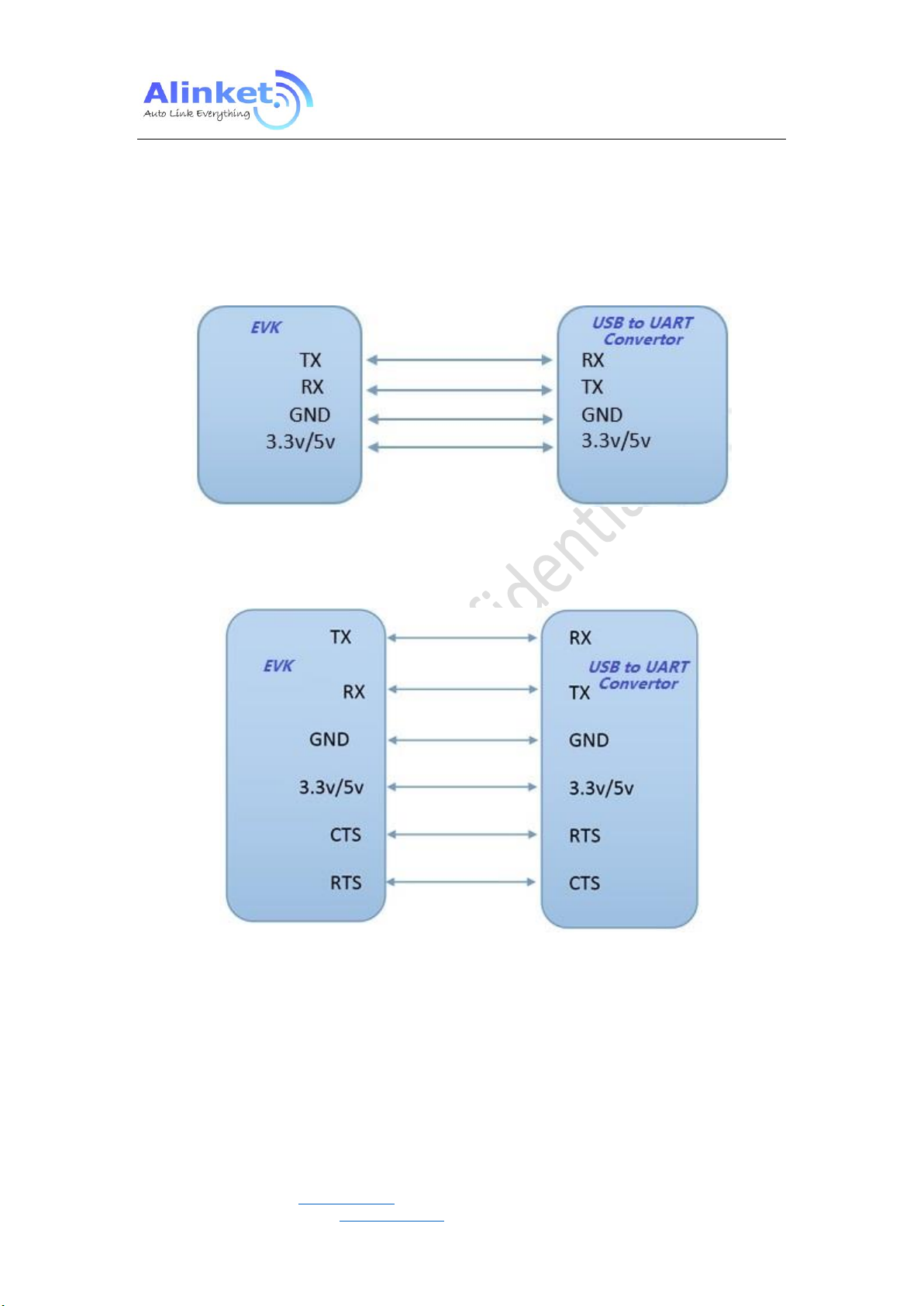
4.1.2.2 USB to UART Convertor
The convertor is used for connecting between the EVK with PC. Its PIN definition is described below.
Figure 15 Without HW Flow Control
Figure 16 With HW Flow Control
Table 8 USB – UART Convertor PIN
Alinket Technology Corp. www.alinket.com Proprietary & Confidential Information 21
All Rights Reserved. E-mail: sales@alinket.com
4.1.3 Set Up
Connect the EVK and PC (Host) with USB-to-Serial converter.
4.1.3.1 Connection Diagram
Figure 17 Connection Diagram – Without HW Flow Control
ALXC12B User Manual
Figure 18 Connection Diagram – With HW Flow Control
Alinket Technology Corp. www.alinket.com Proprietary & Confidential Information 22
All Rights Reserved. E-mail: sales@alinket.com

4.1.3.2 Connection Map
Figure 19 Connection Map – Normal Case
ALXC12B User Manual
Figure 20 Connection Map – Roaming
Figure 21 Connection Map - EAP
Alinket Technology Corp. www.alinket.com Proprietary & Confidential Information 23
All Rights Reserved. E-mail: sales@alinket.com

ALXC12B User Manual
4.2 Process Introduction
4.2.1 Wi-Fi Transparent Mode
ALXC12B supports serial interface transparent transmission mode. Under transparent mode,
users need only to configure the necessary parameters. After power on, the module can be
connected to the master. TCP & UDP is common protocol for network connections.
4.2.1.1 TCP
Step1. Set up a server on a computer attached to an AP.
Figure 22 Set up a Server
Step2. Install Alinket Flashlink software on a mobile device, which can join the same AP as the
computer.
Alinket Technology Corp. www.alinket.com Proprietary & Confidential Information 24
All Rights Reserved. E-mail: sales@alinket.com

Step3. Network configuration by using Flashlink software as shown below.
ALXC12B User Manual
Figure 23 Network Configuration – Flashlink
Step4. WIFI SSID is the name of the AP that the computer attached to.
Step5. Server URL is the server IP and port number.
Step6. Stop/Start button will launch the “Flashlink” function.
Step7. When configuration is finished, click “Start” button, if flash link is successful, the module
will automatically configured.
Alinket Technology Corp. www.alinket.com Proprietary & Confidential Information 25
All Rights Reserved. E-mail: sales@alinket.com

ALXC12B User Manual
Step8. After the module connects to the server successfully, message can be exchanged between
the computer and the module as shown in below figure.
Figure 24 TCP Connected
4.2.1.2 UDP
Step1. Set up a client on computer, configure the UDP setting.
Step3. Repeat step 2~7 in chapter 4.2. But server URL in step 3 should be udp://XXX.XXX.X.X:port
number.
Alinket Technology Corp. www.alinket.com Proprietary & Confidential Information 26
All Rights Reserved. E-mail: sales@alinket.com

ALXC12B User Manual
1
2
3
4
4.2.2 ACM Mode for Wi-Fi
4.2.2.1 ACMTH
ACMTH (ACM Test Host) is a tool for ACM test simulated as a host. It includes mainly 4 functions.
Figure 25 ACMTH Function Blocks
Part 1: Show different function which can set module in different status.
Part 2: Each function in part1 have child configuration.
Part 3: Execute the current setting or get message from module.
Part 4: Show the send and receive message.
Alinket Technology Corp. www.alinket.com Proprietary & Confidential Information 27
All Rights Reserved. E-mail: sales@alinket.com

ALXC12B User Manual
4.2.2.2 Configuration Process
Users can send ACM commands to module for executions such as ON or OFF WIFI, Join or Leave
AP and so on. It is described below on how to use ACM tool to send command. Detailed
commands please refer to AN_ACM_User Manual.
Step1. Connect EVK and PC with USB-to-Serial
Step2. Open ACMTH
Step3. Click “Add” to add port in “Module Port” (Double click/right click port to open or close port)
Figure 26 Add Serial Port in ACMTH
Step4. Choice message you want to send in “Request Messages”
Step5. Clink “Send” button. If Send message successful, tool can get response from module
Figure 27 ACM Operation
Alinket Technology Corp. www.alinket.com Proprietary & Confidential Information 28
All Rights Reserved. E-mail: sales@alinket.com

4.2.2.3 Roaming
Step1: setup test environment as below:
ALXC12B User Manual
Figure 28 Roaming Setup
Note: The SSID and password of AP1 and AP2 must be the same.
Step2: Start TCP or UDP traffic between module and server
Step3: Check AP info and RSSI by ACM command “Get AP Information”
Figure 29 Get AP Information
Alinket Technology Corp. www.alinket.com Proprietary & Confidential Information 29
All Rights Reserved. E-mail: sales@alinket.com

ALXC12B User Manual
Parameter
Value
Unit
Trigger
-1 to -100
dBm
Delta
1 to 100
dBm
Period
1 to 100
Second
Step4: Set roaming parameters.
Figure 30 Set Roaming Parameters
Table 9 Roaming Parameters
Step5: Move the module from the coverage of AP1 to AP2, check the BSSID and RSSI of AP2.
Note: A successful roaming must
1) IP address of module won’t change.
2) Traffic won’t stop.
Alinket Technology Corp. www.alinket.com Proprietary & Confidential Information 30
All Rights Reserved. E-mail: sales@alinket.com

ALXC12B User Manual
4.2.2.4 EAP
Step1. Open port with baud rate as SW default
Step2. Click “EAP Configuration” tool in ACM tool and configure it as follows
Figure 31 EAP Configuration
Note: Phase1 Method must be ”PEAP”; Phase2 Method can be “GTC” or “MsChapV2”;
Authentication ID and Password is defined by Radius server.
Step3: Send “WIFI on” message;
Step4: Fill in destination AP SSID, and set security as “Wpa2_8021X_Eap_Secure”, leave password as
blank, then send “WIFI Join” message.
Figure 32 Wi-Fi Join for EAP
Alinket Technology Corp. www.alinket.com Proprietary & Confidential Information 31
All Rights Reserved. E-mail: sales@alinket.com

ALXC12B User Manual
4.2.3 ACM Mode for BT
4.2.3.1 EVK to PC
Step1: ALXC12B EVK connects to the USB port of your PC and gets this EVK COM port (COM3)
from Device Manager of PC.
Step2: Open ACMTH tool and send “WIFI on” command.
Figure 33 Wi-Fi On
Step3: After Wi-Fi On successfully, send “BT On” command.
Figure 34 BT On
Alinket Technology Corp. www.alinket.com Proprietary & Confidential Information 32
All Rights Reserved. E-mail: sales@alinket.com
ALXC12B User Manual
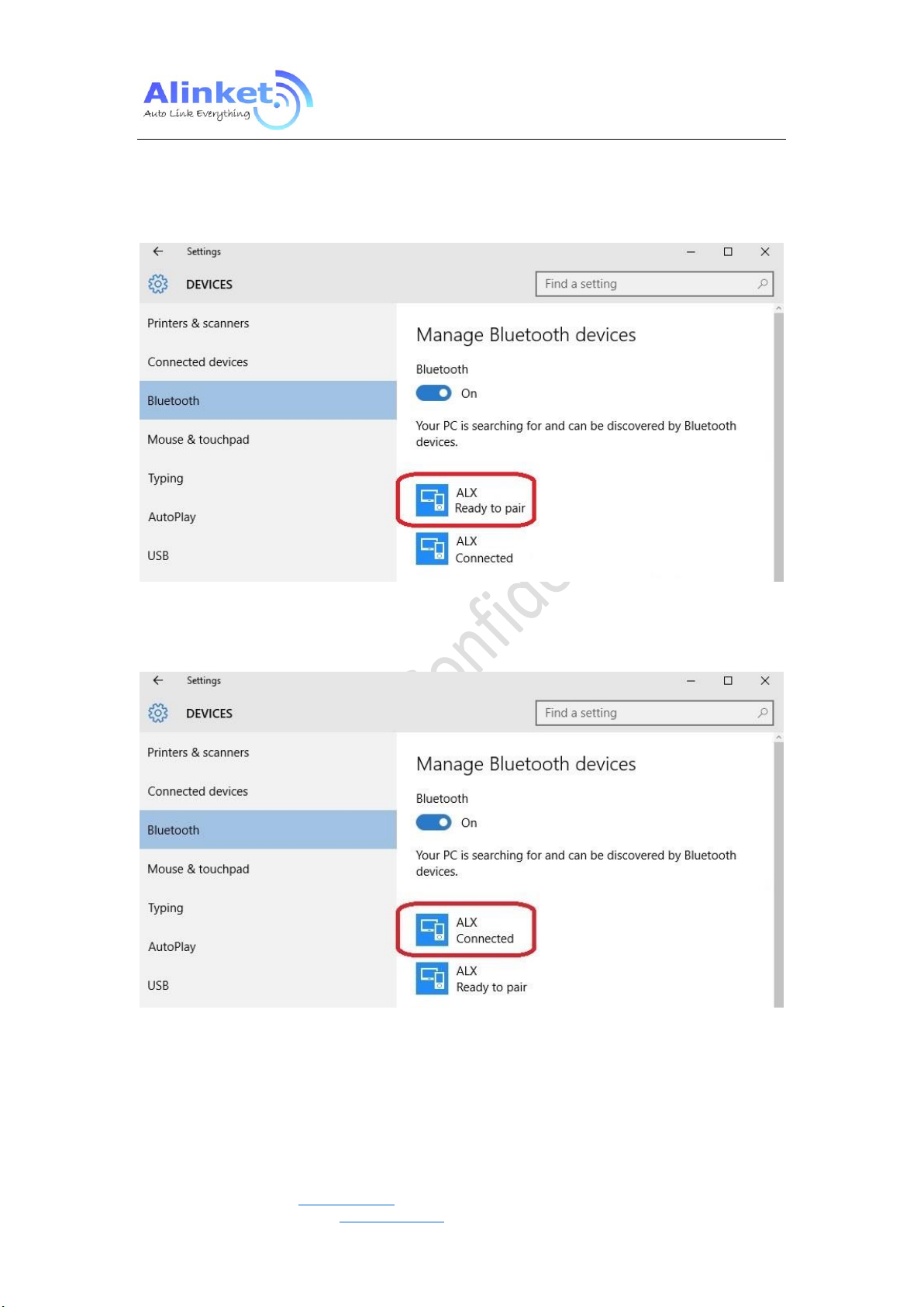
Step4: Setting BT mode to ”slave “ and send “set BT Mode” on ACMTH tool.
Step5: Connect with PC Bluetooth, Click “win10”---“setting”—“device”---"Bluetooth” and pair
corresponding device in list.
Figure 35 Ready for Pairing
Step6: Waiting for connection successfully.
Figure 36 Pairing Successful
Alinket Technology Corp. www.alinket.com Proprietary & Confidential Information 33
All Rights Reserved. E-mail: sales@alinket.com

ALXC12B User Manual
Step7: Open Alinket RFCOMM Test Host tool, chose corresponding device and click “connect”
Figure 37 Connecting through RFCOMM
Step8: ALXC12B should receive a message indicating that the connecting was successful.
Figure 38 Connected Status Indication
Alinket Technology Corp. www.alinket.com Proprietary & Confidential Information 34
All Rights Reserved. E-mail: sales@alinket.com

ALXC12B User Manual
4.2.3.2 EVK to EVK
Step1: Prepare 2ps ALXC12B, one is as master role and the other is as slave role. For example,
ALXC12B_Local port com3 is as master and ALXC12B_Local port com307 is as slave;
Figure 39 Master & Slave Test Connection
Step2: Send “WIFI ON” and “BT ON” command respectively from local port COM3 and COM307.
Figure 40 Port Configuration by ACMTH
Step3: Send “Enable BT advertise” from the slave role (local port com307).
Alinket Technology Corp. www.alinket.com Proprietary & Confidential Information 35
All Rights Reserved. E-mail: sales@alinket.com

ALXC12B User Manual
Step4: Use “BT Master Connect” to setup the connection with slave’s MAC address.
Figure 41 Setup Connection between Master & Slave
Step5: Master gets response with success return code and connect up indication.
Figure 42 Connection Successful Indication
Alinket Technology Corp. www.alinket.com Proprietary & Confidential Information 36
All Rights Reserved. E-mail: sales@alinket.com

4.2.4 ACM Mode for BLE
Same procedure as ACM Mode for BT
Step1: Add local port.
Step2: Open ACMTH tool and send “WIFI on” command.
Step3: After Wi-Fi On successfully, send “BLE On” command.
Figure 43 BLE On
ALXC12B User Manual
Step4. Chose message you want to send in “Request Messages”
Step5. Clink “Send” button. If Send message successful, tool can get response from module
Figure 44 BLE Operation
Alinket Technology Corp. www.alinket.com Proprietary & Confidential Information 37
All Rights Reserved. E-mail: sales@alinket.com

5. Work Condition
Symbol
Description
Min.
Max.
Unit
Tg
General operating temperature
-30
85
°C
Ts
Storage temperature
-40
85
°C
VDDIO
IO power supply
2.8
3.6
V
VDDBAT
Power supply
2.8
3.6
V
MSL
Moisture Sensitivity Level
3
RoHS
Restriction of Hazardous Substances
Compliant
Symbol
Min.
Typ.
Max.
Unit
VDD
3.0
3.3
3.6
V
Operating temperature
-20°C to 70°C
Storage Temperature
5°C to 35°C
Humidity Range
40% ~ 70%, relative humidity
5.1 Range of Operation
Table 10 Range of Operation – General Specification
5.2 Recommended Operation Range
ALXC12B User Manual
Table 11 Recommended Voltage
Table 12 Recommended Temperature and Humidity
Alinket Technology Corp. www.alinket.com Proprietary & Confidential Information 38
All Rights Reserved. E-mail: sales@alinket.com

6. Manufacturing
6.1 Recommended Reflow Profile
Referred to IPC/JEDEC Standard,
Peak Temperature < 250 °C,
Number of Times <= 2Times.
ALXC12B User Manual
Figure 45 Reflow Profile
6.2 ROHS Declaration
To the best of our present knowledge, given our supplier declarations, this product does not contain
any substance that is banned by EU RoHS Directive 2011/65/EU and its amendment directives – XRF.
RoHS restricted substances are list below.
Cadmium (Cd)
Lead (Pb)
Mercury (Hg)
Hexavalent Chromium (Cr(VI))
Polybrominated biphenyls (PBBs)
Polybrominated diphenylether (PBDEs)
Alinket Technology Corp. www.alinket.com Proprietary & Confidential Information 39
All Rights Reserved. E-mail: sales@alinket.com

7. Ordering Information
ALXC12A
Wi-Fi 2.4GHz + BT 4.0 Combo IoT Controller, On-Board Antenna
ALXC12B
Wi-Fi 2.4GHz + BT4.0 Combo IoT Controller, External Antenna (U.FL)
Table 13 Order Information
8. Technical Support
For technical support, please contact:
Alinket Electronic Technology (Shanghai) Co., Ltd.
E-Mail: support@alinket.com
Tel: +86 21 6104 8128
ALXC12B User Manual
Address: Floor 4, No.10, Lane 198, Zhangheng Road, Shanghai, 201204 P. R. China
9. Reference
[1] ALXC12B Product Brief, Alinket
[2] ALXC12B Schematic Diagram, Alinket
[3] ALXC12B Datasheet, Alinket
Alinket Technology Corp. www.alinket.com Proprietary & Confidential Information 40
All Rights Reserved. E-mail: sales@alinket.com

ALXC12B User Manual
-16QAM
16Quadrature Amplitude Modulation
-64QAM
64Quadrature Amplitude Modulation
-ADC
Analog-to-Digital Converter
-ARM
Advanced RISC Machines
-ART
Adaptive Real-Time Memory
-AiDK
Alinket IoT Development Kit
-AES
Audio Engineering Society
-BPSK
Binary Phase Shift Keying
-CMOS
Complementary Metal Oxide Semiconductor
-CE
Conformite Europeenne
-CRC
Cyclic Redundancy Code
-CCK
Complementary Code Keying
-DAC
Digital-to-Analog Converter
-DMIPS
Dhrystone Million Instructions executed Per Second
-DSP
Digital Signal Processor
-DMA
Direct Memory Access
-DSS
Direct Sequence Spread Spectrum
-EAP
Extension Authentication Protocol
-EVK
Evaluation Kit
-EVM
Error Vector Magnitude
-FIFO
First In First Out
-GPIO
General-Purpose Input-Output
-HNP
Host Negotiation Protocol
-I2C
Inter-Integrated Circuit
-I2S
Inter-IC Sound
-ISM
Industrial
-IEEE
Institute of Electrical and Electronics Engineers
-IP
Internet Protocol
-IC
Integrated Circuit
-JTAG
Joint Test Action Group
-LQFP
Low-profile Quad Flat Package
-MAC
Medium Access Control
-MSL
Moisture Sensitivity Level
-OFDM
Orthogonal Frequency Division Multiplexing
-PWM
Pulse Width Modulation
-PER
Packet Error Rate
-PEAP-GTC
Protected Extensible Authentication Protocol- Good Till Cancelled
-PEAP-MSCHAP
Microsoft Challenge Handshake Authentication Protocol
Appendix: Acronyms and Abbreviations
The following list of acronyms and abbreviations may appear in this document.
Alinket Technology Corp. www.alinket.com Proprietary & Confidential Information 41
All Rights Reserved. E-mail: sales@alinket.com

ALXC12B User Manual
-PBB
Poly Brominated Biphenyl
-PBDE
Poly Brominated Biphenyl Ether
-PLL
Phase Locked Logic
-QPSK
Quadrature Phase Shift Keying
-ROHS
Restriction of Hazardous Substances
-RC
Real Clock
-RTC
Real Time Clock
-RF
Radio Frequency
-SPI
Serial Peripheral Interface
-SDIO
Secure Digital Input and Output Card
-SRAM
Static Random Access Memory
-SKU
Stock Keeping Unit
-SRP
Session Request Protocol
-TLS
Transport Layer Security
-TCP
Transmission Control Protocol
-TKIP
Temporal Key Integrity Protocol
-USBH
Universal Serial Bus Host Mode
-USBD
Universal Serial Bus Device Mode
-UDP
User Datagram Protocol
-UART
universal asynchronous receiver/transmitter
-WiFi
Wireless Fidelity
-WLAN
Wireless Local Area Network
-WAPI
WLAN Authentication and Privacy Infrastructure
-WPA
Wi-Fi Protected Access
Alinket Technology Corp. www.alinket.com Proprietary & Confidential Information 42
All Rights Reserved. E-mail: sales@alinket.com

FCC Statement
Any Changes or modifications not expressly approved by the party responsible for compliance could
void the user’s authority to operate the equipment.
This device complies with part 15 of the FCC Rules. Operation is subject to the following two conditions:
(1) This device may not cause harmful interference, and
(2) This device must accept any interference received, including interference that may cause undesired
operation.
FCC Radiation Exposure Statement:
This equipment complies with FCC radiation exposure limits set forth for an uncontrolled
environment .This equipment should be installed and operated with minimum distance 20cm between
the radiator& your body.
FCC Label Instructions
The outside of final products that contains this module device must display a label referring to the
enclosed module. This exterior label can use wording such as:
“Contains Transmitter Module FCC ID:2AELJ-ALXC12B" or “Contains FCC ID:2AELJ-ALXC12B” Any
similar wording that expresses the same meaning may be used.
Note: This equipment has been tested and found to comply with the limits for a Class B digital device,
pursuant to part 15 of the FCC Rules. These limits are designed to provide reasonable protection
against harmful interference in a residential installation. This equipment generates, uses and can
radiate radio frequency energy and, if not installed and used in accordance with the instructions,
may cause harmful interference to radio communications. However, there is no guarantee that
interference will not occur in a particular installation. If this equipment does cause harmful
interference to radio or television reception, which can be determined by turning the equipment off
and on, the user is encouraged to try to correct the interference by one or more of the following
measures:
—Reorient or relocate the receiving antenna.
—Increase the separation between the equipment and receiver.
—Connect the equipment into an outlet on a circuit different from that to which the receiver is
connected.
—Consult the dealer or an experienced radio/TV technician for help.
 Loading...