

Page 1

User Manual
A-LINK WNAP4G
WLAN Gigabit Router
V2.0_20121122
Page 2

2
TABLE OF CONTENTS
COPYRIGHT ..................................................................................................................... 4
FCC INTERFERENCE STATEMENT ................................................................................ 4
CHAPTER 1 INTRODUCTION .......................................................................................... 5
1.1 PACKAGE LIST ...................................................................................................... 5
1.2 HARDWARE INSTALLATION ................................................................................. 6
CHAPTER 2 GETTING STARTED WITH EASY SETUP UTILITY ................................... 9
2.1 EASY SETUP BY WINDOWS UTILITY .................................................................. 9
2.2 EASY SETUP BY CONFIGURING WEB PAGES ................................................. 14
CHAPTER 3 CONFIGURATIONS- BASIC NETWORK .................................................. 19
3.1 LAN(WIFI) & WAN SETUP ............................................................................ 20
3.1.1 NETWORK SETUP........................................................................................ 21
3.1.2 IPV6 ............................................................................................................... 38
3.1.3 WIRELESS SETTINGS ................................................................................. 43
3.1.4 ADVANCED WIRELESS SETTINGS............................................................. 49
3.2 NAT................................................................................................................ 50
3.2.1 VIRTUAL SERVER ........................................................................................ 50
3.2.2 SPECIAL AP .................................................................................................. 52
3.2.3 LOOPBACK ................................................................................................... 53
3.2.4 DMZ ............................................................................................................... 53
3.3 ROUTING ...................................................................................................... 54
3.3.1 STATIC ROUTING......................................................................................... 54
3.3.2 DYNAMIC ROUTING ..................................................................................... 55
3.4 CLIENT/SERVER/PROXY ................................ ................................ ............. 55
3.4.1 DHCP SERVER ............................................................................................. 56
3.4.2 DYNAMIC DNS .............................................................................................. 58
CHAPTER 4 CONFIGURATIONS- ADVANCED NETWORK ......................................... 59
4.1 FIREWALL ..................................................................................................... 59
4.1.1 FIREWALL STATUS ...................................................................................... 60
4.1.2 PACKET FILTERS ......................................................................................... 61
4.1.3 DOMAIN FILTERS ......................................................................................... 63
4.1.4 URL BLOCKING ............................................................................................ 64
4.1.5 MAC CONTROL ............................................................................................ 65
4.1.6 OTHERS ................................................................................................ ........ 66
4.2 QOS (QUALITY OF SERVICE) ...................................................................... 67
4.2.1 SMART QOS ................................................................................................. 68
4.2.2 USER DEFINED RULE-BASED QOS ........................................................... 70
A-LINK WNAP4G User Manual
Page 3

3
4.3 VLAN ............................................................................................................. 75
4.4 GREEN .......................................................................................................... 76
4.5 MANAGEMENT ............................................................................................. 76
4.5.1 UPNP ............................................................................................................. 76
4.5.2 SNMP ............................................................................................................ 77
4.5.3 TR-069 REMOTE MANAGEMENT ................................................................ 79
CHAPTER 5 CONFIGURATIONS - APPLICATIONS ..................................................... 80
5.1 USSD ............................................................................................................. 80
5.2 NAS ............................................................................................................... 81
5.2.1 DISK UTILITY ................................................................................................ 81
5.2.2 SAMBA SERVER .......................................................................................... 82
5.2.3 FTP SERVER CONFIGURATION ................................................................. 82
5.2.4 ACCESS CONTROL...................................................................................... 83
5.2.5 ITUNE SERVER ............................................................................................ 84
5.2.6 DOWNLOAD ASSISTANT ............................................................................. 85
5.2.7 DOWNLOAD STATUS ................................................................................... 89
5.2.8 WEB HDD ...................................................................................................... 89
5.2.9 MISCELLANEOUS ........................................................................................ 90
CHAPTER 6 SYSTEM .................................................................................................... 91
6.1 SYSTEM INFORMATION .............................................................................. 91
6.2 SYSTEM STATUS ......................................................................................... 92
6.2.1 WEB LOG ...................................................................................................... 92
6.2.2 SYSTEM LOG ............................................................................................... 92
6.2.3 EMAIL ALERT ............................................................................................... 93
6.3 SYSTEM TOOLS ........................................................................................... 94
6.3.1 ACCOUNT & PASSWORD ............................................................................ 94
6.3.2 FW UPGRADE .............................................................................................. 94
6.3.3 SYSTEM TIME............................................................................................... 95
6.3.4 OTHERS ................................................................................................ ........ 96
6.4 SCHEDULING ............................................................................................... 98
6.5 MMI ................................................................................................................ 99
CHAPTER 7 TROUBLESHOOTING ............................................................................. 100
APPENDIX A. SPEC SUMMARY TABLE ..................................................................... 105
APPENDIX B. LICENSING INFORMATION ................................................................. 107
* Please press the “Ctrl” key to use the bookmark for .doc file.
* Please click the bookmark icon on the left hand side to check bookmark list for .pdf file.
A-LINK WNAP4G User Manual
Page 4

4
Copyright
The contents of this publication may not be reproduced in any part or as a whole, stored,
transcribed in an information retrieval system, translated into any language, or
transmitted in any form or by any means, mechanical, magnetic, electronic, optical,
photocopying, manual, or otherwise, without the prior written permission.
Trademarks
All products, company, brand names are trademarks or registered trademarks of their
respective companies. They are used for identification purpose only. Specifications are
subject to be changed without prior notice.
FCC Interference Statement
This equipment has been tested and found to comply with the limits for a Class B digital
device pursuant to Part 15 of the FCC Rules. These limits are designed to provide
reasonable protection against radio interference in a commercial environment. This
equipment can generate, use and radiate radio frequency energy and, if not installed and
used in accordance with the instructions in this manual, may cause harmful interference
to radio communications. Operation of this equipment in a residential area is likely to
cause interference, in which case the user, at his own expense, will be required to take
whatever measures are necessary to correct the interference.
CE Declaration of Conformity
This equipment complies with the requirements relating to electromagnetic compatibility,
EN 55022/A1 Class B.
A-LINK WNAP4G User Manual
Page 5
5
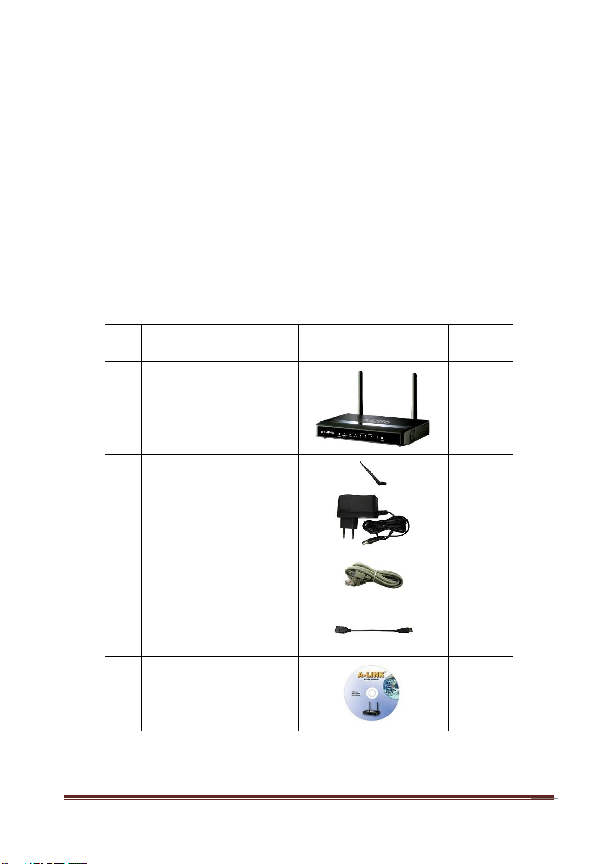
Chapter 1 Introduction
Item
s
Description
Contents
Quantity
1
WNAP4G Router
1
2
SMA antenna
2
3
Power adapter
1
4
RJ-45 cable
1
5
USB cable
1
6
CD 1
The WNAP4G Router is a high-performance device that supports gigabit Ethernet,
wireless networking at home, work, or in a public place. The WNAP4G Router supports
3G/4G USB modems, either WCDMA or EVDO and even HSPA and LTE as well, and
supports wireless data transfers up to 300M bps, and wired data transfers up to
100Mbps. The WNAP4G Router is compatible with industry security features.
1.1 Package List
A-LINK WNAP4G User Manual
Page 6
6
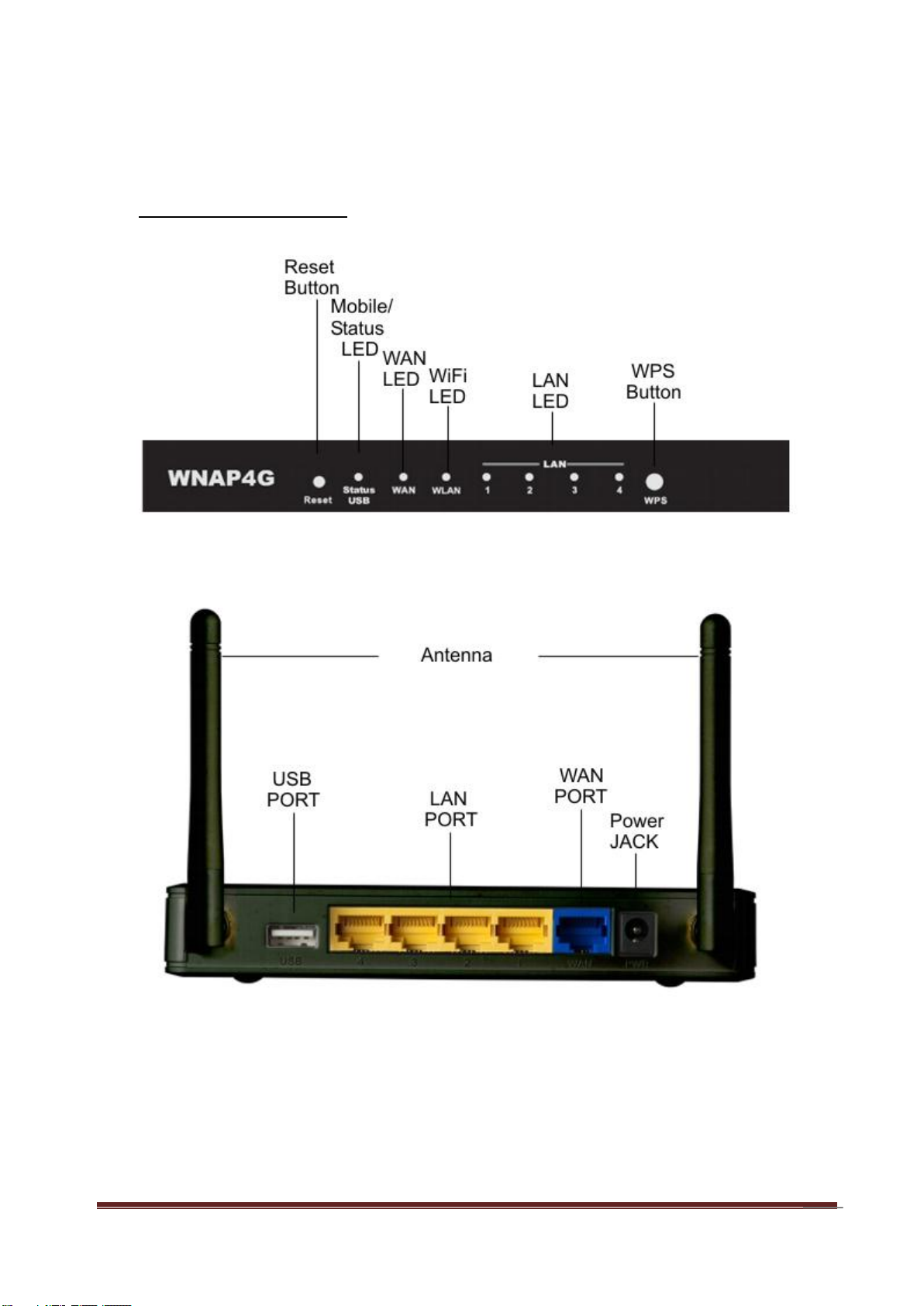
1.2 Hardware Installation
A. Hardware configuration
A-LINK WNAP4G User Manual
Page 7

7
B. LED indicators
LED
Indicator
Description
Status/USB
Green and Blink once
per second
No external USB device is attached,
and this router is working.
Green and Steady On
An external USB device is attached
Green and Blinking
Data packet transferred via attached
USB device (e.g. USB drive, 3G/4G
dongle)
Ethernet WAN
Green and Steady On
Ethernet WAN connection is
established
Green and Blinking
Data packet transferred via Ethernet
WAN
WLAN
Green and Blinking
Data packet transferred via WiFi
Green and Fast
Blinking
In WPS PBC mode
OFF
WiFi radio is disabled
Ethernet LAN 1~4
Green and Steady On
Ethernet LAN connection is
established
Green and Blinking
Data packet transferred via Ethernet
LAN
A-LINK WNAP4G User Manual
Page 8
8
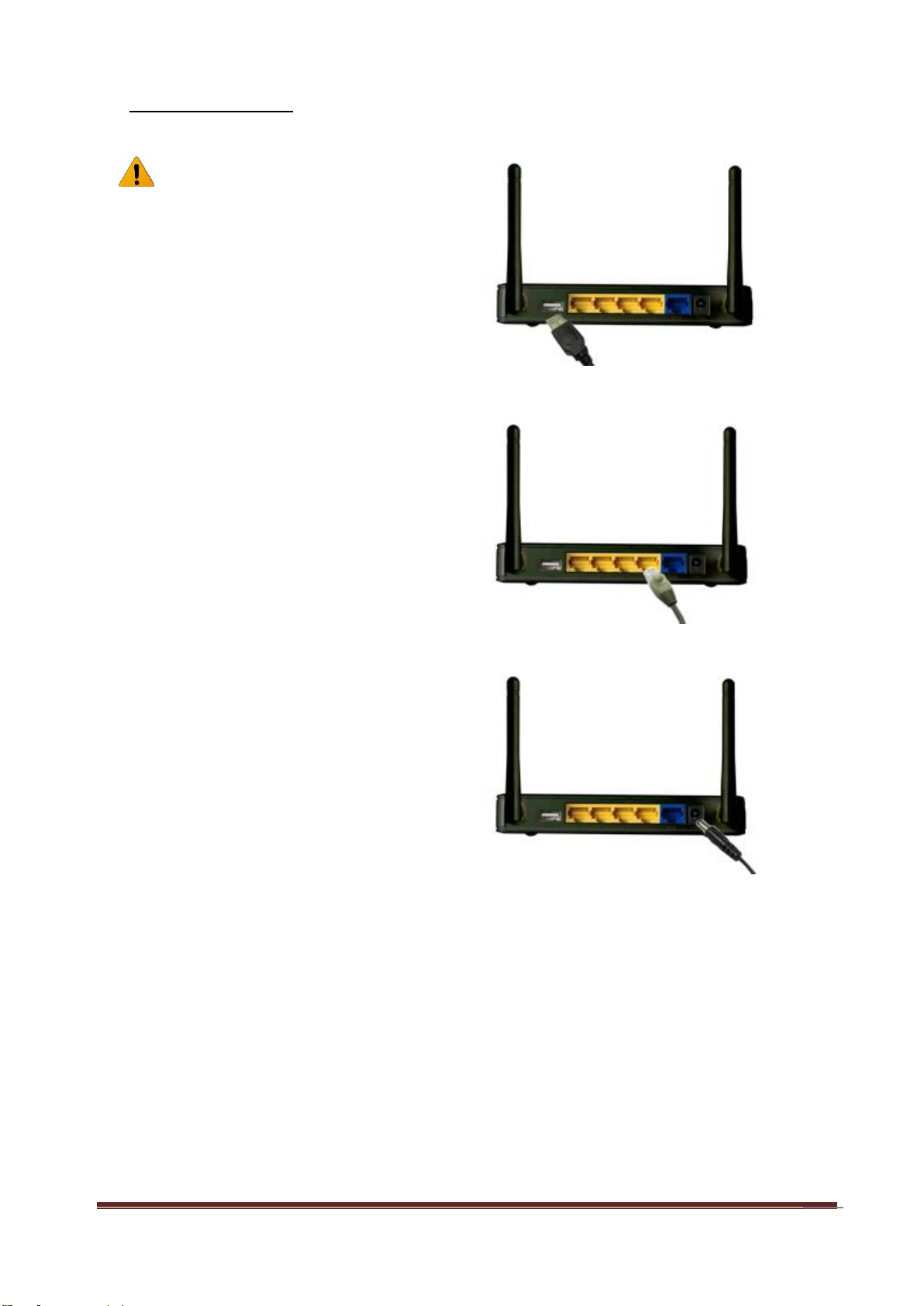
C. Installation Steps
Note: DO NOT connect the router
to power before performing the
installation steps below.
Step 1.
Plug a USB modem into USB port.
Step 2.
Insert RJ45 cable into LAN Port on the
back panel of the router. Then plug the
other end of into computer.
Step 3.
Plug the power jack into the receptor on
the back panel of the router. Then plug
the other end into a wall outlet or power
strip.
A-LINK WNAP4G User Manual
Page 9
9
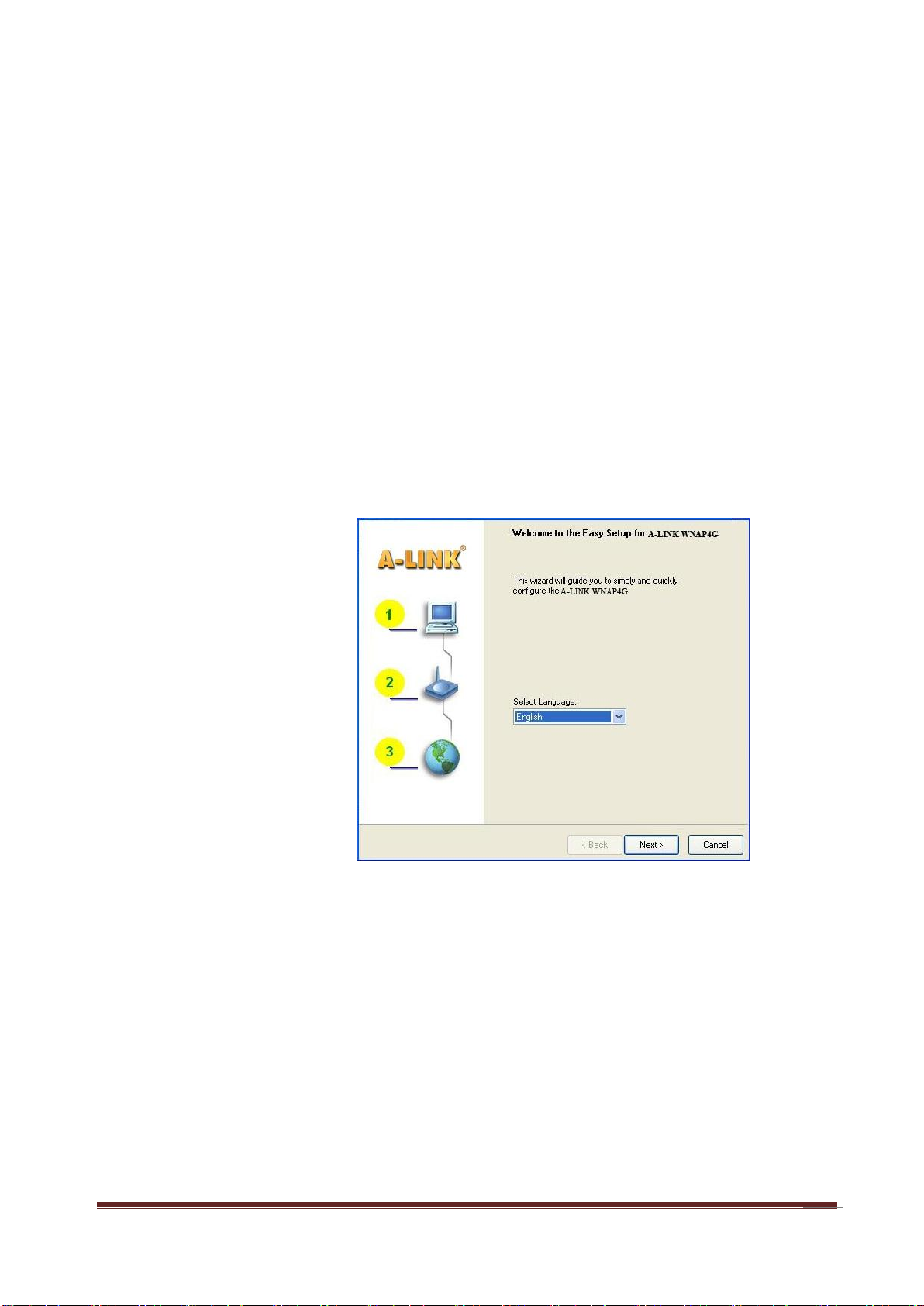
Step 1:
Install the Easy Setup
Utility from the provided
CD then follow the steps
to configure the device.
Step 2:
Select Language then
click “Next” to continue.
Chapter 2 Getting Started with Easy Setup Utility
There are two approaches for you to set up the WNAP4G Router quickly and easily. One
is through executing the provided Windows Easy Setup Utility on your PC, and the other
is through browsing the device web pages and configuration.
2.1 Easy Setup by Windows Utility
A-LINK WNAP4G User Manual
Page 10
10
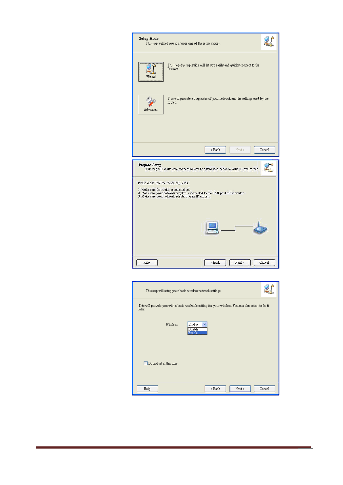
Step 3:
Then click the “Wizard”
to continue.
Step 4:
Click “Next” to continue.
Step 5:
Select Wireless Enable,
and then click “Next” to
continue.
A-LINK WNAP4G User Manual
Page 11
11
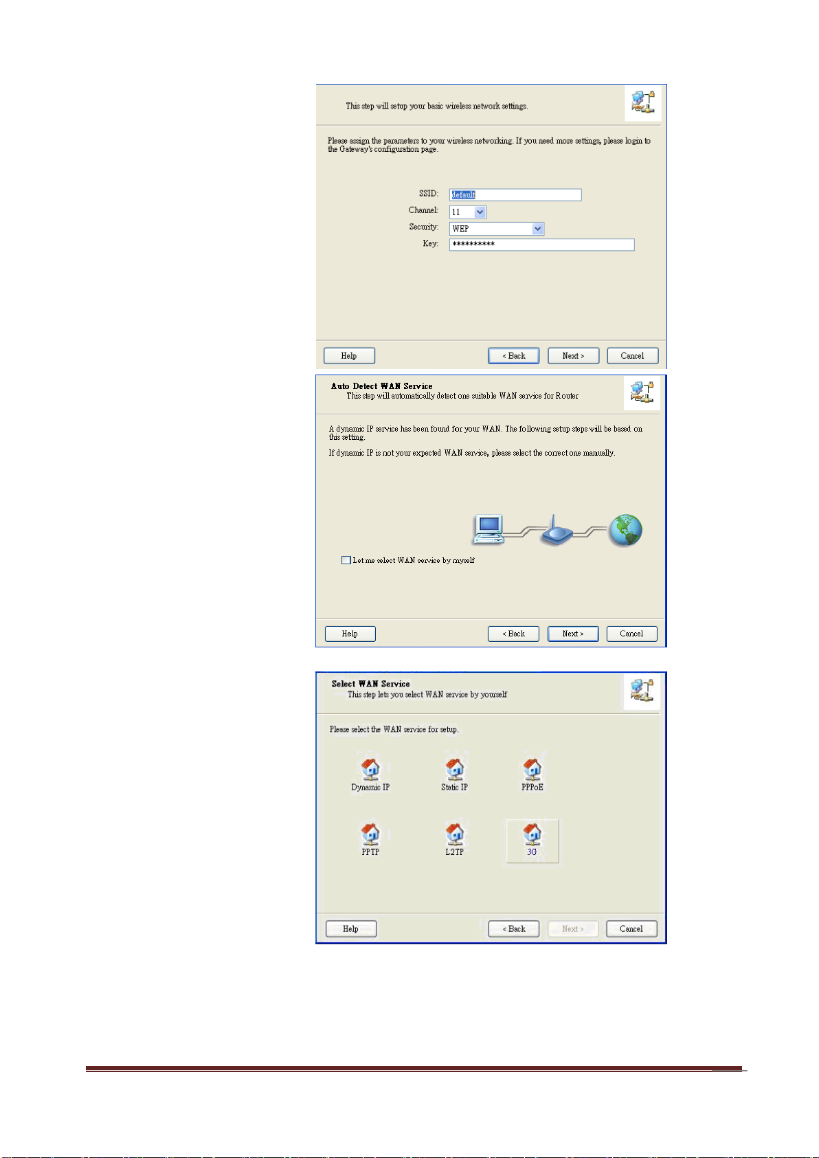
Step 6:
Enter SSID, Channel
and Security options,
and then click “Next” to
continue.
Step 7:
Click” Let me select
WAN service by myself”
to select WAN service
manually.
Step 8:
Select 3G Service by
clicking 3G icon to
continue.
A-LINK WNAP4G User Manual
Page 12
12
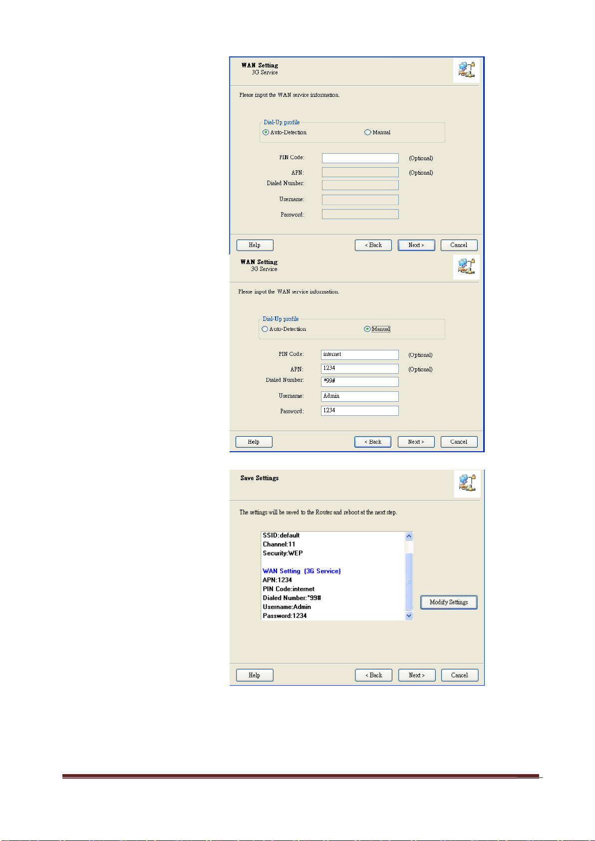
Step 9-1:
Select “Auto-Detection”
and the Utility will try to
detect and configure the
required 3G service
settings automatically.
Click “Next” to continue.
Step 9-2:
Or you can select
“Manual” and manually
fill in the required 3G
service settings provided
by your ISP.
Click “Next” to continue.
Step 10:
Click “Next” to save your
setting.
A-LINK WNAP4G User Manual
Page 13
13
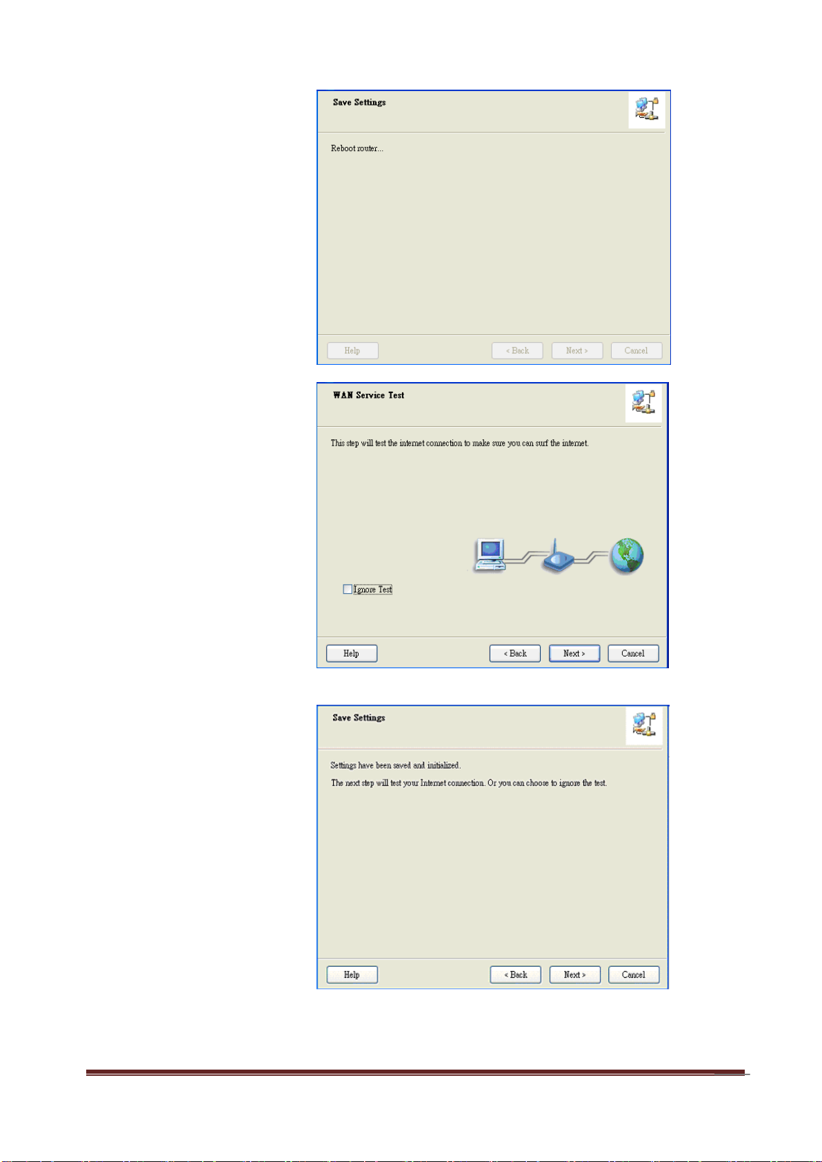
Step 11:
The WNAP4G Router is
rebooted to make your
entire configuration take
effect.
Step 12:
Click “Next” to test the
Internet connection or
you can ignore test.
Step 13:
Click “Next” to test WAN
Networking service.
A-LINK WNAP4G User Manual
Page 14
14
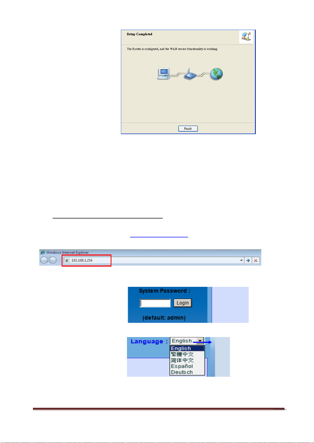
Step 14:
Setup is completed.
A. Browse to Activate the Setup Wizard
Step 1: Type in the IP Address (http://192.168.1.254)
Step 2:
Type in the default
password “admin” in the
System Password and
then click “login” button.
Select your language.
2.2 Easy Setup by Configuring Web Pages
You can also browse web UI to configure the device.
A-LINK WNAP4G User Manual
Page 15
15
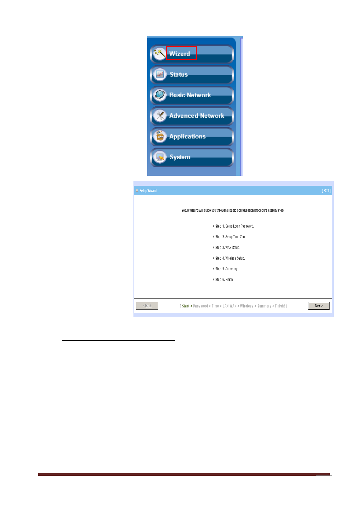
Step 3:
Select “Wizard” for basic
settings with simple way.
Step 4:
Press “Next” to start the
Setup Wizard.
B. Configure with the Setup Wizard
A-LINK WNAP4G User Manual
Page 16
16
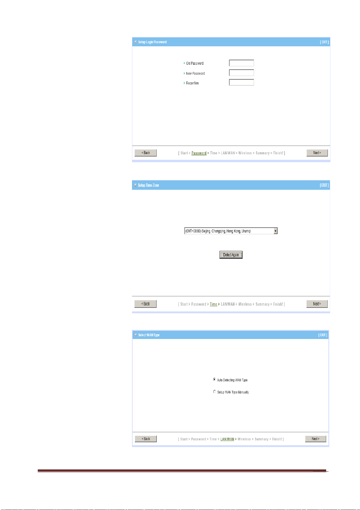
Step 1:
Change System
Password.
Set up your system
password.
(Default:admin)
Step 2:
Select Time Zone.
Step 3:
Select WAN Type.
Choose Auto-Detecting
or Manually to set WAN
Type.
A-LINK WNAP4G User Manual
Page 17
17
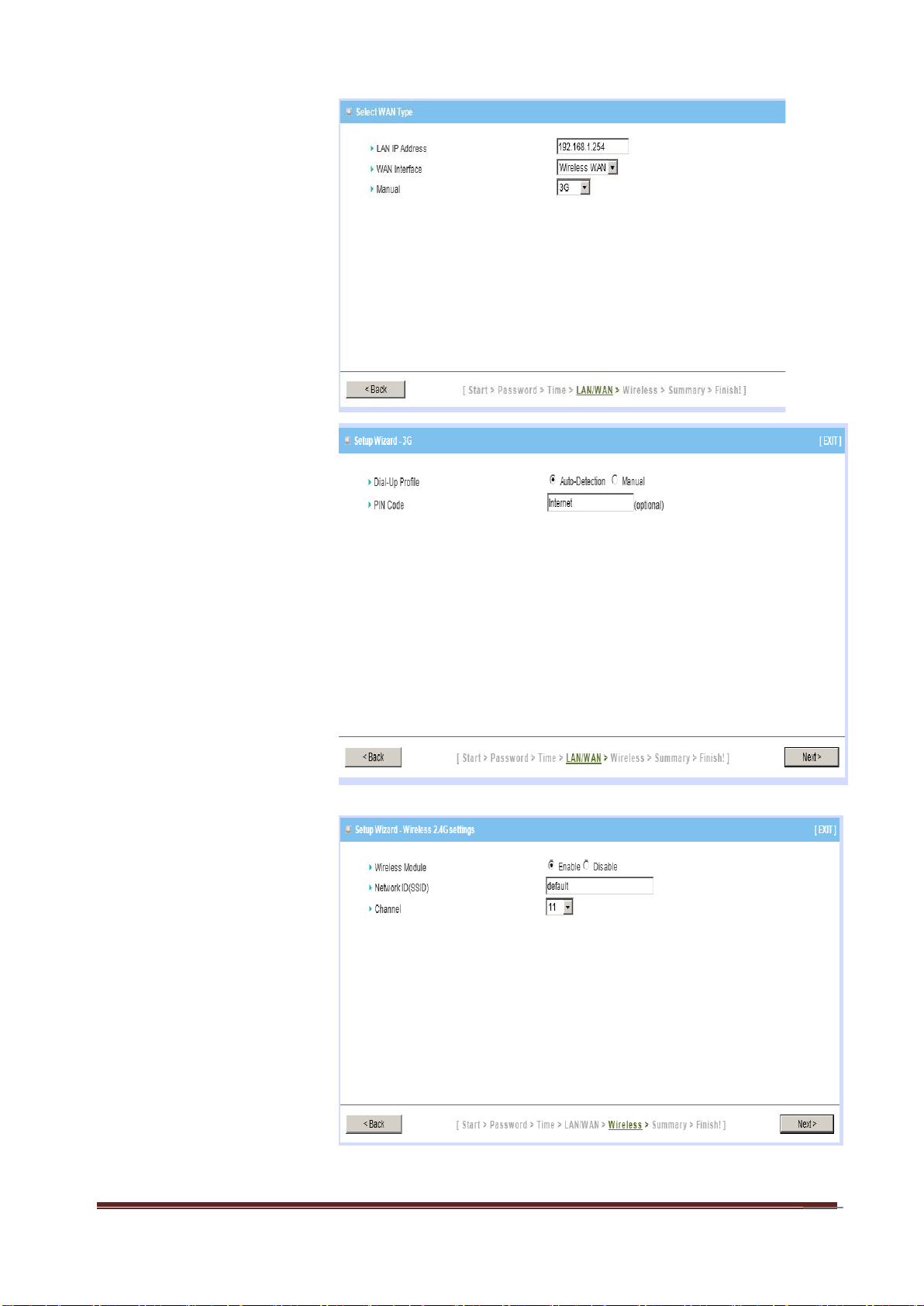
Step 4:
Select Wan Type.
If you want to use 3G
service as the main
internet access, please
set the WAN interface as
“Wireless WAN” and the
WAN type as “3G”.
Step 5:
3G Mode.
Select Auto-Detection
then click “Next” to
continue.
Step 6:
Set up your Wireless
Network.
Set up your SSID.
A-LINK WNAP4G User Manual
Page 18
18
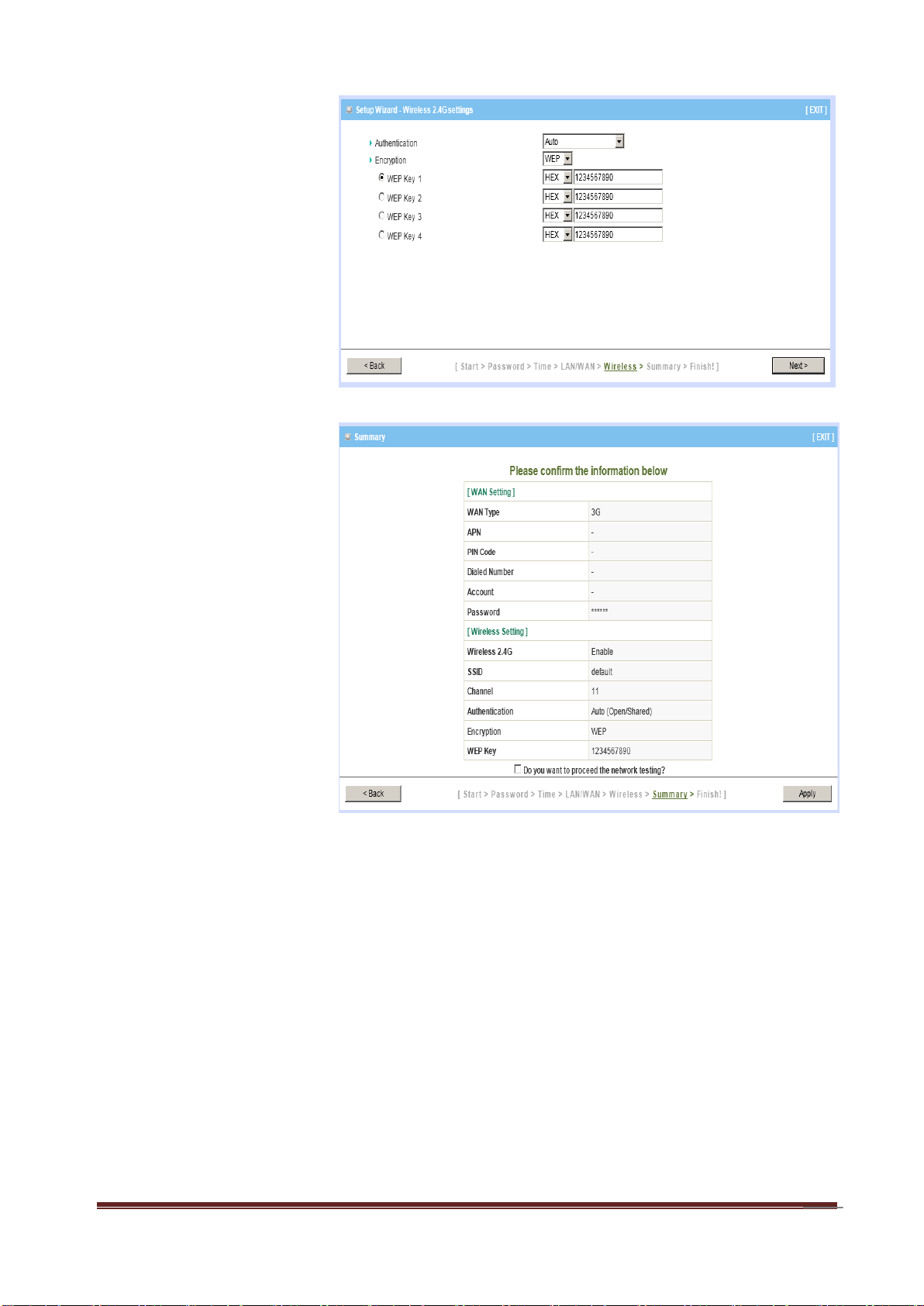
Step 7:
Setup your Encryption
key here, and then click
“Next” to continue.
Step 8:
Apply your Setting.
Then click Apply Setting.
A-LINK WNAP4G User Manual
Page 19
19
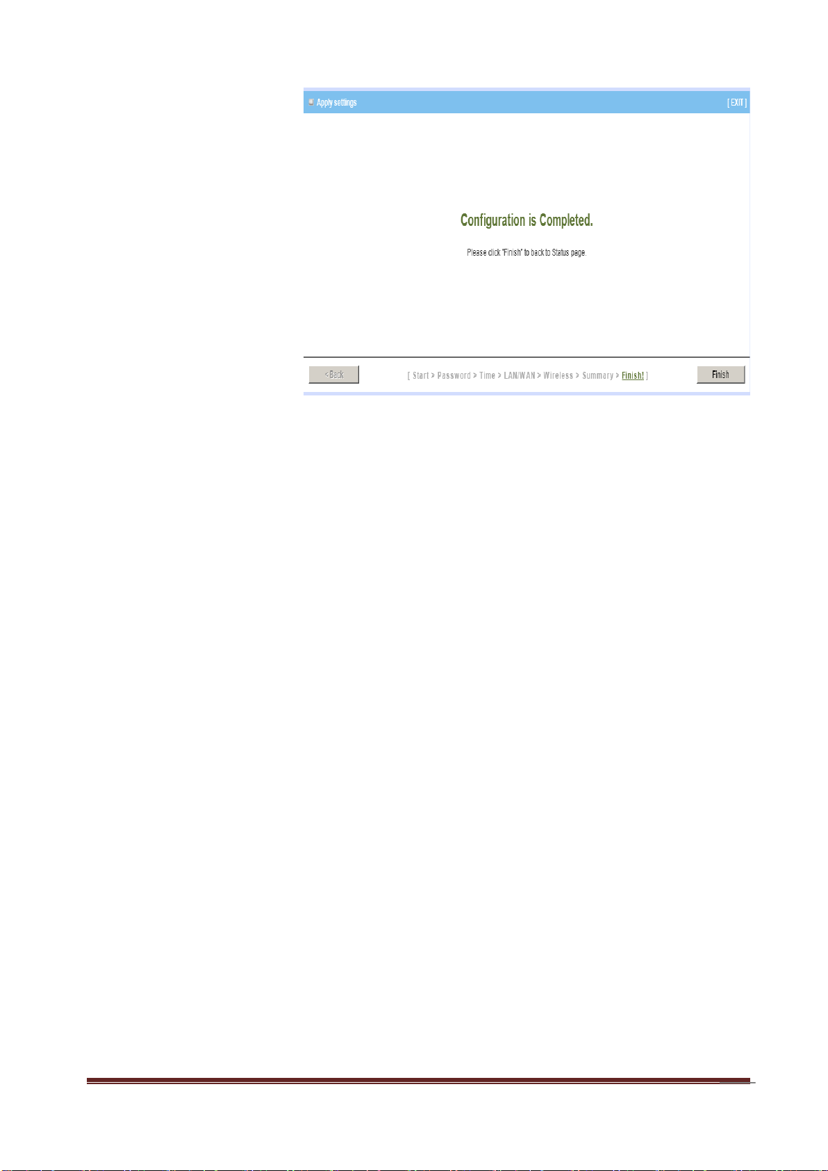
Step 9:
Click Finish to complete
it.
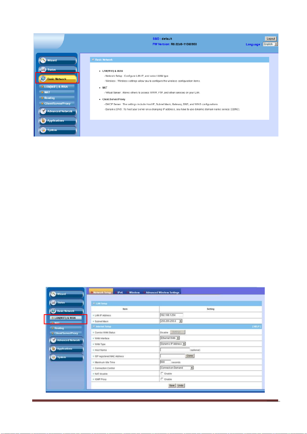
Chapter 3 Configurations- Basic Network
You can do Basic Network settings in this section for (LAN(WiFi) & WAN, NAT, Routing
and Client/Server/Proxy as shown in the icon below.
A-LINK WNAP4G User Manual
Page 20
20
3.1 LAN(WiFi) & WAN Setup
Network Setup: Configure LAN IP and select WAN type
IPv6: six types of IPv6 setttings- Static IPv6/ DHCPv6/ PPPoE/ 6 to 4 / IPv6
in IPv4 tunnel/ RD6
Wireless: Wireless settings allow you to configure the wireless
configuration
items
Advanced Wireless Setting
A-LINK WNAP4G User Manual
Page 21
21
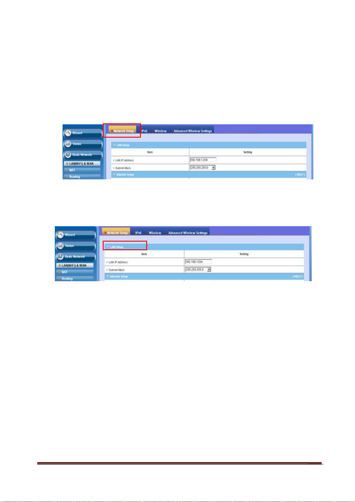
3.1.1 Network Setup
This router allows you to do LAN Setup and Internet Setup. Please see the
following instructions to do the necessary settings.
3.1.1.1 LAN Setup
1. LAN IP Address: The local IP address of this device. The computers on
your network must use the LAN IP address of this device as their Default
Gateway. You can change it if necessary.
2. Subnet Mask: Input your Subnet mask. (All devices in the network must
have the same subnet mask.) The default subnet mask is 255.255.255.0.
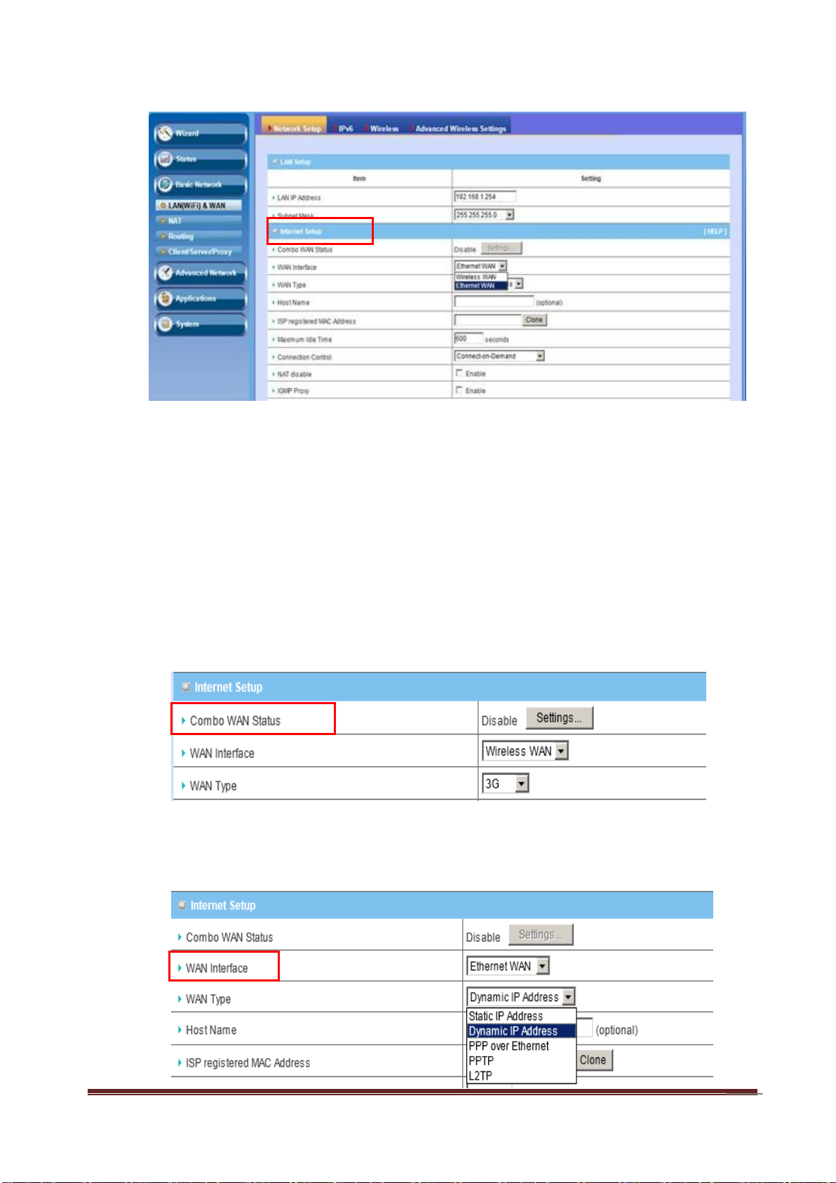
3.1.1.2 Internet Setup
This device is equipped with two WAN Interfaces to support different WAN Type
connections.
A-LINK WNAP4G User Manual
Page 22
22
1. Combo WAN Status
Display status of combo WAN. With Combo WAN feature, you can choose one
primary WAN connection, and set another WAN connection for backup.
Otherwise, you can also choose “Load Sharing” to use Ethernet WAN and 3G
WAN simultaneously. The combo WAN status will be showed here. Press
“Settings” button to configure this feature.
2. WAN Interface
Select Ethernet WAN or Wireless WAN to continue.
A-LINK WNAP4G User Manual
Page 23
23
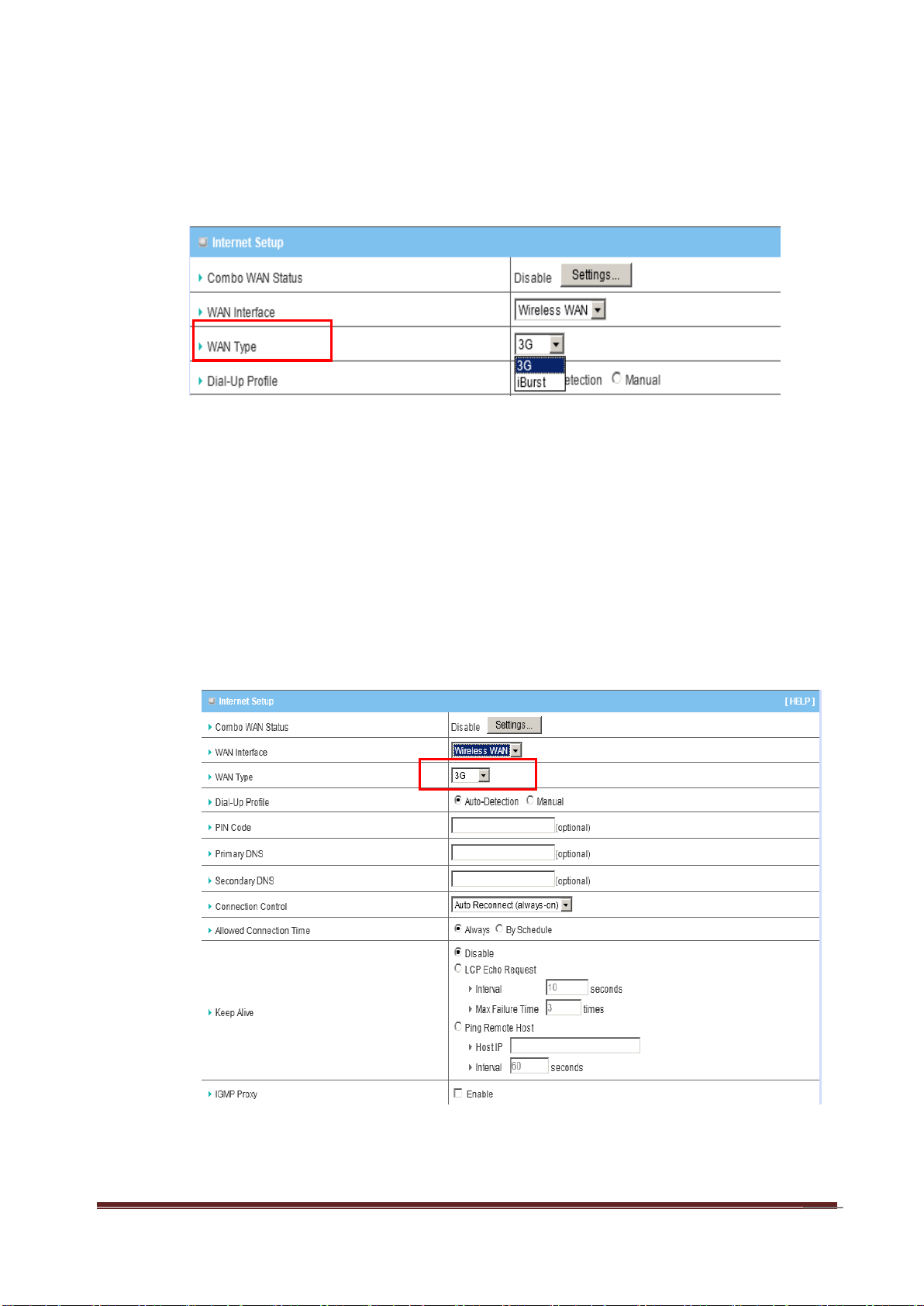
3. WAN Type
You can choose the correct WAN Type of 3G or iBurst from the following
options.
A. 3G
This device supports different WAN types of connection for users to connect to
remote wireless ISP, such as 3G (WCDMA, HSxPA, HSPA+, CDMA2000, EVDO, TD-SCDMA), iBurst, or Wi-Fi Hotspot.
Note: Users need to insert USB modem card for 3G WAN connections.
a. WAN Type: Choose 3G for WAN connection.
b. Dial-Up Profile: Please select Auto-Detection or Manual. You can choose
A-LINK WNAP4G User Manual
Page 24

24
“Auto-Detection”, and the router will try to detect and configure the required 3G
service settings automatically. Otherwise, you can select “Manual”, and
manually fill in the required 3G service settings provided by your carrier or ISP.
c. Country*: Select your country.
d. Telecom*: Select your telecom.
e. 3G Network*: Select the 3G network
f. APN*: APN information for your 3G data card. It will show a value after you
choose country and telecom. You can also change it manually.
g. PIN Code: Enter the PIN Code for your SIM card if required. (Optional)
h. Dialed Number*: It will show a value after you choose country and
telecom. You can also change it manually.
i. Account*: The user name for 3G connection. It will show a value after you
choose country and telecom. You can also change it manually.
j. Password*: The password for 3G connection. It will show a value after you
choose country and telecom. You can also change it manually.
k. Authentication*: Choose authentication of 3G connection. You can leave it
as “Auto” if you are not sure.
l. Primary DNS*: You can assign a Primary DNS server if required.
(Optional)
m. Secondary DNS*: You can assign a Secondary DNS server if required.
(Optional)
n. Connection Control: There are 3 options to start connection:
Auto Reconnect (Always-on): The device will always try to link to Internet.
Connect-on-demand: The device won’t try to connect to Internet until LAN
PCs or devices try to go to Internet. Once Internet connection is established,
this device will drop the connection if maximum idle time is reached.
A-LINK WNAP4G User Manual
Page 25

25
Manually: The device won’t try to connect to Internet until users press
“connect” button at Status page. Once Internet connection is established, this
device will drop the connection if maximum idle time is reached.
o. Allowed Connection Time: You can limit WAN connection in a period of
time if required.
p. Keep Alive: There are three options for keep alive feature as below.
Disable: Disable keep alive feature.
LCP Echo Request: The device will constantly send LCP packets for
keeping alive. Enter the time interval and the maximum failure count.
Ping Remote Host: Enter the Remote host IP address and the time interval
to send the ping packets for keeping alive.
q. NAT Disable: You can disable NAT feature if required.
r. IGMP Proxy: Enable this feature allows multicast stream (e.g. IPTV
stream) to pass-through this device.
Note: The items with * above are only available when choosing Manual for
Dial-up Profile.
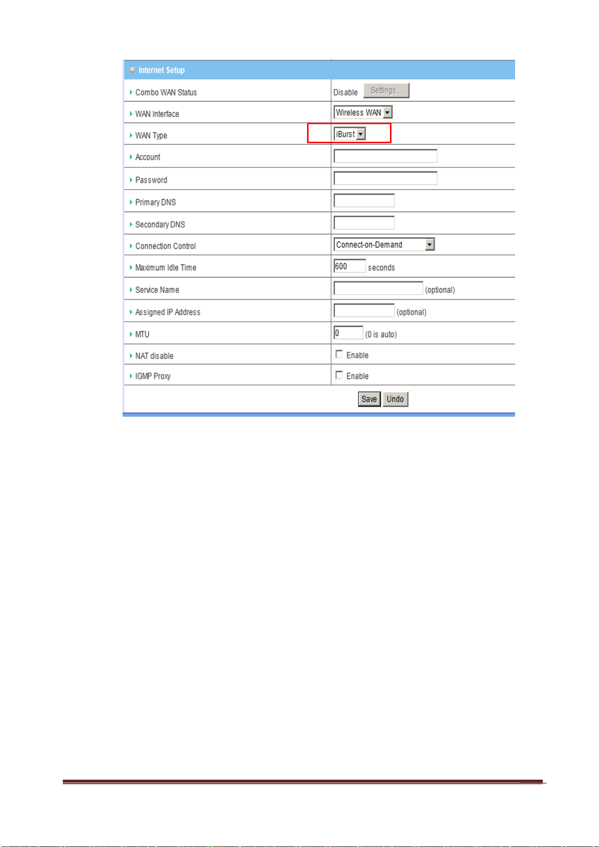
B. iBurst
Note: Users need to insert USB modem card for iBurst WAN connections.
A-LINK WNAP4G User Manual
Page 26
26
a. WAN Type: Choose iBurst for WAN connection.
b. Account: Enter the User Name for iBurst connection.
c. Password: Enter new Password for iBurst connection.
d. Primary DNS: You can assign a Primary DNS server if required. (Optional)
e. Secondary DNS: You can assign a Secondary DNS server if required.
(Optional)
f. Connection Control: There are 3 options to start connection:
Auto Reconnect (Always-on): The device will always try to link to Internet.
Connect-on-demand: The device won’t try to connect to Internet until LAN
PCs or devices try to go to Internet. Once Internet connection is established,
this device will drop the connection if maximum idle time is reached.
A-LINK WNAP4G User Manual
Page 27

27
Manually: The device won’t try to connect to Internet until users press
“connect” button at Status page. Once Internet connection is established, this
device will drop the connection if maximum idle time is reached.
g. Maximum Idle Time: The amount of time of inactivity before disconnecting
Internet connection. Set it to zero, or choosing “Auto-reconnect” mode to
disable this feature.
h. Service Name: Input the service name if your ISP requires it. (Optional)
i. Assigned IP Address: Input a IP address if your ISP requires it. (Optional)
j. Maximum Transmission Unit (MTU): You can change MTU value if
required. The default MTU value is set to 0 (auto).
k. NAT disable: You can disable NAT feature if required.
l. IGMP Proxy: Enable this feature allows multicast stream (e.g. IPTV
stream) to pass-through this device.
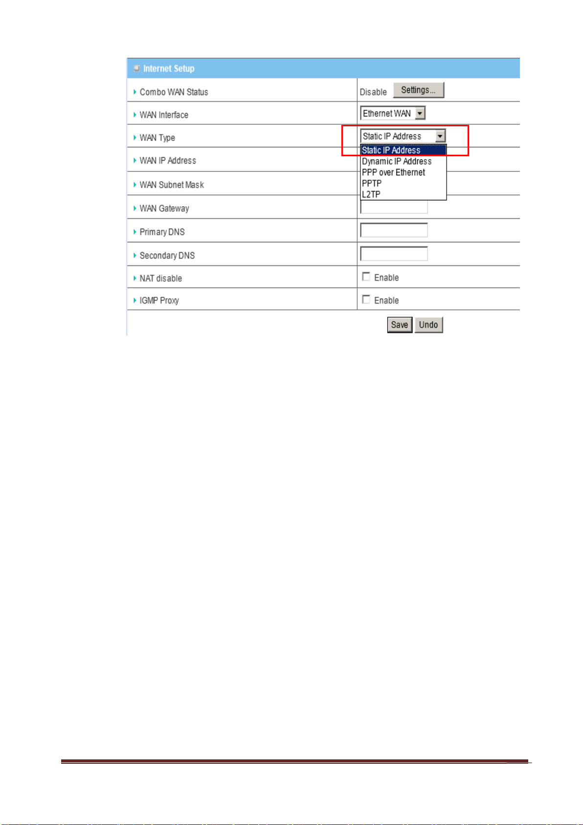
C. Static IP Address
A-LINK WNAP4G User Manual
Page 28
28
a. WAN Type: Choose Static IP Address.
b. WAN IP Address: Input the IP address you got from ISP.
c. Subnet Mask: Input the subnet mask of IP address you got from ISP.
d. WAN Gateway: Input the IP address of WAN gateway you got from ISP.
e. Primary DNS: Input the IP address of primary DNS you got from ISP.
f. Secondary DNS: Input the IP address of secondary DNS you got from ISP.
g. NAT disable: You can disable NAT feature if required.
h. IGMP Proxy: Enable this feature allows multicast stream (e.g. IPTV
stream) to pass-through this device.
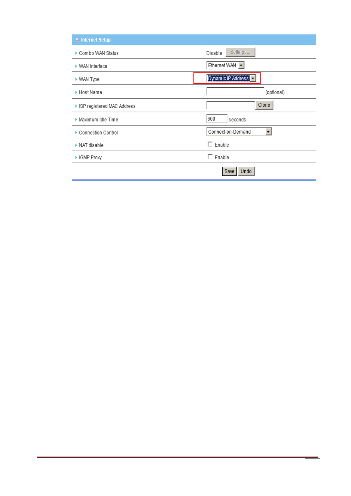
D. Dynamic IP Address
A-LINK WNAP4G User Manual
Page 29
29
a. WAN Type: Choose Dynamic IP Address.
b. Host Name: Optional, required by some ISPs, for example, @Home.
c. ISP registered MAC Address: Some ISP (Cable company) will record your
MAC address on PC. You can press “Clone” button to copy the MAC address
on your PC here, or you can input it manually.
d. Maximum Idle Time: The amount of time of inactivity before disconnecting
Internet connection. Set it to zero, or choosing “Auto-reconnect” mode to
disable this feature.
e. Connection Control: There are 3 options to start connection:
Auto Reconnect (Always-on): The device will always try to link to Internet.
Connect-on-demand: The device won’t try to connect to Internet until LAN
PCs or devices try to go to Internet. Once Internet connection is established,
this device will drop the connection if maximum idle time is reached.
Manually: The device won’t try to connect to Internet until users press
“connect” button at Status page. Once Internet connection is established, this
device will drop the connection if maximum idle time is reached.
f. NAT disable: You can disable NAT feature if required.
A-LINK WNAP4G User Manual
Page 30
30
g. IGMP Proxy: Enable this feature allows multicast stream (e.g. IPTV
stream) to pass-through this device.
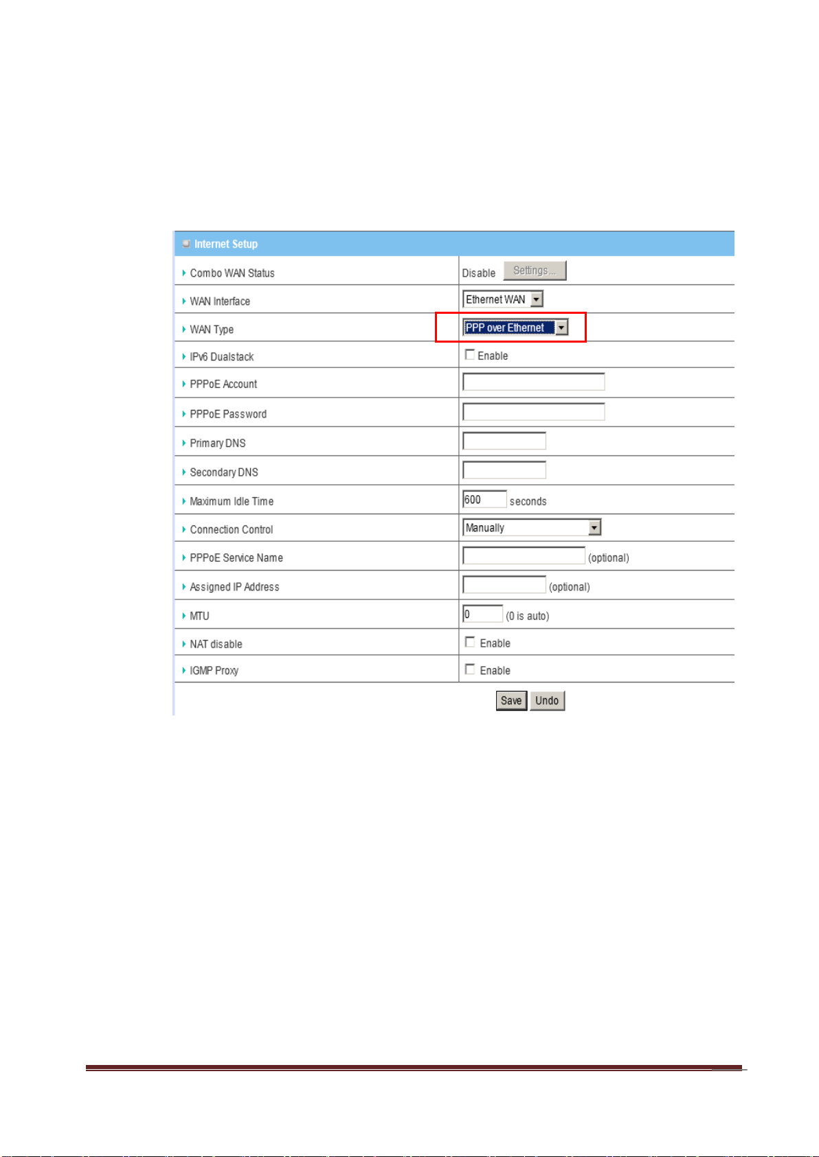
E. PPP over Ethernet
a. WAN Type: Choose PPP over Ethernet.
b. IPv6 Dual Stack: If your ISP supports IPv6 dual stack, you can check this
check box to get an IPv4 address and an IPv6 address via one PPPoE
connection. After you check this check box, you also need to enable IPv6
function at Advanced Setting->IPv6 setting page.
c. PPPoE Account and Password: The account and password your ISP
assigned to you.
d. Primary DNS: You can indicate IP address of primary DNS if required.
e. Secondary DNS: You can indicate IP address of secondary DNS if
A-LINK WNAP4G User Manual
Page 31

31
required.
f. Connection Control: There are 3 options to start connection:
Auto Reconnect (Always-on): The device will always try to link to Internet.
Connect-on-demand: The device won’t try to connect to Internet until LAN
PCs or devices try to go to Internet. Once Internet connection is established,
this device will drop the connection if maximum idle time is reached.
Manually: The device won’t try to connect to Internet until users press
“connect” button at Status page. Once Internet connection is established, this
device will drop the connection if maximum idle time is reached.
g. Maximum Idle Time: the amount of time of inactivity before disconnecting
your PPPoE session. Set it to zero or enable “Auto-reconnect” to disable this
feature.
h. PPPoE Service Name: Optional. Input the service name if your ISP
requires it.
i. Assigned IP Address: You can input a IP address if you got a fix IP
address from ISP.
j. Maximum Transmission Unit (MTU): Most ISP offers MTU value to users.
The default MTU value is 0 (auto).
k. NAT disable: You can disable NAT feature if required.
l. IGMP Proxy: Enable this feature allows multicast stream (e.g. IPTV
stream) to pass-through this device.
F. PPTP
A-LINK WNAP4G User Manual
Page 32

32
a. WAN Type: Choose PPTP.
b. IP Mode: You can select “Static IP Address” or “Dynamic IP Address”.
c. My IP Address*, My Subnet Mask*, and Gateway IP*: The IP address,
subnet mask, and IP address of gateway your ISP assigned to you.
d. Server IP Address/Name: The IP address of the PPTP server.
e. PPTP Account and Password: The account and password your ISP
assigned to you.
f. Connection ID: Optional. Input the connection ID if your ISP requires it.
g. Connection Control: There are 3 options to start connection:
Auto Reconnect (Always-on): The device will always try to link to Internet.
A-LINK WNAP4G User Manual
Page 33

33
Connect-on-demand: The device won’t try to connect to Internet until LAN
PCs or devices try to go to Internet. Once Internet connection is established,
this device will drop the connection if maximum idle time is reached.
Manually: The device won’t try to connect to Internet until users press
“connect” button at Status page. Once Internet connection is established, this
device will drop the connection if maximum idle time is reached.
h. Maximum Idle Time: the time of no activity to disconnect your PPTP
session. Set it to zero or enable “Auto-reconnect” to disable this feature.
i. Maximum Transmission Unit (MTU): Most ISP offers MTU value to users.
The default MTU value is 0 (auto).
j. IGMP Proxy: Enable this feature allows multicast stream (e.g. IPTV
stream) to pass-through this device.
Note: The items with * above are only available when choosing Static IP
Address in IP mode.
A-LINK WNAP4G User Manual
Page 34

34
G. L2TP
a. WAN Type: Choose L2TP.
b. IP Mode: You can select “Static IP Address” or “Dynamic IP Address”.
c. My IP Address*, My Subnet Mask*, and Gateway IP*: The IP address,
subnet mask, and IP address of gateway your ISP assigned to you.
d. Server IP Address/Name: The IP address of the L2TP server.
e. L2TP Account and Password: The account and password your ISP
assigned to you.
f. Connection ID: Optional. Input the connection ID if your ISP requires it.
g. Connection Control: There are 3 options to start connection:
Auto Reconnect (Always-on): The device will always try to link to Internet.
A-LINK WNAP4G User Manual
Page 35

35
Connect-on-demand: The device won’t try to connect to Internet until LAN
PCs or devices try to go to Internet. Once Internet connection is established,
this device will drop the connection if maximum idle time is reached.
Manually: The device won’t try to connect to Internet until users press
“connect” button at Status page. Once Internet connection is established, this
device will drop the connection if maximum idle time is reached.
h. Maximum Idle Time: the time of no activity to disconnect your L2TP
session. Set it to zero or enable “Auto-reconnect” to disable this feature.
i. Maximum Transmission Unit (MTU): Most ISP offers MTU value to users.
The default MTU value is 0 (auto).
j. IGMP Proxy: Enable this feature allows multicast stream (e.g. IPTV
stream) to pass-through this device.
Note. The items with * above are only available when choosing Static IP
Address in IP mode.
4. Combo WAN Setting
With Combo WAN feature, you can choose one primary WAN connection, and
set another WAN connection for backup. Otherwise, you can also choose
“Load Sharing” to use Ethernet WAN and 3G WAN simultaneously. The combo
WAN status will be showed at Internet Setup page. Press “Settings” button to
configure this feature.
A-LINK WNAP4G User Manual
Page 36

36
At Combo WAN setting page, you can choose Disable, Load Sharing, or
Failover options.
This Combo WAN feature will be deactivated if you select “Disable” from the
list.
A. Load Sharing
The feature of Load Sharing will activate 3G WAN and Ethernet WAN
simultaneously.
a. Combo WAN Mode: Choose Load Sharing mode.
b. Remote Host for Keep Alive: Type an IP address or domain name of
remote host to detect if Internet connection is alive.
c. Primary WAN: The primary WAN is the WAN type you set at Internet Setup
page.
d. Secondary WAN: Press “New Add” button to add the secondary WAN. If
the primary WAN is 3G or iBurst, then you can choose one of Static IP,
Dynamic IP, and PPPoE as the secondary WAN. However, 3G can be the
A-LINK WNAP4G User Manual
Page 37

37
secondary WAN if primary WAN is Static IP, Dynamic IP, or PPPoE.
B. Failover
With this function enabled, when the primary WAN connection is broken, the
device will automatically switch to secondary WAN connection and keep you
connected to Internet. Meanwhile, if the device detects that the primary WAN
connection is recovered, your Internet connection will be switched from
secondary WAN back to primary WAN.
a. Combo WAN Mode: Choose Failover mode.
b. Remote Host for Keep Alive: Type an IP address or domain name of
remote host to detect if Internet connection is alive.
c. Primary WAN: The primary WAN is the WAN type you set at Internet Setup
page.
d. Secondary WAN: Press “New Add” button to add the secondary WAN. If
A-LINK WNAP4G User Manual
Page 38

38
the primary WAN is 3G or iBurst, then you can choose one of Static IP,
Dynamic IP, and PPPoE as the secondary WAN. However, 3G can be the
secondary WAN if primary WAN is Static IP, Dynamic IP, or PPPoE.
3.1.2 IPv6
The growth of the Internet has created a need for more addresses than are possible
with IPv4. IPv6 (Internet Protocol version 6) is a version of the Internet Protocol
(IP) intended to succeed IPv4, which is the protocol currently used to direct almost
all Internet traffic. IPv6 also implements additional features not present in IPv4. It
simplifies aspects of address assignment (stateless address auto-configuration),
network renumbering and router announcements when changing Internet
connectivity providers. This router supports 6 types of IPv6 connection (Static IPv6/
DHCPv6/PPPoE/6 to 4/IPv6 in IPv4 tunnel/6RD). Please ask your ISP of what
types of IPv6 are supported before you proceed with IPv6 setup.
A-LINK WNAP4G User Manual
Page 39

39
3.1.2.1 Static IPv6
1. IPv6: Disable or enable the IPv6 functions.
2. IPv6 Connection: you can choose Static IPv6 from the list.
3. WAN IPv6 address settings: you can add IPv6 address / subnet prefix
length / default Gateway / Primary DNS address and secondary DNS address.
4. LAN IPv6 address settings: you can add LAN IPv6 address, and IPv6
Link-Local address will be showed automatically.
5. Address auto configuration setting: Disable or enable this auto
configuration setting. You may set stateless or stateful( Dynamic IPv6), and
also check if need to send Router advertisement messages periodically.
3.1.2.2 DHCPv6
1. IPv6 DNS settings: You may obtain IPv6 DNS automatically or set DNS
address manually for Primary DNS address and secondary DNS address.
2. LAN IPv6 address settings: You can add LAN IPv6 address, and IPv6
Link-Local address will be showed automatically.
3. Address auto configuration setting: Disable or enable this auto
configuration setting. You may set stateless or stateful( Dynamic IPv6), and
also check if need to send Router advertisement messages periodically.
A-LINK WNAP4G User Manual
Page 40

40
3.1.2.3 PPPoE
1. PPPoE settings: You need to type username and password of PPPoE
connection. The service name is only required when ISP asks you to input it.
MTU is 1492 by default.
2. LAN IPv6 address settings: You can add LAN IPv6 address, and IPv6
Link-Local address will be showed automatically.
3. Address auto configuration setting: Disable or enable this auto
configuration setting. You may set stateless or stateful( Dynamic IPv6), and
also check if need to send Router advertisement messages periodically.
3.1.2.4 When “6 to 4” is selected, you need to do the following settings.
1. 6 to 4 Settings: you may obtain IPv6 DNS automatically or set DNS
A-LINK WNAP4G User Manual
Page 41

41
address manually for Primary DNS address and secondary DNS address.
2. LAN IPv6 address settings: LAN IPv6 address and LAN IPv6 Link-Local
address.
3. Address auto configuration settings: Disable or enable this auto
configuration setting. You may set stateless or stateful (Dynamic IPv6), and
also check if need to send Router advertisement messages periodically.
3.1.2.5 When “IPv6 in IPv4 Tunnel” is selected you need to do the
following settings.
1 IPv6 in IPv4 Tunnel Settings: you may add remote / local IPv4 address
and local IPv6 address, then set DNS address manually for Primary DNS
address and secondary DNS address.
2 LAN IPv6 address setting: LAN IPv6 address and LAN IPv6 Link-Local
A-LINK WNAP4G User Manual
Page 42

42
address.
3 Address auto configuration setting: Disable or enable this auto
configuration setting. You may set stateless or stateful (Dynamic IPv6), and
also check if need to send Router advertisement messages periodically.
3.1.2.6 6RD
To set up this 6RD tunneling connection you will need to have the following
information from your IPv6 Internet Service Provider. If you do not have this
information, please contact your ISP. Remote IPv4 Address, IPv4 Mask Length,
Remote Prefix, Prefix Length, Primary DNS Address, and Secondary DNS
Address
A-LINK WNAP4G User Manual
Page 43

43
3.1.3 Wireless Settings
Wireless settings allow you to set the wireless configuration items.
1. Wireless Module: You can enable or disable wireless function.
2. Wireless Operation Mode: There are different wireless operation modes for
you to configure.
A. AP Router Mode: The device functions as a router and Access Point
simultaneously.
B. AP only Mode: The device functions as a pure access point.
C. WDS Hybrid Mode: The device can support WDS and AP mode
simultaneously.
D. WDS only Mode: The device can provides WDS point-to-point bridging,
A-LINK WNAP4G User Manual
Page 44

44
and point-to-multipoint bridging for deployment over large area. With the WDS
feature, the WLAN coverage range can be easily extended.
E. Lazy Mode: Lazy mode can auto-learning WDS peers without input other
AP's MAC address. Otherwise, you have to input the peer AP's MAC address
one by one to extend your wireless range.
F. Universal Repeater Mode: Universal Repeater is another technology used
to extend wireless coverage. It provides the function to act as Adapter (client) and
AP at the same time and can use this function to connect to a Root AP and use
AP (SSID name is the same as Root AP) function to service all wireless stations
within its coverage. All the stations within the coverage of this access point can
be bridged to the Root AP.
3. AP Number: Always keep “AP1” as the default.
4. Wireless Schedule: You can limit Wi-Fi functions in a period of time if required.
5. Network ID (SSID): Network ID is used for identifying the Wireless LAN
(WLAN). Client stations can roam freely over this device and other Access Points
that have the same Network ID. (The factory default setting is “default_2.4g”)
6. SSID Broadcast: The router will broadcast beacons that have some
information, including SSID so that wireless clients can know how many AP devices
by scanning the network. Therefore, if this setting is configured as “Disable”, the
wireless clients cannot find the device from beacons.
7. Channel: The radio channel number. The permissible channels depend on the
Regulatory Domain. The factory default setting is as follow: channel 1~11 for North
A-LINK WNAP4G User Manual
Page 45

45
America. (Channel 1~13 for European (ETSI); channel1~ 14 for Japan).
8. Wireless Mode: Choose “B/G mixed”, “B only”, “G only”, “N only”, “G/N mixed”
or “B/G/N mixed”. The factory default setting is “B/G/N mixed”.
9. Authentication mode: You may select one of authentication to secure your
wireless network: Open Shared, Auto, WPA-PSK, WPA, WPA2-PSK, WPA2, WPAPSK/WPA2-PSK, or WPA /WPA2.
A. Open
Open system authentication simply consists of two communications. The first is
an authentication request by the client that contains the station ID (typically the
MAC address). This is followed by an authentication response from the AP/router
containing a success or failure message. An example of when a failure may
occur is if the client's MAC address is explicitly excluded in the AP/router
configuration.
B. Shared
Shared key authentication relies on the fact that both stations taking part in the
authentication process have the same "shared" key or passphrase. The shared
key is manually set on both the client station and the AP/router. Three types of
shared key authentication are available today for home or small office WLAN
environments.
C. Auto
The AP will Select the Open or Shared by the client’s request automatically.
D. WPA-PSK
Select Encryption and Pre-share Key Mode
If you select HEX, you have to fill in 64 hexadecimal (0, 1, 2…8, 9, A, B…F)
digits. If you select ASCII, the length of pre-share key is from 8 to 63.
Fill in the key, Ex 12345678
A-LINK WNAP4G User Manual
Page 46

46
E. WPA
Check Box was used to switch the function of the WPA. When the WPA function
is enabled, the Wireless user must authenticate to this router first to use the
Network service. RADIUS Server IP address or the 802.1X server’s domainname.
Select Encryption and RADIUS Shared Key
If you select HEX, you have to fill in 64 hexadecimal (0, 1, 2…8, 9, A, B…F) digits
If you select ASCII, the length of pre-share key is from 8 to 63.
Key value shared by the RADIUS server and this router. This key value is
consistent with the key value in the RADIUS server.
F. WPA-PKS2
WPA-PSK2 user AES and TKIP for Same the encryption, the others are same the
WPA-PSK.
G. WPA2
Another encryption options for WPA-PSK-TKIP and WPA-PSK2-AES, the others
are same the WPA-PSK.
H. W PA/WPA2
Another encryption options for WPA-TKIP and WPA2-AES, the others are same
the WPA.
By pressing “WPS Setup”, you can configure and enable the easy setup feature
WPS (Wi-Fi Protection Setup) for your wireless network.
A-LINK WNAP4G User Manual
Page 47

47
1. WPS: You can enable this function by selecting “Enable”. WPS offers a safe and
easy way to allow the wireless clients connected to your wireless network.
2. AP PIN: You can press Generate New Pin to get an AP PIN.
3. Config Mode: Select your config Mode from “Registrar” or “Enrollee”.
4. Config Status: It shows the status of your configuration.
5. Config Method: You can select the Config Method here from “Pin Code” or
“Push Button”.
6. WPS status: According to your setting, the status will show “Start Process” or
“No used”
By selecting WDS Hybrid Mode, you can connect this device to another AP via
WDS connection.
A-LINK WNAP4G User Manual
Page 48

48
1. Wireless Module: You can enable this function by selecting “Enable”
2. Remote AP MAC 1~4: Enter the MAC address for remote AP that you want to
connect via WDS.
3. Encryption type: Select the appropriate category. Once you set up that type of
encryption, second LAN PC must enter the same encryption type as the first one.
Press “Wireless Clients List” and the list of wireless clients will be shown
consequently.
A-LINK WNAP4G User Manual
Page 49

49
3.1.4 Advanced Wireless Settings
Click on “Save” to store your settings or click “Undo” to give up the changes.
A-LINK WNAP4G User Manual
Page 50

50
3.2 NAT
Virtual Server: Allows others to access WWW.FTP. And other services on your
LAN.
Special Application: This configuration allows some applications to connect
and work with the NAT router.
Loopback: This option allows local hosts to access local virtual server via WAN
IP address of this router
DMZ: Allows a computer to be exposed to unrestricted 2-way communication for
Internet games, Video conferencing, Internet telephony and other special
applications.
.
3.2.1 Virtual Server
This product’s NAT firewall filters out unrecognized packets to protect your Intranet,
so all hosts behind this product are invisible to the outside world. If you wish, you
can make some of them accessible by enabling the Virtual Server Mapping.
A-LINK WNAP4G User Manual
Page 51

51
A virtual server is defined as a Service Port, and all requests to this port will be
redirected to the computer specified by the Server IP. Virtual Server can work with
Scheduling Rules, and give user more flexibility on Access control. For the details,
please refer to Scheduling Rule.
For example, if you have an FTP server (port 21) at 192.168.123.1, a Web server
(port 80) at 192.168.123.2, and a VPN server at 192.168.123.6, then you need to
specify the following virtual server mapping table:
Click on “Save” to store your settings or click “Undo” to give up the changes.
A-LINK WNAP4G User Manual
Page 52

52
3.2.2 Special AP
Some applications require multiple connections, like Internet games, Video
conferencing, Internet telephony, etc. Because of the firewall function, these
applications cannot work with a pure NAT router. The Special Applications feature
allows some of these applications to work with this product. If the mechanism of
Special Applications fails to make an application work, try setting your computer as
the DMZ host instead.
1. Trigger: The outbound port number issued by the application.
2. Incoming Ports: When the trigger packet is detected, the inbound packets
sent to the specified port numbers are allowed to pass through the firewall.
3. Enable: Check the checkbox to activate each of rule.
4. Use Rule#: you can set a schedule rule for each of rule.
This device provides some predefined settings. Select your application and click
“Copy to” to add the predefined setting to your list.
Click on “Save” to store your settings or click “Undo” to give up the changes.
A-LINK WNAP4G User Manual
Page 53

53
3.2.3 Loopback
With NAT Loopback enabled, you can access to the device using its WAN IP
Address or domain name from the LAN side, just like you are accessing it from the
internet. This function is helpful when there are some virtual servers operated under
this device, and you can easily access to these servers no matter where you are.
3.2.4 DMZ
1. DMZ Settings
DMZ (Demilitarized Zone) Host is a host without the protection of firewall. It
allows a computer to be exposed to unrestricted 2-way communication for
Internet games, Video conferencing, Internet telephony and other special
applications.
Click on “Save” to store your settings or click “Undo” to give up the changes.
A-LINK WNAP4G User Manual
Page 54

54
3.3 Routing
3.3.1 Static Routing
If you have more than one routers and subnets, you will need to enable routing
table to allow packets to find proper routing path and allow different subnets to
communicate with each other. The routing table allows you to determine which
physical interface addresses are utilized for outgoing IP data grams.
Static Routing: For static routing, you can specify up to 8 routing rules. You can
enter the destination IP address, subnet mask, gateway, and hop for each
routing rule, and then enable or disable the rule by checking or un-checking the
Enable checkbox
A-LINK WNAP4G User Manual
Page 55

55
3.3.2 Dynamic Routing
Dynamic Routing: Routing Information Protocol (RIP) will exchange information
about destinations for computing routes throughout the network. Please select
RIPv2 only if you have different subnets in your network. Otherwise, please select
RIPv1 if you need this protocol.
3.4 Client/Server/Proxy
DHCP Server: The settings include Host IP, Subnet Mask, Gateway, DNS, and
WINS configurations.
A-LINK WNAP4G User Manual
Page 56

56
Dynamic DNS: To host your server on a changing IP address, you have to use
dynamic domain name service (DDNS).
3.4.1 DHCP Server
1. DHCP Server: You can have total four (DHCP1~DHCP4) different settings
of DHCP server configurations on this device. If you divide LAN network into
different groups via VLAN ID (Please refer to Advanced Setting->VLAN for
detail), you can have different DHCP server settings for each of them.
2. IP Pool Starting/Ending Address: Whenever there is a request, the
DHCP server will automatically allocate an unused IP address from the IP
address pool to the requesting computer. You must specify the starting / ending
address of the IP address pool.
3. Lease Time: DHCP lease time to the DHCP client.
4. Domain Name: Optional, this information will be passed to the clients.
5. Primary DNS/Secondary DNS: Optional. This feature allows you to assign
a DNS Servers.
A-LINK WNAP4G User Manual
Page 57

57
6. Primary WINS/Secondary WINS: Optional. This feature allows you to
assign a WINS Servers
7. Gateway: Optional. Gateway Address would be the IP address of an
alternate gateway. This function enables you to assign another gateway to your
PC, when DHCP server offers an IP to your PC.
Click on “Save” to store your settings or click “Undo” to give up the changes.
Press “Clients List” and the list of DHCP clients will be shown consequently.
Press “Fixed Mapping” and the DHCP Server will reserve the special IP for
designated MAC address.
A-LINK WNAP4G User Manual
Page 58

58
3.4.2 Dynamic DNS
To host your server on a changing IP address, you have to use dynamic domain
name service (DDNS). So that anyone wishing to reach your host only needs to
know the name of it. Dynamic DNS will map the name of your host to your current
IP address, which changes each time you connect your Internet service provider.
Before you enable Dynamic DNS, you need to register an account on one of these
Dynamic DNS servers that we list in Provider field.
A-LINK WNAP4G User Manual
Page 59

59
Chapter 4 Configurations- Advanced Network
The Advanced Wireless Settings provide some 802.11 parameters for you to configure
and adjust the wireless behavior and performance. If you are not familiar with 802.11
technology, it is not recommended to change the default settings.
This router also support many advanced network features, such as firewall, QoS, VLAN
and Management. You can finish those configurations in this section.
4.1 Firewall
The firewall functions include Packet Filters, Domain Filters, URL Blocking, and MAC
Control.
A-LINK WNAP4G User Manual
Page 60

60
4.1.1 Firewall Status
This page shows the status of Firewall settings such as Packet Filters (for both
Outbound and Inbound Filters) and Domain Filters. You can do the settings by
clicking the Modify button on the right hand side or by going into the specific page
hereunder explained.
A-LINK WNAP4G User Manual
Page 61

61
4.1.2 Packet Filters
Packet Filter includes both outbound filter and inbound filter. And they have same
way to setting. It enables you to control what packets are allowed to pass the router.
Outbound filter applies on all outbound packets. However, inbound filter applies on
packets that destined to Virtual Servers or DMZ host only. You can select one of the
two filtering policies:
1. Allow all to pass except those match the specified rules.
2. Deny all to pass except those match the specified rules.
You can specify 8 rules for each direction: inbound or outbound. For each rule, you
can define the following:
Source IP address
Source port
Destination IP address
A-LINK WNAP4G User Manual
Page 62

62
Destination port
Protocol: TCP or UDP or both.
Use Rule#
For source or destination IP address, you can define a single IP address (4.3.2.1) or
a range of IP addresses (4.3.2.1-4.3.2.254). An empty implies all IP addresses.
For source or destination port, you can define a single port (80) or a range of ports
(1000-1999). Add prefix "T" or "U" to specify TCP or UDP protocol. For example,
T80, U53, U2000-2999, No prefix indicates both TCP and UDP are defined. An
empty implies all port addresses. Packet Filter can work with Scheduling Rules,
and give user more flexibility on Access control. For Detail, please refer to
Scheduling Rule.
Each rule can be enabled or disabled individually.
Afterwards, click on “Save” to store your settings or click “Undo” to give up the
changes.
A-LINK WNAP4G User Manual
Page 63

63
4.1.3 Domain Filters
Domain Filter prevents users under this device from accessing specific URLs.
1. Domain Filter: Check if you want to enable Domain Filter.
2. Log DNS Query: Check if you want to log the action when someone
accesses the specific URLs.
3. Privilege IP Address Range: Setting a group of hosts and privilege these
hosts to access network without restriction.
4. Domain Suffix: A suffix of URL can be restricted, for example, ".com",
"xxx.com".
5. Action: When someone is accessing the URL met the domain-suffix, what
kind of action you want.
Check “Drop” to block the access. Check “Log” to log these access.
A-LINK WNAP4G User Manual
Page 64

64
6. Enable: Check to enable each rule.
Afterwards, click on “Save” to store your settings or click “Undo” to give up
the changes.
4.1.4 URL Blocking
URL Blocking will block LAN computers to connect with pre-define Websites. The
major difference between “Domain filter” and “URL Blocking” is Domain filter
requires user to input suffix (like .com or .org, etc), while URL Blocking requires user
to input a keyword only. In other words, Domain filter can block specific website,
while URL Blocking can block hundreds of websites by simply a keyword.
1. URL Blocking: Check if you want to enable URL Blocking.
2. URL: If any part of the Website's URL matches the pre-defined word, the
connection will be blocked. For example, you can use pre-defined word "sex" to
A-LINK WNAP4G User Manual
Page 65

65
block all websites if their URLs contain pre-defined word "sex".
3. Enable: Check to enable each rule.
Afterwards, click on “Save” to store your settings or click “Undo” to give up
the changes.
4.1.5 MAC Control
MAC Address Control allows you to assign different access right for different users
and to assign a specific IP address to a certain MAC address.
1. MAC Address Control: Check “Enable” to enable the “MAC Address
Control”. All of the settings in this page will take effect only when “Enable” is
checked.
2. Connection control: Check "Connection control" to enable the controlling of
which wired and wireless clients can connect with this device. If a client is denied
A-LINK WNAP4G User Manual
Page 66

66
to connect with this device, it means the client can't access to the Internet either.
Choose "allow" or "deny" to allow or deny the clients, whose MAC addresses are
not in the "Control table" (please see below), to connect with this device.
3. Association control: Check "Association control" to enable the controlling of
which wireless client can associate to the wireless LAN. If a client is denied to
associate to the wireless LAN, it means the client can't send or receive any data
via this device. Choose "allow" or "deny" to allow or deny the clients, whose MAC
addresses are not in the "Control table", to associate to the wireless LAN.
Afterwards, click on “Save” to store your settings or click “Undo” to give up the
changes.
4.1.6 Others
1. MAC Address for Wake-on-LAN: Input MAC address of host that you want
to use WOL.
2. Discard PING from WAN side: When this feature is enabled, any host on
the WAN cannot ping this product.
3. DoS Attack Detection: When this feature is enabled, the router will detect
A-LINK WNAP4G User Manual
Page 67

67
and log the DoS attack coming from the Internet. Currently, the router can detect
the following DoS attack: SYN Attack, WinNuke, Port Scan, Ping of Death, Land
Attack etc.
4. SPI mode: You can enable this function and the router will check every
incoming packet to verify if this packet is valid or not, and drop those invalid
packets.
5. Disable PPTP passthrough: The PPTP passthrough is enabled by default.
You can disable here.
6. Disable L2TP passthrough: The L2TP passthrough is enabled by default.
You can disable here.
7. Disable IPSec passthrough: The IPSec passthrough is enabled by default.
You can disable here.
8. Stealth Mode: If enable this option, router will become “hidden” if someone
uses port scan utility to scan available ports on this router.
Afterwards, click on “Save” to store your settings or click “Undo” to give up
the changes.
4.2 QoS (Quality of Service)
Quality of Service (QoS) helps to prioritize data as it enters your router. By attaching
special identification marks or headers to incoming packets, QoS determines which
queue the packets enter, based on priority. This is useful when there are certain types of
data you want to give higher priority to, such as voice data packets given higher priority
than Web data packets.
This router provides two types of Cross-layer QoS (support throughout Application/
A-LINK WNAP4G User Manual
Page 68

68
Transport/ Data link/Network Layers in the network) tools. They are “Smart QoS” and
“User Defined Rule-based QoS” to help you easily configure the QoS that you need.
Please find more details in the later section.
The main goal of QoS is prioritizing incoming data, preventing data loss due to factors
such as jitter, delay and dropping. Another important aspect of QoS is ensuring that
prioritizing one data flow doesn’t interfere with other data flows. QoS can be toggled
Activated and Deactivated. QoS must be activated before you can edit the following
options. When you are done making changes, click on Save to save your changes.
4.2.1 Smart QoS
1. QoS : you can select enable/disable the QoS control
2. QoS Mode : select “Smart-QoS” for your own QoS control
3. Bandwidth of Upstream / Bandwidth of Downstream : you can input the
value of maximize of upstream and downstream bandwidth from your ISP
A-LINK WNAP4G User Manual
Page 69

69
4. Flexible Bandwidth Management (FBM):
A. When this management is enabled, system will share the bandwidth of those
selected applications to other applications if user do not run those selected
application, for example, If you select Game/ VoIP/ Video 3 applications for
higher priority in your system, then the system will automatically reserve 10% of
bandwidth to other application, and share the rest of bandwidth (100-
10)/3=30% each to Game/VoIP/Video, so if user do not play a game, then the
system will flexible share the 30% of bandwidth to other application.
Example for Smart-QoS with FBM enable : Mr. Wang selects Game/ VoIP/
Video 3 applications for higher priority in his system, the system will automatically
reserve 10% of minimum rate of bandwidth to other application, and share the
rest minimum rate of bandwidth (100-10)/3=30% each to Game/VoIP/Video. If
Mr. Wang’s son plays on-line game in the morning, the total bandwidth will all
reserve to his son. By the evening, when Mr. Wang back home and wants to
watch IPTV, then he will get the same priority with his son, and share the
bandwidth.
B. When this management is disabled, system will allow you to input percentage
of bandwidth manually.
A-LINK WNAP4G User Manual
Page 70

70
4.2.2 User Defined Rule-based QoS
1. QoS: You can enable/disable this QoS control.
2. QoS Mode: You can select User defined QoS rule for your own QoS control
3. Bandwidth of Upstream / Bandwidth of Downstream: You can input the
value of maximize of upstream and downstream bandwidth from your ISP
4. Create a QoS Rule: You can press the button of ‘Add New Rule’ shown in
the icon above to create a new QoS rule. you can enable the rule, and select
QoS class type as below. Please do “Class” selection before you do “Function”
selection. Each “Class” has its own subordinated “Function” options.
5. Add a Conjunction (AND) Rule: You can add a conjunction rule by clicking
the “Add a Conjunction (AND) Rule…” button and you will be able to see two
A-LINK WNAP4G User Manual
Page 71

71
more items- “And Rule - Class” and “And Rule – Class Info” in the icon below.
Class
Description
IP
IP address based
N
TCP port
UDPPORT
UDP port
MAC
MAC based
DSCP
DSCP based
TOS
TOS based
VLANPRI
VLAN enabled PRI
A. Class: You can create your own QoS rule by different classes as below.
A-LINK WNAP4G User Manual
DSCP setting: You can set your own DSCP value here.
Page 72

72
DiffServ Code Point: You can select code value.
Function
Description
Data
PRI
Priority
1~6
MAXR
Maximum bandwidth Rate
KBps/MBps
MINR
Minimum bandwidth Rate
KBps/MBps
SESSION
Connection session
number
DROP
Drop packet
None
LOG
Log event
None
ALERT
Alert event
None
Service Type: You can select their service type.
B. Function: You can set your own function value to enable your QoS rule as
below.
A-LINK WNAP4G User Manual
Page 73

73
Direction
IN
inbond
OUT
outbond
BOTH
inbond & outbond
PRI: Function data- Priority : 1~6
C. Direction: You can select inbond/ outbond for your direction.
D. Schedule: leave the default value of “(0)Always” as it is.
7. Finishing QoS settings:
A-LINK WNAP4G User Manual
Once you saved the QoS rule, system will show you the rule as below, you can
add another new rule accordingly.
Page 74

74
System will show you all your QoS rules as below
Note 1. : You can move up or down the priority of all rules by pointing the ‘↑’or ’↓’
if you want to change the priority.
Note 2. : You can unmark any rule if you do not want it enable now.
A-LINK WNAP4G User Manual
Page 75

75
4.3 VLAN
The VLAN function allows you to divide local network into different “virtual LAN”. In some
cases, ISP may need router to support “VLAN tag” for certain kinds of services (e.g.
IPTV) to work properly.
There are four LAN ports with this router, so you can have up to 4 VLAN if required.
Those four LAN ports belong to one VLAN by default. If you want to divide them into
different VLAN, you just need to assign different “VID” for them. If ISP requests a “VLAN
Tag” with your outgoing data, please remember to check the checkbox of “Tx TAG”.
If you want to map WAN ID, you can press “WAN VLAN settings”, and change router type
to Bridge and add WAN Map VLAN ID to your value.
A-LINK WNAP4G User Manual
Page 76

76
4.4 Green
The Smart Green Settings provide different power saving options for you to configure.
1. Green AP: With this function enabled, the device will try to turn off one wireless TX
path to save the power when there is no any wireless client connected.
2. Power Saving Mode & Power Saving Check Interval: With the power saving mode,
and time interval been specified, the device will automatically check if the power saving
criteria is meet or not periodically and reduce the overall power consumption of the
device consequently.
4.5 Management
4.5.1 UPnP
The device supports the UPnP function. If the OS of your client computer supports
this function, and you enabled it, like Windows XP, you can see the following icon
when the client computer gets IP from the device.
A-LINK WNAP4G User Manual
Page 77

77
4.5.2 SNMP
In brief, SNMP, the Simple Network Management Protocol, is a protocol designed to
give a user the capability to remotely manage a computer network by polling and
setting terminal values and monitoring network events.
1. Enable SNMP: You must check “Local”, “Remote” or both to enable SNMP
function. If “Local” is checked, this device will respond request from LAN. If
“Remote” is checked, this device will respond request from WAN.
A-LINK WNAP4G User Manual
Page 78

78
2. Get Community: The community of GetRequest is that this device will
respond.
3. Set Community: The community of SetRequest is that this device will
accept.
4. IP 1, IP 2, IP 3, IP 4: Enter the IP addresses of your SNMP Management
PCs. User has to configure where this device should send SNMP Trap message.
5. SNMP Version: Select proper SNMP Version that your SNMP Management
software supports.
6. WAN Access IP Address: If you want to limit the remote SNMP access to
specific computer, please enter the PC’s IP address. The default value is 0.0.0.0,
and it means that any Internet connected computer can get some information of
the device with SNMP protocol.
Afterwards, click on “Save” to store your settings or click “Undo” to give up the
changes.
A-LINK WNAP4G User Manual
Page 79

79
4.5.3 TR-069 Remote Management
1. TR-069: Disable or enable the TR-069 settings.
2. ACS setting: you may add ACS URL/ Username/ Password.
3. CPE setting: you may add CPE connection request port/ username
/password.
4. Inform setting: you may enable/disable the interval of informing CPE.
Note: TR-069 is a customized feature for ISP only and end user can not see this
setting page. If you are an ISP please contact with us once you get any problem to
configure.
A-LINK WNAP4G User Manual
Page 80

80
Chapter 5 Configurations - Applications
In this section you can do Disk Utility, Samba Server, FTP Service Configuration, Access
Control, iTunes Server, Download Assistant, and Web HDD settings.
5.1 USSD
USSD is a way to let subscribers finish some application on line, such as recharge SIM
card.
Enter the USSD command you got from ISP or carrier, and press button “Send” to send
this request to ISP or carrier. In most cases, ISP/Carrier will return a message regarding
to your USSD command. The replied message will be showed at this page as well.
Please note some replied message is sent back via SMS, and this device can’t deal with
any SMS message. If you don’t get any response after sending the command, please call
your ISP/carrier to confirm you request has been accepted.
A-LINK WNAP4G User Manual
Page 81

81
5.2 NAS
With NAS function on this device, you can share your USB drive or USB HDD via
network easily.
5.2.1 Disk Utility
1. Format
This utility would format the certain partition.
Please be noted! This action will clear all your data in this partition. You will not
be able to recover it any more.
2. Check
This utility could help you check the partition, find the lost files, try to fix some
problems.
A-LINK WNAP4G User Manual
Page 82

82
5.2.2 Samba Server
These settings are for Samba Server (Windows My Network Places).
1. Samba Server: Enable or Disable Samba server functions.
2. Computer Name
The name that is showed on the windows network neighbors search result.
3. WorkGroup
This name MUST be the same as your computer, or you could not search this
device via windows.
4. Server Comment: Just a comment for recognize.
5.2.3 FTP Server Configuration
A-LINK WNAP4G User Manual
Page 83

83
These settings are for FTP service.
1. FTP: Enable or disable functions of FTP server on this device.
2. FTP Port:
The default port is 21, but sometimes you might want to hide your FTP service by
changing it. We have the ability to receive the request on non-standard FTP port,
but please be noted, some NAT router could not support non-standard FTP port,
that means some of your clients might have to use passive mode to get file.
3. FTP Max Connection per IP: You can limit the maximum number of FTP
connection for each client.
4. FTP MAX Clients: You can indicate how many FTP clients can access the
FTP service on this device at the same time.
5. Client Support UTF8:
This option is used when your FTP client could support UTF8. Usually, the
default value “No” is okay for most clients.
5.2.4 Access Control
5.2.4.1 User Access Configuration
The default setting is “Guest mode”, all clients could access as anonymous
users.
If you want to control the permission, change to “Authorization mode” and save it,
then go to “User Configuration”.
A-LINK WNAP4G User Manual
Page 84

84
5.2.4.2 User Configuration
In this page, you can manage the user account.
Key in the user name and password then press “Add” could let you add a new
user.
If you want to delete an account, select it and click “Delete” button.
5.2.5 iTune Server
This function could enable the built-in iTunes Server to support iTunes which is a
media player released by Apple.
1. Server Name: The name of this server, it will be shown on the iTunes.
2. Share Partition: Select which partition on USB drive that you want to share.
3. Service Port: The TCP port for WEB management interface, for example, if
A-LINK WNAP4G User Manual
Page 85

85
the default value is 3689, then your iTunes server URL will be
http://This_Device_IP:3689
4. Access Password: The password for iTunes Server WEB management
interface.
5.2.6 Download Assistant
With Download Assistant, you don’t need to turn the computer all day on to wait for
download to be finished. This device will help you download files from remote FTP
server or HTTP server automatically
5.2.6.1 Download Assistant- FTP
If you want to download something from a FTP site regularly but you don’t want
to spend time on remembering doing this, this FTP download assistant could help
you.
1. Job Name:
A-LINK WNAP4G User Manual
Page 86

86
It’s for you to remember the job easily, and the device would use this name to
info you when the job is done.
2. URL:
The URL for the file you want to download.
You have to use this format:
IP/path/file, you don’t have to add protocol part such like “ftp://”.
3. Save To:
The destination path on USB disk that you want to save files.
Default value is /C/Download/FTP
4. Login method:
Anonymous, you can access this site without any authentication
Account, you have to enter the username and password to login.
5. Start Time:
Schedule: this device will start FTP download on the time that you specified. The
schedule job that is saved could be check on Status page by selecting “View
Scheduled Download Status”.
Note: The FTP download would be started immediately.
A-LINK WNAP4G User Manual
Page 87

87
5.2.6.2 HTTP
1. Job Name:
It’s for you to remember the job easily, and the device would use this name to
info you when the job is done.
2. URL:
The URL for the file you want to download.
You have to use this format:
IP/path/file, you don’t have to add protocol part such like “http://”.
3. Save To:
The destination path on USB disk that you want to save files.
Default value is /C/Download/HTTP
4. Start Time:
Schedule: this device will start FTP download on the time that you specified. The
schedule job that is saved could be check on Status page by selecting “View
Scheduled Download Status”.
A-LINK WNAP4G User Manual
Page 88

88
5.2.6.3 BT (Bit Torrent)
1. Start BT download
First, you have to get a seed file, which we called “torrent”. Then click the “Open”
link on UI, it would pop up a sub menu to let you upload.
Or, if your torrent file could be download from network, you could just enter a
URL.
2. BT download status- Job List
After you upload the torrent, download job would be started immediately.
The device could support 3 concurrent download jobs, other jobs would wait in
job queue. If one of the three running job is done, the next new job would be
started.
At this page, you could see the download process and the bandwidth.
A-LINK WNAP4G User Manual
Page 89

89
5.2.7 Download Status
Select any job on the list, and click right button of mouse, you could see a menu
with several actions you could do. You could “Pause”, “Delete” or “Remove” a job
with this sub menu.
5.2.8 Web HDD
This Web HDD can allow you to enter HDD by web UI, and also can allow you to let
‘guest’ to enter the ‘public’ area only.
A-LINK WNAP4G User Manual
Page 90

90
5.2.9 Miscellaneous
This setting is for UPnP AV media server service.
A-LINK WNAP4G User Manual
Page 91

91
Chapter 6 System
In this section you can see system information, system logs, use system tools for system
update and do service scheduling and system administration setting.
6.1 System Information
You can view the System Information and System log, and download/clear the System
A-LINK WNAP4G User Manual
Page 92

92
log, in this page.
6.2 System Status
6.2.1 Web Log
6.2.2 System Log
This page supports two methods to export system logs to specific destination by
means of syslog (UDP) and SMTP(TCP). The items you have to setup include:
1. IP Address for Syslog: Host IP of destination where syslog will be sent to.
Check Enable to enable this function.
A-LINK WNAP4G User Manual
Page 93

93
6.2.3 Email Alert
1. Setting of Email alert: Check if you want to enable Email alert (send syslog
via email).
2. SMTP Server: Port: Input the SMTP server IP and port, which are connected
with ':'. If you do not specify port number, the default value is 25.
For example, "mail.your_url.com" or "192.168.1.100:26".
3. SMTP Username: Enter the Username offered by your ISP.
4. SMTP Password: Enter the User name offered by your ISP.
5. E-mail Addresses: The recipients are the ones who will receive these logs.
You can assign more than 1 recipient, using ';' or ',' to separate these email
addresses.
6. E-mail Subject: The subject of email alert is optional.
Afterwards, click on “Save” to store your settings or click “Undo” to give up the
changes.
A-LINK WNAP4G User Manual
Page 94

94
6.3 System Tools
6.3.1 Account & Password
You can change the System Password here. We strongly recommend you to
change the system password for security reason. Click on “Save” to store your
settings or click “Undo” to give up the changes.
6.3.2 FW Upgrade
If new firmware is available, you can upgrade router firmware through the WEB GUI
here.
A-LINK WNAP4G User Manual
Page 95

95
Press “browse” button to indicate the file name of new firmware, and then press
Upgrade button to start to upgrade new firmware on this device. If you want to
upgrade a firmware which is from GPL policy, please check “Accept unofficial
firmware”.
NOTE: Please do not turn the device off when upgrade is processing.
6.3.3 System Time
1. Time Zone: Select a time zone where this device locates.
2. Auto-Synchronization: Check the “Enable” checkbox to enable this function.
Besides, you can select a NTP time server to consult UTC time.
3. Sync with Time Server: Click on the button if you want to set Date and Time
by NTP Protocol .
4. Sync with my PC: Click on the button if you want to set Date and Time using
PC’s Date and Time.
Afterwards, click on “Save” to store your settings or click “Undo” to give up
A-LINK WNAP4G User Manual
Page 96

96
the changes.
6.3.4 Others
In this section you can do system backup, reset to default, system reboot settings
and ping test.
6.3.4.1 Backup Settling
You can backup your settings by clicking the “Backup Setting” function item and
save it as a bin file. Once you want to restore these settings, please click
Firmware Upgrade button and use the bin file you saved.
A-LINK WNAP4G User Manual
Page 97

97
6.3.4.2 Reset to Default
You can also reset this device to factory default settings by clicking the” Reset to
default” function item.
6.3.4.3 Reboot
You can also reboot this device by clicking the “Reboot” function item.
6.3.4.4 Domain Name or IP Address for Ping Test
1. Domain Name or IP address for Ping Test allow you to configure an IP,
A-LINK WNAP4G User Manual
Page 98

98
and ping the device. You can ping a specific IP to test whether it is alive.
Afterwards, click on “Save” to store your settings or click “Undo” to give up
the changes.
6.4 Scheduling
You can set the schedule time to decide which service will be turned on or off. The added
rules will be listed and you can decide if you want to enable the set rules by checking or
un-checking the “Enable” box in the icon below.
Add New Rule: To create a schedule rule, click the “New Add” button or the “Add New
Rule…” button at the bottom in the icon above. When the next icon popped out you can
edit the Name of Rule, Policy, and set the schedule time (Week day, Start Time, and
End Time). The following example configures “wake-up time“ everyday from 06:00 to
07:00. Afterwards, click “save” to store your settings or click “Undo” to give up the
changes.
A-LINK WNAP4G User Manual
Page 99

99
6.5 MMI
You can set UI administration time-out duration give remote administration host port in
this page. When the host port is given please remember to check the enable box and
save your settings.
A-LINK WNAP4G User Manual
Page 100

100
Chapter 7 Troubleshooting
It is recommended that you
Ethernet connection to
configure it
This Chapter provides solutions to problems for the installation and operation of the
WNAP4G Router. You can refer to the following if you are having problems.
1 Why can’t I configure the router even the cable is plugged
and the LED is lit?
Do a Ping test to make sure that the WiFi
Note:
Broadband Router is responding.
Go to Start > Run.
use an
1. Type cmd.
2. Press OK.
3. Type ipconfig to get the IP of default gateway.
4. Type “ping 192.168.1.254”. Assure that you ping the correct IP Address
assigned to the WiFi Broadband Router. It will show four replies if you ping
correctly.
A-LINK WNAP4G User Manual
 Loading...