

Page 1

Rhein Tech Laboratories Client: Alinco, Inc.
360 Herndon Parkway Model: DJ-C7T
Suite 1400 Standards: FCC 15.121/IC RSS-215
Herndon, VA 20170 Report #: 2004067
http://www.rheintech.com
Date: April 22, 2004
APPENDIX H: MANUAL
Please see the following pages.
Page 25 of 50
Page 2
DJ-C7 T/E
Instruction Manual
Thank you for purchasing this ALINCO transceiver.
This instruction manual contains important safety and
operation instructions.
Please read it carefully before using the transceiver
and be sure to keep it for future reference.
VHF/UHF FM TRANSCEIVER
ALINCO, INC.
Page 3

NOTICE / Compliance Information Statement
This equipment has been tested and found to comply with the limits for a Class B digital device, pursuant to part 15 of the FCC Rules.
These limits are designed to provide reasonable protection against harmful interference in a residential installation.
This equipment generates, uses, and can radiate radio frequency energy and, if not installed and used in accordance with the instruction
manual, may cause harmful interference to radio communications. However, there is no guarantee that interference will not occur in a
particular installation. If this equipment does cause harmful interference to radio or television reception, which can be determined by turning
the equipment off and on, the user is encouraged to try to correct the interference by one or more of the following measures:
• Reorient or relocate the receiving antenna.
• Increase the separation between the equipment and receive.
• Connect the equipment into an outlet on a circuit different from that to which the receiver is connected.
• Consult the dealer or an experienced radio/TV technician for help.
Tested to Comply
With FCC Standards
FOR HOME OR OFFICE USE
Information in this document is subject to change without notice or obligation. All brand names and trademarks are the property of their
respective owners. Alinco cannot be liable for pictorial or typographical inaccuracies. Some parts, options and/or accessories are
unavailable in certain areas. Changes or modifications not expressly approved by the party responsible for compliance could void the user's
authority to operate the equipment.
VHF/UHF FM Transceiver DJ-C7 T/E
This device complies with Part 15 of the FCC Rules. Operation is subject to the following two conditions: (1) This device may not cause
harmful interference, and (2) this device must accept any interference received, including interference that may cause undesired operation.
Conformity Information
In case the unit you have purchased is marked with a CE symbol, a copy of relative conformity certificate or document can be reviewed at
http://www.alinco.com/usa.html.
Copyright © 2004 All rights reserved. No part of this document may be reproduced, copied, translated or transcribed in any from or by any
means without the prior written permission of Alinco. Inc., Osaka, Japan, English Edition Printed in Japan.
CE
FCC
2
Page 4

3
Before Operating the Transceiver.....................................
Attention .....................................................................................
Points to Note Before Transmitting.............................................
Points to Note When Using an External Power Supply ..............
1. Functions and Features.................................................
1.1 Standard Accessories ..........................................................
2. Accessories....................................................................
2.1 Attaching Accessories .........................................................
■Connecting and Disconnecting the Antenna ................
■Attaching and Detaching the Battery Pack ...................
■Prevent Short Circuiting the Battery Pack .....................
■Battery Recharger (AC Adapter)...................................
■Low Battery Indicator ....................................................
3. Control Function ............................................................
3.1 Name and Operation of the Transceiver Controls................
■Top and Front Views......................................................
■Side View.......................................................................
3.2 Keypad .................................................................................
3.3 Display..................................................................................
4. Basic Operations ...........................................................
4.1 Turning the Power ON ..........................................................
4.2 Adjusting the Audio Volume .................................................
4.3 Adjusting the Squelch ..........................................................
4.4 Operating Modes .................................................................
■Switching Between Modes ...........................................
4.5 VFO Mode ............................................................................
■Switching the Band .......................................................
■1MHz UP/DOWN ...........................................................
■Entry Completion Digit for Different Tuning Steps.........
4.6 Memory Mode ......................................................................
■Types of Memory...........................................................
■Programming a Memory Channel .................................
■Selecting a Memory Channel ........................................
■Clearing a Memory Channel..........................................
■Contents of Memory Channel........................................
4.7 Receiving..............................................................................
■Monitoring......................................................................
4.8 Transmitting..........................................................................
5. Advanced Operations....................................................
5.1 Scanning ..............................................................................
■VFO Scan ......................................................................
■Program Scan................................................................
■Memory Scan ................................................................
5.2 Keylock.................................................................................
5.3 Tone Burst ............................................................................
5.4 Priority...................................................................................
5.5 Tone Squelch and the Related Functions ............................
5.6 Tone Scan ............................................................................
5.7 Shift / Split Function..............................................................
6. Parameter Setting Mode ...............................................
6.1 Mode Setting Items ..............................................................
6.2 Selecting the Setting Mode ..................................................
6.3 Selecting the Parameters .....................................................
(1) Audio Volume Level ....................................................
(2) Antenna Type..............................................................
(3) Repeater function .......................................................
(4) Tone Burst Frequency ................................................
(5) APO (Auto Power Off) .................................................
(6) Battery Save function..................................................
(7) BEEP Sound................................................................
(8) BELL ...........................................................................
(9) Memory Write Protect function....................................
(10) Scan Type.................................................................
(11) AM / FM.....................................................................
Contents
Page 5

4
7. Cloning ...........................................................................
7.1 Cloning .................................................................................
■Connecting the Transceiver ..........................................
■Receiving the Master Data ............................................
■Transmitting Data from the Master Transceiver ............
8. Maintenance and Reference .........................................
8.1 Troubleshooting....................................................................
8.2 Resetting ..............................................................................
8.3 Options .................................................................................
8.4 Transmission System............................................................
9. Specifications ................................................................
Page 6
5
Before Operating the Transceiver
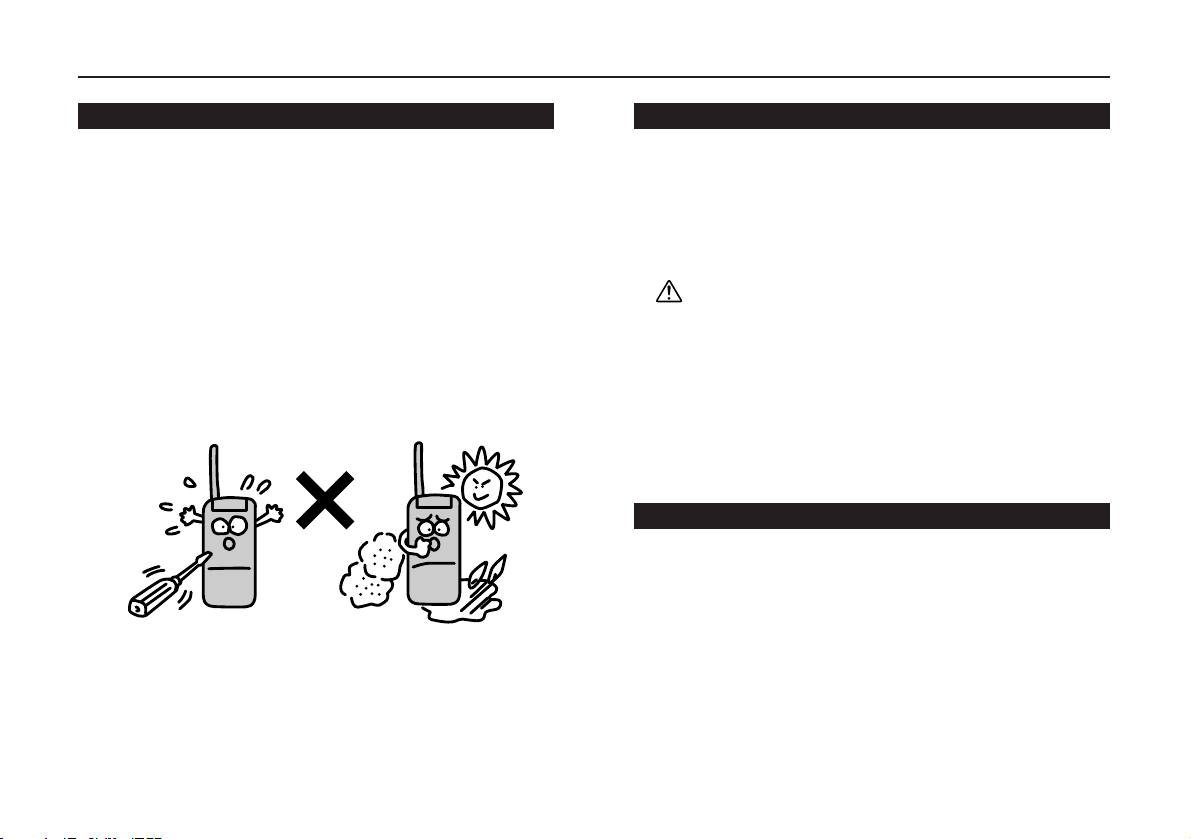
Attention
• Do not open the case or touch the interior components.
Tampering can cause equipment.
• Do not expose the transceiver to direct sunlight, dusty places
or place it near sources of heat.
• Keep the transceiver away from TVs, tuners or other
equipment if it interferes with reception.
• Securely connect the antenna included with the transceiver.
• When transmitting for a long time, the transceiver can
overheat.
• Turn the power off immediately if the transceiver emits smoke
or strange odors.
Ensure that the transceiver is safe, then bring it to the nearest
Alinco Service Center.
Points to Note Before Transmitting
Many wireless stations use frequency adjacent to the ham
bands for business purpose.
Be mindful when transmitting near them.
Even when amateur stations obey regulators, unexpected
interference can occur.
Pay sufficient attention during mobile operation.
Caution
The use of a transceiver in the following places should be
prohibited:
• Aboard aircraft
• In airport
• In shipping ports
• Within or near the operating area of business wireless
stations or their relay stations.
Before using in any of the above places, obtain any
necessary permissions from the proper authorities, and be
mindful of local laws that govern amateur radio operation.
Points to Note When Using an External Power Supply
• Use a regulated 3.7V - 6.0V DC external power supply.
• When connecting the power supply to the transceiver, use the
attachment AC adaptor for charge of battery (EDC-126).
• When power is supplied from cigarette socket of a car, use
the cigarette lighter cable for charge of battery (EDH-32).
• Turn the transceiver's power off when connecting or
disconnecting the DC cable.
Page 7
6
1
• 39 CTCSS tone squelch settings
• Tone burst function (1000,1450,1750 and 2100Hz)
• Split function
• Cloning
• Li-ion Battery adoption
1.1 Standard Accessories
• Li-ion Battery Pack EBP-58N (3.7V 600mAh)
• AC Adaptor for charge of battery (6.0V 0.5A)
• Helical Antenna
• Antenna Cap
• Instruction Manual
*Standard accessories may differ depending on the version.
2.1 Attaching the Accessories
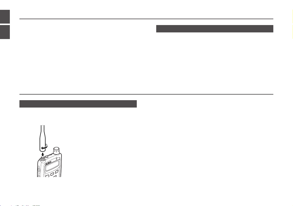
■Connecting and Disconnecting the Antenna
• Connecting
1.Connect the helical antenna
to the antenna connector at
the upper left corner.
2.Hold the helical antenna by
its base, and turn it clockwise
until it stops.
• Disconnecting
To disconnect the antenna, turn it counter-clockwise.
1. Functions and Features
2. Accessories
2
Functions and Features / Accessories
Page 8
7
2
Accessories
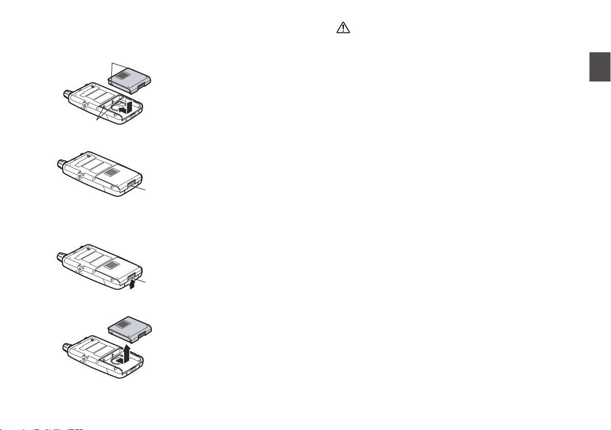
■Attaching and Detaching the Battery Pack
• Attaching
1.Align the projections on the
battery pack with the pits on
the transceiver.
2.Push in the direction of the
arrow until the latch clicks.
• Detaching
1.Push the latch upward.
2.Pull out the battery pack in
the direction of the arrow
shown left.
Caution
• The battery pack is not charged when shipped.
It must be charged before using.
• The battery pack can be charged by mounting it on the
DJ-C7 and connecting AC adaptor for charge of battery
to the DC power supply jack on the transceiver.
• It takes up to 2 hours and 30 minutes (maximum) to fully
charge the battery pack.
• Charging should be conducted within a temperature
range of 0 to 40˚C (32 to 104˚F).
• Do not modify, dismantle, incinerate, or immerse the
battery pack in water, as these practices can be
dangerous.
• Never short-circuit the battery pack terminals, as this can
cause damage to the equipment or lead to overheating
the battery, which could cause burns.
• Please be sure to remove the battery pack when the unit
is not in use.
• The battery pack should be stored in a dry place where
the temperature is from -20 to 45˚C (-4 to 113˚F).
• Typically, the battery pack can be charged up to 500
times.
However, the battery pack can be considered dead if the
period of use drops significantly despite the pack being
charged for the aforementioned charging time.
When this happens, a new pack should be used.
• In the interests of environmental protection, do not
dispose of the used battery pack improperly. Check with
your local solid waste officials for details on recycling
options or proper disposal in your area.
Latch
Latch
Projections
Pits
Page 9
8
2
Accessories
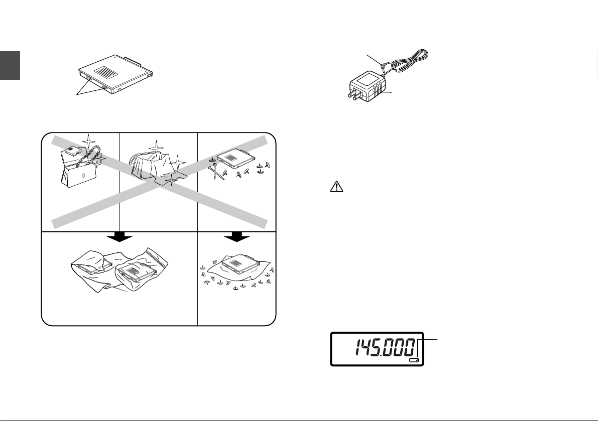
■Prevent Short Circuiting the Battery Pack
Be extra cautious when carrying
the battery pack; shortcircuiting will produce surge
current possibly resulting in fire.
■Battery Recharger (EDC-126)
• Recharging
1.Mount the battery pack on
the transceiver.
2.Connect AC adaptor plug to
the external power supply
jack on the transceiver.
3.Connect the power plug in an
outlet.
Regardless of whether the power of the transceiver is on or off,
it will start charging.
Low battery Indicator shown below blinks and TX/RX lamp
illuminates red during the charge with off status of the transceiver.
Once it will be full-charged, TX/RX lamp will turn green.
Caution
• Be sure to connect EDC-126 to the battery pack after
mounting it to the transceiver. Otherwise, the battery
pack won't be recharged.
• Disconnect EDC-126 from an outlet while not using it.
• Never charge the battery packs of other manufacturers
with this EDC-126 charger.
• The required charging time depends on the condition of
the battery pack.
• Never short-circuit the terminals of the battery pack with
metal objects and the like. Both this EDC-126 charger
and the transceiver should be damaged.
• The ECD-126 does not work when the voltage from an
outlet is extremely low.
■Low Battery Indicator
• Battery consumption level may change depending on the
surrounding temperature or the frequency of use.
• Charge the battery when the Low Battery Indicator appears.
• The Low Battery Indicator is not an indicator for battery left over.
Low Battery Indicator
The charge level is low.
AC adaptor plug
Power plug
Do enclose inside a non-conductive enclosure
(bags or handkerchief made only of nonconductive materials).
Protect by spreading
a non-conductive
sheet.
DON'T carry with
metals of any type,
e.g. chains.
DON'T carry the
battery pack inside
bags with metal
plated interior.
DON'T place in the
proximity of metals or
conductors,
e.g. nails, chains.
Terminals
Page 10
9
3
Control Function
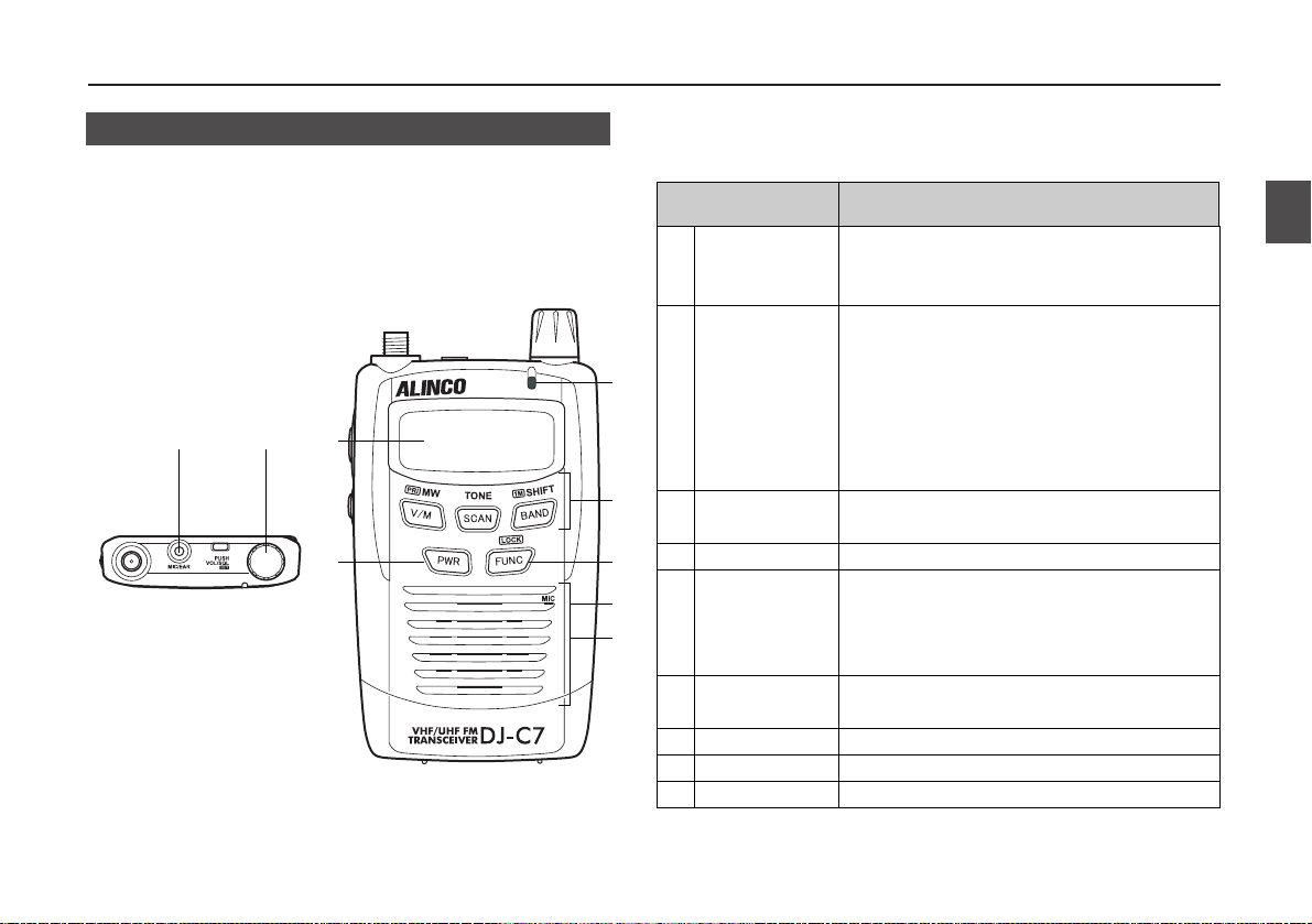
3.1 Name and Operation of the Transceiver Controls
■Top and Front Views
3. Control Function
12
7
3
4
9
8
1
2
3
4
5
6
7
8
9
SP/MIC
Connector
Dial
TX/RX Lamp
Keypad
FUNC Key
Microphone
Speaker
Power Key
Display (LCD)
Item Description
5
6
For connection of the optional external
speaker (8Ω) and microphone (2kΩ) with 2.5ø
stereo plug.
Rotate this dial to select transmitting /
receiving frequency, memory channel, and
other functions.
When you press it down, you can change the
volume and squelch level, or select options in
the Setting mode while the F icon appears.
(See on P.XX)
It illuminates green when the squelch
unmutes, red when transmitting.
It commands various operations. (See on P.XX)
Use this key in combination with other keys to
access various functions of the transceiver.
Holding this key for 1 second activates Key-
lock setting.
Speak into microphone from a distance of
Approx. 5 cm.
This is a thin built-in speaker.
Turn the power on/off.
Refer to "Display" in this manual. (See on P.XX)
Page 11
10
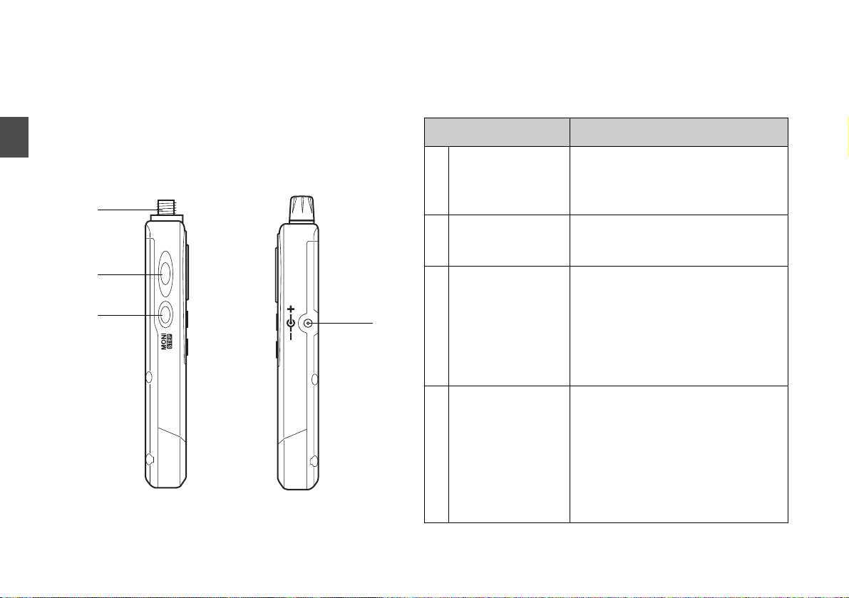
3
Control Function
10
11
12
13
SMA Antenna
Connector
PTT Key
MONI Key
DC-IN Jack
For connection of the included helical
antenna. If you use other antenna, choose
one with low SWR (Standing Wave Ratio)
designed for VHF and UHF frequencies.
Press this key to transmit. When the key
is released, the transceiver returns to a
receiving state.
When this key is pressed, the squelch is
unmuted and you can hear the received
signal. The squelch is also unmuted
when TSQ is set. (See on P.XX)
If this key is pressed while the F icon
appears, you can change a tuning step.
(See on P.XX)
This is for connecting an external power
supply.
By connecting included AC adaptor
(EDC-126), you can charge the battery.
By connecting an optional cigarette
lighter cable (EDH-32), you can supply
power from a car battery and charge the
battery.
Item Description
13
10
11
12
■Side View
Page 12
11
3
Control Function
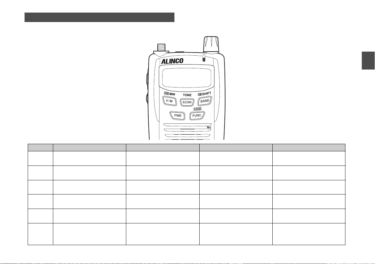
3.2 Keypad
Key
V/M
SCAN
BAND
FUNC
PWR
Dial
Independent Operation
Switches between VFO and
Memory mode. (See on P.XX)
Starts and stops scanning.
(See on P.XX)
Switches between bands.
(See on P.XX)
Switches between functions.
Turns power ON/OFF.
(See on P.XX)
Adjusts volume, squelch, and
other parameters/values.
(See on P.XX)
Press FUNC While F is ON
Programs to memory
channels. (See on P.XX)
Sets Tone Squelch setting.
(See on P.XX)
Sets Shift setting.
(See on P.XX)
Enters Setting mode.
(See on P.XX)
Press Key for 1 Sec
Starts Priority monitoring
function. (See on P.XX)
Switches ON/OFF of Keylock
function. (See on P.XX)
Dial Operation with Holding Key
Switches between Busy and
Timer scan. (See on P.XX)
Adjusts frequency in 1 MHz
unit. (See on P.XX)
Page 13

12
3
Control Function
3.3 Display
1
2
3
4
5
6
7
8
Appears when the key is pressed.
Appears when keys are locked.
Indicates the shift (+/-) direction or split
operation.
Appears when the tone squelch is set.
Appears when the bell function is on.
Indicates received signal level and the
transmission output.
Appears when the squelch is unmuted.
Indicates the frequency and status of various
settings.
9
10
11
12
13
14
15
16
Appears when the charge level is low.
Appears when the battery save function is on.
Appears when the auto power off function is
activated.
Appears when the reverse tone squelch is set.
Appears when the repeater mode is on.
Appears when the priority monitoring function is on.
Indicates memory channel No. and other setting
status.
Indicates the electric wave form.
Other icons which are not mentioned in the table are not used with the DJ-C7.
12 5
6
15
16
43
78910111214 13
Page 14

13
4
Basic Operations
4.1 Turning the Power ON
Hold the key down for a
second.
To turn the power OFF, hold the
key down until the display
disappears.
Caution
When you turn it on through the external power supply of a
voltage of over 6.5 volts, "dC-ovEr" is displayed on the
LCD with red and green LED alternately blinking. If so, pull
out the external power supply jack immediately from the
transceiver. When this status continues for a while, it will
be damaged.
Especially, note that none of warning signs are displayed
on the LCD when the external power supply exceeds over
6.5 volts with the ON status of the transceiver.
Application of a voltage of over 10 volts should break down
this transceiver.
Never use an AC adaptor and an AC adaptor cable of
other manufacturers other than the supplied.
4.2 Adjusting the Audio Volume
• There are 31 volume levels. (00-30)
• Default is set as 10.
1. Press the dial once.
will be displayed on the LCD indicating the present
volume level.
2. Adjust a volume level by rotating the dial.
As the value increases, the sound becomes louder.
3. Press the dial again or the PTT key to complete the
setting and to return to the normal.
It also returns to the normal when no dial operations continue
for 5 seconds.
Caution
When you use an earphone, be sure to set the volume to a
proper level. Besides, Audio Volume Level in the Setting
mode should be set as "LOW". For more information,
please refer to "Audio Volume Level" on P.XX.
4. Basic Operations
Page 15
14
4
Basic Operations
4.3 Adjusting the Squelch
The squelch is a function for eliminating noise which is
generated when none of the signals are monitored.
"To open squelch" means that the DJ-C7 monitors any of the
higher signals than the squelch level you set, and the receiving
sound will be heard.
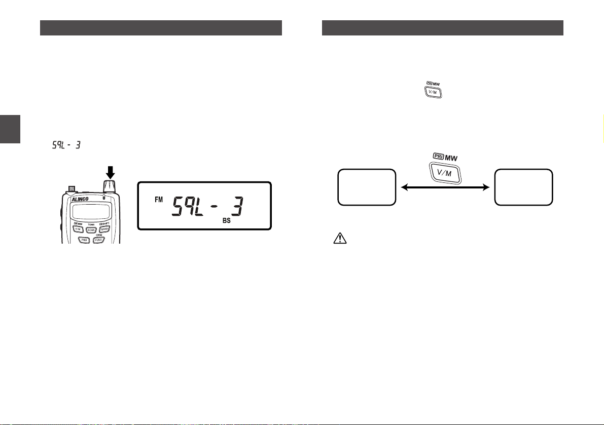
• There are 10 squelch levels. (0-9)
• Default is set as 3.
1. Press the dial twice.
will be displayed on the LCD indicating the present
squelch level.
2. Adjust a squelch level by rotating the dial.
When you set it to a higher level, insufficient (weak) signals
would be interrupted while monitoring or would not be
monitored at all.
Generally, you should set the squelch to the lowest level where
the noise would be cut off.
Depending on the frequencies and the radio wave
circumstances around you, the squelch level may need to be
adjusted.
3. Press the dial again or the PTT key to complete the
setting and to return to the normal.
It also returns to the normal when no dial operations continue
for 5 seconds.
4.4 Operating Modes
The DJ-C7 has two operating modes; VFO mode and Memory
(MR) mode.
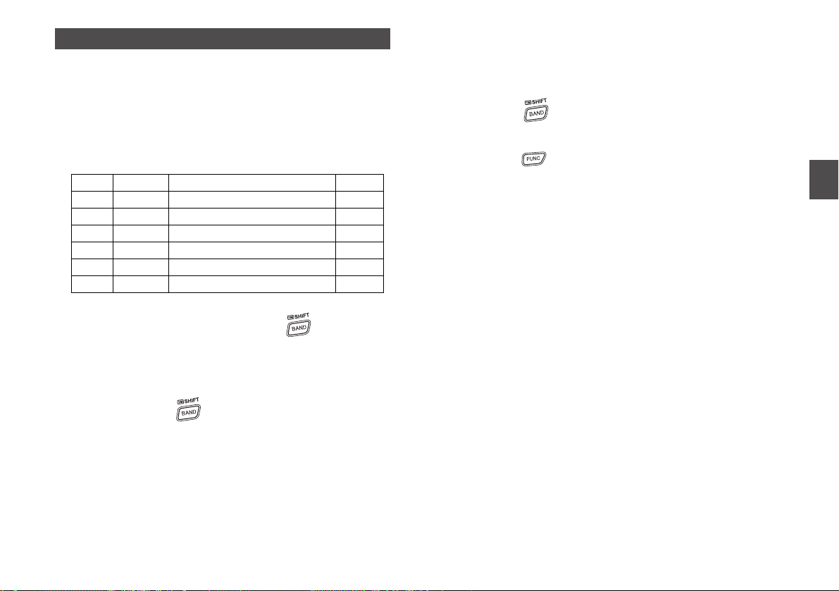
■Switching Between Modes
Everytime you press the key, the operating mode can be
switched between these two.
When you switch to the Memory mode, the memory number will
be displayed on the LED, however, nothing indicates in VFO
mode.
Caution
When nothing is programmed as memory channels, you
may not switch to the Memory mode.
MR mode
VFO mode
Page 16
15
4
Basic Operations
4.5 VFO Mode
This is a mode which is set as the factory-shipped
configuration.
Radio frequencies and various settings can be changed by
rotating the dial in this mode.
■Switching the Band
Everytime you press the BAND key, below 7 bands can be
switched in order.
■1 MHz UP/DOWN
When you rotate the dial with holding the key down, you
can increase or decrease a frequency by a 1MHz-step in
accordance with the direction of dial rotation.
This function is a quick way to increase or decrease the
frequency by a large amount.
After pressing the key, releasing it without any dial
operations can switch among bands.
■Entry Completion Digit for Different Tuning Steps
Tuning step frequency can be changed. You may choose one
of the unit selections as follows;
Auto, 5, 6.25, 8.33, 10, 12.5, 15, 20, 25, 30, 50, 100, 125, 200 kHz.
1. Press the key to select the band to be changed
its tuning step.
2. Press the key, and press the MONI key when you
see the F icon appears on the LED.
3. Rotate the dial to choose a tuning step frequency
mentioned above.
4. Press the PTT key to complete the setting and to
return to the frequency display.
The default tuning step is set as "Auto".
Choosing a tuning step but "Auto" in any of the bands releases
the default setting as "Auto" in all provided band selections.
And the last selection of the tuning step for a specified band is
programmed.
Returning the setting as "Auto" in a specified band, all tuning
steps for all provided bands will be returned as "Auto".
"Auto" uses tuning steps and modes which are both
programmed to the DJ-C7 in advance.
Default
VHF
L-UHF
H-UHF
AM Radio
Short Wave
FM Radio
Air
145.000(142.000~169.995MHz)
380.000(380.000~429.995MHz)
433.000(430.000~469.995MHz)
.531(531~1620kHz)
1.625(1.625~9.995MHz)
76.100(76.100~89.995MHz)
118.000(108.000~141.995MHz)
FM
FM
FM
AM
AM
WFM
AM/FM
Page 17
16
4
Basic Operations
4.6 Memory Mode
This mode allows you to program frequencies into the DJ-C7
memory. A programmed frequency is called as a channel.
The DJ-C7 has four types of memory functions; Memory
channel (general), Program scan channel, Priority channel, and
VFO auto programmed channel.
■Types of Memory
■Programming a Memory Channel
1. In VFO mode, adjust the frequency you want to
program by rotating the dial.
2. Set Shift (+/-) and/or Split settings, if necessary.
For more information on these settings, please refer to "Shift /
Split Functions" on P.XX.
3. Press the key to display memory channel number
on the LCD, and select a channel you want to write to
by rotating the dial.
The blank channels will blink and programmed channels will
stay lit up.
4. Press the key while the F icon appears on the
LCD.
A beep sounds telling that the frequency is written to the
memory channel successfully.
Tip
To overwrite to an already-exist memory channel, be sure
that Memory Write Protect function is set as "OFF". For
more information on this function, please refer to "Memory
Write Protect function" on P.XX.
■Selecting a Memory Channel
1. Press the key to switch to the Memory mode.
A memory channel number will be displayed on the LCD.
Caution
When nothing is written as a memory channel, you may
not switch to the Memory mode.
2. Rotate the dial to select the memory channel number
you want to call up.
Clockwise rotation: Each click increases the memory
channel number by one.
Counter-clockwise rotation: Each click decreases the memory
channel number by one.
Memory channel
(general)
(0-199)
Program scan
channel
(OA, Ob-4A, 4b)
Priority channel
(PRI)
VFO auto
programmed
channel
(AH, AL)
This is a channel which is called up in
Memory mode. You may program up to 200
channels in the DJ-C7. When you program
frequently used frequencies in advance, you
can easily call up whatever you want to use.
This is a channel which is used for Program
scanning function. You can program up to 5
pairs of frequency ranges. (higher and lower
limits) (See on P.XX)
This is a channel which is used for Priority
monitoring function. (See on P.XX)
This is a channel which is used for Repeater
function. (See on P.XX) You can program a pair
of frequency range (higher and lower limit) to
apply settings for the repeater automatically.
Page 18

17
4
Basic Operations
■Clearing a Memory Channel
1. Set Memory Write Protect function to "OFF" state, if
necessary.
For more information on this function, please refer to "Memory
Write Protect function" on P.XX.
2. Press the key to switch to the Memory mode.
3. Rotete the dial to select the memory channel number
you want to delete.
4. Press the key, and press the key while the
F icon appears on the LCD.
A beep sounds telling that the frequency is deleted
successfully, and "------" is displayed on the LCD.
5. With "------" displayed on the LCD, rotate the dial to
return to the Memory mode.
Press the key to return to the VFO mode.
When nothing is written as a memory channel, press the
key to return to the VFO mode.
Tip
Right after deleting the memory channel with "------"
displayed on the LCD, you can resume what you erased.
To restore the channel, press the key and press the
key again while the F icon appears on the LCD.
Note that you won't be able to restore it once you change
the operating mode.
■Contents of Memory Channel
The following settings can be stored in each memory channel.
• Frequency
• Shift frequency
• Shift direction (+/-) and Split setting
• Tone encoder frequency
• Tone decoder frequency
• Tone encoder/decoder setting
• Radio wave type (AM/FM)
Page 19

18
4
Basic Operations
4.7 Receiving
1. Adjust a volume level. (See on P.XX)
2. Adjust a squelch level. (See on P.XX)
3. Select a frequency on which you want to receive
signals.
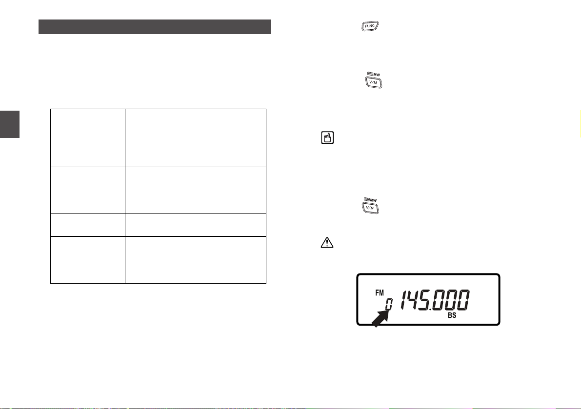
When a signal is received on the frequency you selected, the
BUSY icon will appear at the lower right on the LCD, and signal
level indicators are displayed according to the received
signals, as well.
Also, the green TX/RX indicator will light at the time.
■Monitoring
This function can be used to temporarily release the squelch
level setting you set only when the received signal is too
insufficient (weak) to monitor or is interrupted during
monitoring.
• The squelch is unmuted (is opened completely) while the
MONI key is held down, regardless of the squelch level
setting.
• This function unmutes (opens completely) the squelch even
Tone Squelch function is set.
4.8 Transmitting
1. Select a frequency on which you want to transmit
signals.
2. Press the PTT key.
When the red TX/RX indicator lights, it is now ready for
transmitting.
3. While holding the PTT key down, speak toward the
microphone on the transceiver at normal speaking
volume.
4. Release the PTT key when you finish speaking.
It returns to a receiving or monitoring state.
Caution
• Pressing the PTT key outside the transmission frequency
range displays " " on the LCD. Transmission is not
possible in this state.
• Especially, note that a receiving and a transmitting
frequency range differs when you set Shift direction
and/or Split setting.
Tip
Transmission available frequency ranges:
VHF... 144.000-147.995 MHz (DJ-C7T)
144.000-145.995 MHz (DJ-C7E)
UHF... 420.000-449.995 MHz (DJ-C7T)
430.000-439.995 MHz (DJ-C7E)
Page 20

19
5
Advanced Operations
5-1 Scanning
This function automatically detects receiving frequencies to
help you locate the signal that you want to receive.
There are two types of scanning; Busy scan and Timer scan.
The default is set as Busy ("bUSY") scan.
Switching between those two types can be done in the Setting
mode. (See on P.XX)
Busy scan:
If no signal is monitored after scanning stops, it will detect the
next frequency.
Timer scan:
Even if a signal is detected after scanning stops, it will switch to
the next frequency after a lapse of 5 seconds.
• While it is under scanning, the decimal point (.) on the LCD blinks.
• Even it is under scanning, a scan will be suspended and a
squelch will open temporarily when you hold the MONI key down.
Scanning will be continued when you release the MONI key.
• While it is under scanning, a scanning direction can be
changed with a dial operation. Scanning starts in the direction
of the last dial operation. (up or down)
• Press any key other than the MONI key to stop scanning.
■VFO Scan
In VFO mode, scanning is performed to detect signals with the
tuning step unit you set in advance (see on P.XX) for any
frequencies in a specified band.
1. Press the key to switch to the VFO mode.
2. While holding the key down, rotate the dial to
display "vFo" on the LCD.
3. Release the key.
Scanning will be performed with the tuning step unit in the
direction of the last dial operation. (up or down)
4. Rotate the dial in the clockwise direction to make the
scanning take place in the UP direction.
Conversely, rotate the dial in the counter-clockwise
direction to make the scanning take place in the
DOWN direction.
5. Press any key other than the MONI key to stop
scanning.
■Program Scan
Scanning is performed to detect signals between a specified
range of frequencies. Both higher limit and lower limit of the
range need to be set in advance. Otherwise, the following
operations can't be done.
A programmed pair of frequency range (higher and lower limit)
is called as a "program scan channel". You can program up to
5 pairs of frequency ranges.
For more information on how to program, please refer to
"Programming a Memory Channel" on P.XX.
1. Press the key to switch to the VFO mode.
2. While holding the key down, rotate the dial to
select a program scan channel to be detected.
3. Release the key.
When you have selected A side, scanning will be performed in
the direction of side "b".
Conversely, when you have selected b side, scanning will be
performed in the direction of side "A".
5. Advanced Operations
Page 21
20
5
Advanced Operations
4. Rotate the dial in the clockwise direction to make the
scanning take place in the UP direction.
Conversely, rotate the dial in the counter-clockwise
direction to make the scanning take place in the
DOWN direction.
5. Press any key other than the MONI key to stop scanning.
■Memory Scan
Scanning is performed to detect signals among programmed
frequencies as the memory channels. Memory channels need
to be set in advance. Otherwise, the following operations can't
be done.
For more information on how to program, please refer to
"Programming a Memory Channel" on P.XX.
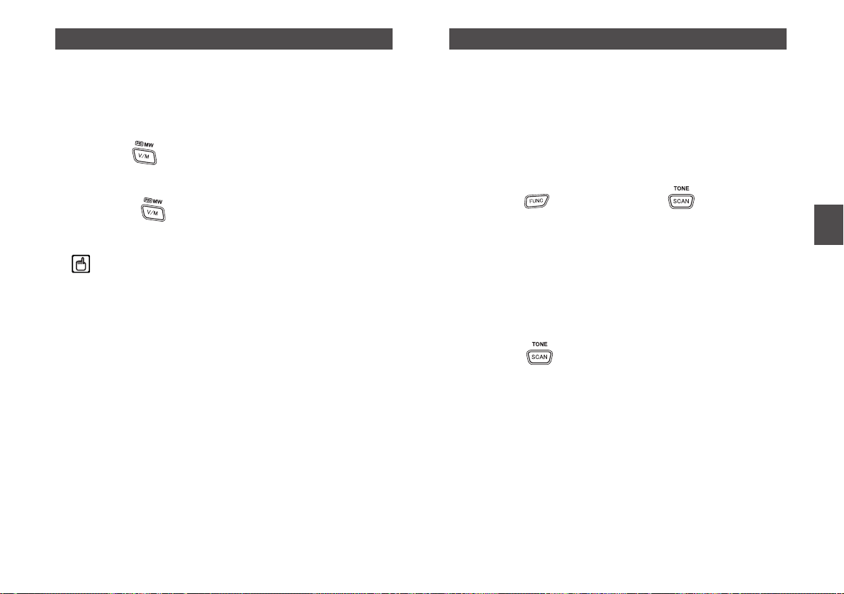
1. Press the key to switch to the Memory mode.
2. Press the key.
"mEmorY" is displayed on the LCD.
3. Release the key.
Scanning will be performed.
4. Rotate the dial in the clockwise direction to make the
scanning take place in the UP direction.
Conversely, rotate the dial in the counter-clockwise
direction to make the scanning take place in the
DOWN direction.
5. Press any key other than the MONI key to stop
scanning.
Tip
With the DJ-C7 either Memory Skip function, which is
excluded specified channels during a scan, or Memory
Bank function, which divides channels into several groups,
is NOT available.
5.2 Keylock
The keylock function avoids incorrect or unauthorized
operations to lock the keys.
The following can be done even the keylock function is ON.
• Receiving signals with the MONI key held down
• Transmitting with the PTT key held down
• Adjusting the volume and squelch level
• Turning the power ON/OFF
• Canceling the keylock
1. Hold the key for a second to switch ON/OFF the
keylock function.
When the keylock function is ON, the icon will appear on
the LCD.
5.3 Tone Burst
The Tone Burst function is used to call up another station or to
activate a repeater by adding a tone signal to the transmitted
signal.
• The tone signal is added while both the MONI key and the
PTT key are held down at the same time. The default
frequency of the tone signal is 1750Hz, and it can be
changed in the Setting mode. (See on P.XX)
• CTCSS Tone frequency is added and transmitted
automatically when a tone signal is set. You must select the
tone that matches the one monitored by the receiving station,
if that station is using a tone squelch. (See on P.XX)
Page 22
21
5.4 Priority
This function monitors two frequencies alternately to increase
efficiency for receiving signals.
Every 5 seconds, the DJ-C7 momentarily switches from a
specified frequency to the frequency which is programmed as
a priority channel (see on P.XX) for 0.5 seconds.
1. Hold the key down for a second to start the
Priority monitoring function.
The "PRI" icon will appear on the LCD.
2. Press the key while it is monitoring on the
specified frequency band to release this function.
Tip
• You are required to program a priority channel in
advance. Otherwise, a beep sounds and the above
operations can't be done. For more information on how to
program, please refer to "Programming a Memory
Channel" on P.XX.
• Scanning is not available during Priority monitoring
function.
• Even if a signal is received in the priority channel side, it
returns to the specified frequency band after a lapse of 5
seconds.
• You can specify a frequency in either VFO mode or one
of the memory channels (general).
5.5 Tone Squelch and the Related Functions
The Tone Squelch (The T and the SQ icons appear on the LCD
when it is set) is a function to unmute (open) squelch only when
one of the tone (encoder) frequency you set matches the tone
of another station.
Besides, when you set a decoder frequency and tell it to
another station, the station would easily catch your signals to
communicate with.
This function allows you to communicate with other stations
easily and quickly.
1. Press the key, and press the key while the F
icon appears on the LCD.
Both the T icon and a tone frequency are displayed on the
LCD. The tone encoder function is now ready to set.
2. Rotate the dial to adjust to a tone encoder frequency.
If you want to activate a repeater, press the PTT key or leave 5
seconds as it is to complete the setting. Also, go on to "Shift /
Split Function" on P.XX.
Otherwise, follow below steps.
3. Press the key while the tone encoder frequency
is displayed on the LCD.
The T icon, the SQ icon, and the programmed tone encoder
frequency are displayed on the LCD. The tone
encoder/decoder function (Tone Squelch) is now ready to set.
4. Rotate the dial to adjust to a tone decoder frequency.
It is possible to set a tone encoder and a tone decoder
frequency independently. You may set different frequencies
between an encoder and a decoder.
5. Press the PTT key or leave 5 seconds as it is to
complete the setting.
Tone Squelch function will be performed.
5
Advanced Operations
Page 23

22
5
Advanced Operations
6. Repeat steps from 1 to 4, and press the key in
the state of step 4.
After "XX" is displayed, press the key again to display
. With the OFF state, press the PTT key or leave 5 seconds
as it is to release the Tone Squelch function.
7. While "XX" is displayed on the LCD, press the PTT key
or leave 5 seconds as it is to perform the Reverse
Tone Squelch.
To release the Reverse Tone Squelch function, press the PTT
key or leave 5 seconds as it is while "XX" is displayed. is
displayed on the LCD indicating the function is now released.
The Reverse Tone Squelch ("XX" is displayed on the LCD when
it is set) is a function to mute (close) squelch only when the DJC7 receives frequency matched to the programmed encoder
frequency.
And it unmutes (opens) squelch when the DJ-C7 receives
frequency unmatched to the programmed encoder frequency.
This function is not generally used in ham radio. However, when
you set a tone which is used in wide-band communications
between range of 450 to 453 MHz and which continues to
transmit signals all the time, only a voice will be heard and a
grating noise will be cut off.
5.6 Tone Scan
This function detects tone frequencies automatically on a
receiving radio wave.
1. In VFO mode, rotate the dial to adjust to a frequency
on which a tone signal is transmitted.
2. While holding the key down, rotate the dial to
display "tonE" on the LCD.
3. Release the key.
Tone Scan function will be performed. Tone frequencies are
displayed on the LCD constantly.
Once the DJ-C7 finds a tone, a beep sounds and Tone Scan
function stops.
The found tone is programmed as a decoder frequency
automatically.
4. Press the key to return to the VFO mode.
This function continues searching a tone until it detects one.
Press the same key to quit or suspend temporarily.
5.7 Shift / Split Function
This function is usually used when you communicate via a
repeater station in ham radio.
Shift function:
It functions to shift a transmitting frequency from a receiving
frequency.
Split function:
It functions to receive signals in the VFO mode and to transmit
signals in the Memory mode, or vise versa.
1. Press the key. Everytime you press the key
while the F icon appears on the LCD, a display
indication will be changed as follows.
Caution
When a transmitting frequency turns to be the one on the
prohibited transmitting frequency band after the Shift / Split
function is set, " " is displayed on the LCD. If so, you
are not allowed to transmit any signals.
Shift frequency -> Shift frequency -> Shift frequency -> "SPLit"
"+" "-" "+/-"
Page 24

23
6
Parameter Setting Mode
6. Parameter Setting Mode
The DJ-C7's Setting mode is used to set the various operating
functions.
6.1 Mode Setting Items
(1) Audio Volume Level
(2) Antenna Type
(3) Repeater function
(4) Tone Burst Frequency
(5) APO (Auto Power Off)
(6) Battery Save function
(7) BEEP Sound
(8) BELL
(9) Memory Write Protect function
(10) Scan Type
(11) AM / FM
6.2 Selecting the Setting Mode
1. Press the key, and press the dial once while the
F icon appears on the LCD.
It switches to the Setting mode, and the item name will be
displayed on the LCD.
2. Select an item by pressing the dial.
Everytime you press the dial, the displayed item is changed by
turns.
When you press the MONI key, the items are displayed in
reverse direction.
3. When the item to be configured is displayed on the
LCD, change a value or a setting by rotating the dial.
4. Press the PTT key to complete the setting.
Page 25

24
6
Parameter Setting Mode
6.3 Selecting the Parameters
The following 11 functions can be set in the DJ-C7's Setting
mode.
(1) Audio Volume Level
When you use an earphone, you may reduce entire volume
level with this function if the volume is too loud.
1. " " is displayed on the LCD.
2. Rotate the dial to switch HIGH/LOW of the volume
level as follows.
Caution
Never change the setting while you are wearing the
earphone. Your ear may be hurt with extremely loud noise.
(2) Antenna Type
You can select an antenna according to a frequency you wish
to receive.
You may choose an antenna type from the following options.
Bar antenna: The internal antenna which receives the
AM radio band and the Short Wave. You
are not allowed to exchange it to the other
antenna. Any settings are not necessary to
use this antenna.
Earphone antenna: The earphone's cord performs a role of an
antenna. The earphone antenna only
receives the FM radio broadcasts.
External antenna: You are allowed to use the helical antenna
attached to the DJ-C7 or any antennas on
the market. The external antenna receives
all frequency bands over 10 MHz.
1. " " is displayed on the LCD.
2. Rotate the dial to select an antenna between Earphone
and External (SMA) as follows.
(3) Repeater function
With this function on, you may activate a repeater easily and
quickly.
1. " " is displayed on the LCD.
2. Rotate the dial to switch ON/OFF of Repeater function.
When you set ON, " " will appear on the LCD.
When you set "AH" and "AL" as a pair of VFO auto programmed
channel in the Memory mode, a tone frequency and a value of
the Shift setting are applied automatically when DJ-C7 receives
signals from that range.
(4) Tone Burst Frequency
1. "1750" is displayed on the LCD.
2. Rotate the dial to select Tone Burst Frequency setting
as follows.
"1750" -> "2100" -> "1000" -> "1450"
"SmA" -> "EAr"
"HivoLUmE" -> "LovoLUmE"
Page 26
25
6
Parameter Setting Mode
(5) APO (Auto Power Off)
This function automatically turns the power OFF if there is no
key operation for a specified period of time to prevent battery
charge wastage.
This is useful if you easily forget to turn off the transceiver.
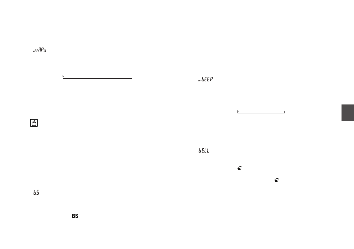
1. " " is displayed on the LCD.
2. Rotate the dial to select a setting value as follows.
Just before cutting the power OFF, a beep will be heard. Select
the time from 30, 60, 90 minutes, and OFF. When OFF is
selected, this function does not work.
To turn the power ON, press the POWER (PWR) key again.
Tip
With this function ON, even if the DJ-C7 receives signals, it
won't put off the turn-off period. Only key operations will
expand the period.
(6) Battery Save function
This function prevents battery charge wastage by switching the
reception circuit power supply OFF.
With this function ON, the transceiver will be a hibernation state
if there is no key operation or received signals for a continuous
period of 5 seconds.
1. " " is displayed on the LCD.
2. Rotate the dial to switch ON/OFF of Battery Save
function.
When you set ON, " " will appear on the LCD.
• The factory-shipped default is set as ON.
• This function will be released temporarily when the DJ-C7
receives signals or there is a key operation.
• This function will not be performed while the DJ-C7 is under
scanning.
• LCD displays even with the hibernation state.
(7) BEEP Sound
This function sounds a beep during operations. When you feel it
noisy or annoyed, you may turn off its sound.
1. " " is displayed on the LCD.
2. Rotate the dial to switch ON/OFF of BEEP Sound as
follows.
(8) BELL
It functions like a beeper. The DJ-C7 tells you with a bell sound
that another station calls up.
1. " " is displayed on the LCD.
2. Rotate the dial to switch ON/OFF of the bell function.
When you set ON, " " will appear on the LCD.
When the DJ-C7 receives signals, " " will blink on the LCD
and a bell sounds.
To release the bell sound, press the PTT key.
"oFF BEEP" -> "on BEEP"
"OFF" -> "30" -> "60" -> "90"
Page 27
26
6
Parameter Setting Mode
(9) Memory Write Protect function
This function prevents from overwriting or deleting memory
channels by mistake and protects what you've programmed.
You can always program frequencies to blank channels
regardless of this setting.
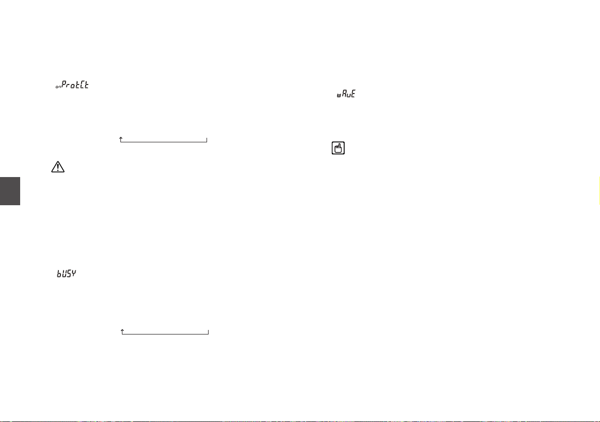
1. " " is displayed on the LCD.
2. Rotate the dial to switch ON/OFF of Memory Write
Protect function as follows.
Caution
Note that when you reset all settings (see on P.XX) with the
state of "oFFProtCt", which means allowing to overwrite,
ALL memory channels you programmed are deleted.
The factory-shipped default is set as "onProtCt" which
means preventing from overwriting.
(10) Scan Type
You can select a scan-resume condition between Busy scan
and Timer scan.
1. " " is displayed on the LCD.
2. Rotate the dial to switch a scan-resume condition as
follows.
(11) AM / FM
You can select a modulation mode between AM and FM.
It is necessary to switch a display for setting a tuning step in a
specified band in advance. For more information on this, please
refer to "Entry Completion Digit for Different Tuning Steps" on
P.XX.
1. " " is displayed on the LCD.
2. Rotate the dial to switch a scan-resume condition
between AM and FM.
Tip
When you set a tuning step as "Auto", you are not able to
switch a modulation mode. In the case, you will see "------"
displayed on the LCD.
"bUSY" -> "timEr"
"onProtCt" -> "oFFProtCt"
Page 28

30
7
Cloning
7.1 Cloning
With the Cloning function, it is possible to connect two
transceivers by a cable, and copy all settings from one unit
(call as a Master) to the other (call as a Slave).
This function transfers all master's settings including memory
channel data.
■Connecting the Transceiver
• Connect both of the speaker jacks on the sending transceiver
(Master side) and the receiving transceiver (Slave side) with a
ø 2.5 stereo mini-plug cord as shown in the below illustration.
• Be sure that both transceivers are switched OFF before
connecting them.
■Receiving the Master Data
Here are the operations of a slave transceiver side.
1. While holding the MONI key down, turn the power ON.
" " is displayed on the LCD, and the transceiver enters
the Clone mode.
2. Wait for a while until master data is transferred
completely.
For more information on sending the master data, please refer
to the next section.
3. Turn the power OFF on the slave's side.
• The stereo mini-plug cord should be a direct-coupled so that
it can avoid internal resistance.
• Even while the DJ-C7 transfers data, it can be suspended
with any key operations. To restart transferring, press the PTT
key.
• Do not disconnect the cable while cloning. When the cord is
disconnected, " " is displayed on the master's LCD, and
the DJ-C7 suspends transferring.
• All data in the slave side will be overwritten if cloning is
executed. Be careful with current data on the slave before
cloning.
■Transmitting Data from the Master Transceiver
Here are the operations of a master transceiver side.
1. While holding the MONI key down, turn the power ON.
" " is displayed on the LCD, and the master's transceiver
enters the Clone mode.
Master
To SP/MIC connector
on the transceiver
Slave
To SP/MIC connector
on the transceiver
7. Cloning
Page 29

31
7
Cloning
2. Press the dial.
" " is displayed on the LCD, and the master's
transceiver starts to transfer data.
" " is displayed on the LCD when transfer is completed
successfully.
3. Turn the power OFF on the master's side to release
the Clone mode.
If the DJ-C7 should fail to transfer data, " " is displayed on
the LCD. When you see the indicator, redo from step 1.
Page 30
32
8
Maintenance and Reference
8. Maintenance and Reference
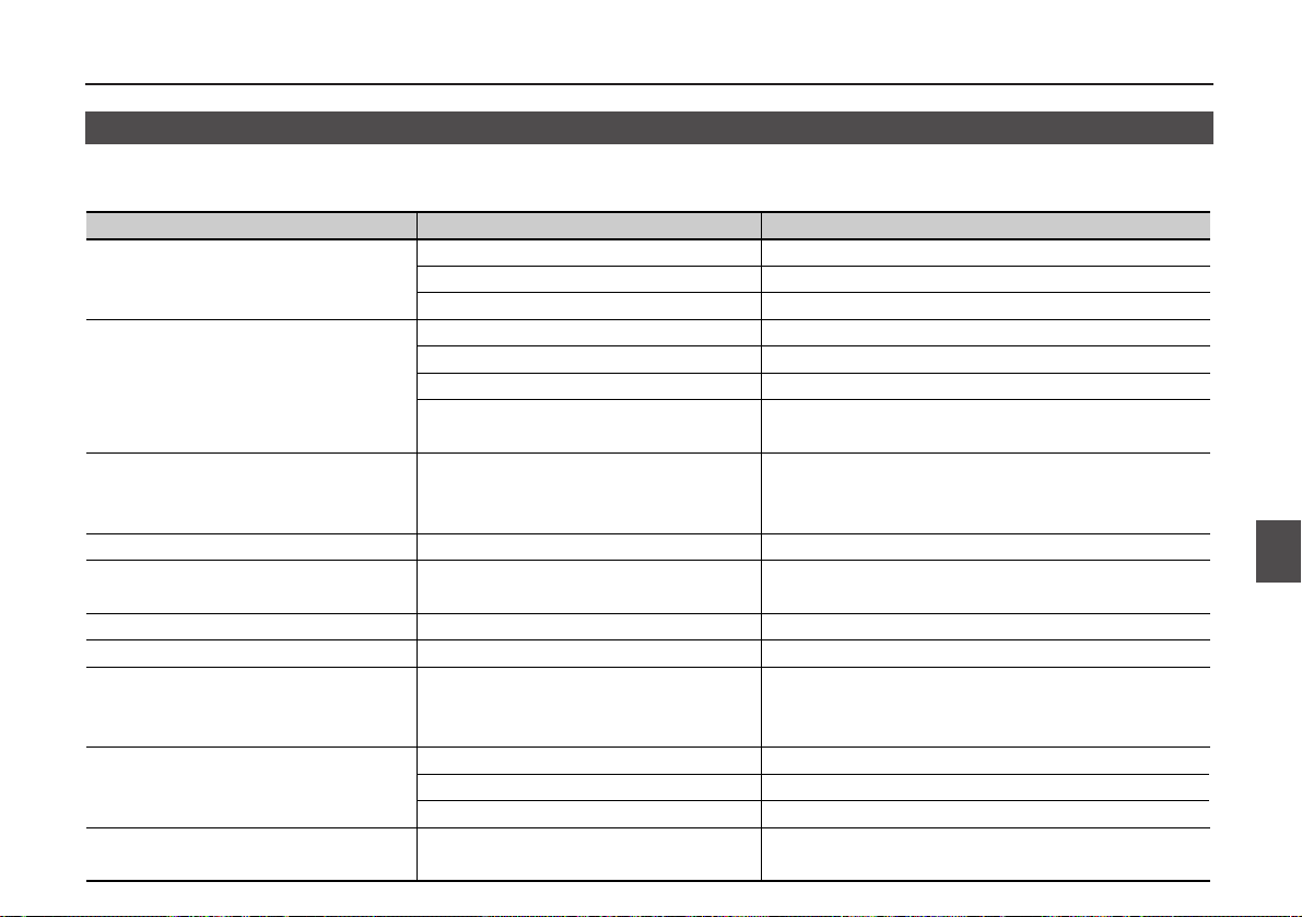
8.1 Troubleshooting
Please check the list below before concluding that the transceiver is faulty.
If a problem persists, reset the transceiver. This may correct erroneous operations.
Nothing appears on the display when
you turn the power on.
No speaker audio.
No reception.
Frequency display is incorrect.
Won't scan.
Frequency and memory number do not
change.
Key entry not possible.
One-touch repeater cannot be used.
Cannot transmit.
Display blinks or goes out when you
transmit.
Cannot transmit.
No reply when you transmit.
Display blinks or goes out when you
receive.
Poor Li-ion battery pack connection
Dead battery.
You are releasing the key too quickly.
Volume too low.
Squelch level too high.
Tone squelch is on.
You are pressing the PTT key and
transmitting.
CPU error.
Squelch is unmated.
Keylock is on.
Keylock is on.
Incorrect setting for one-touch repeater use.
Battery power is insufficient.
Not pressing the PTT key firmly enough.
You are outside of the band.( when shift is set.)
Incorrect frequency.
Battery power is insufficient.
Symptom Possible Cause Action
Check if the battery pack terminals are clean.
Recharge the battery pack.
Hold the power switch down for 1 second.
Adjust the volume.
Adjust the squelch.
Turn off tone squelch.
Release the PTT key.
Detach the battery pack or external power supply, wait
10 seconds and attach it again. If it is still not operation,
reset the transceiver.
Set squelch so that noise is just muted.
Turn off keylock.
Turn off keylock.
Set the transceiver correctly for repeater use.
Recharge the battery pack.
Press the PTT key firmly.
Transmit within transmission frequency range.
Match your frequency to receiving station's frequency.
Recharge the battery pack.
Page 31

33
8
Maintenance and Reference
8.2 Resetting
When you reset the transceiver, all settings are returned to the
initial (default) factory setting. You can reset programmed
channel memory when the write protect is off.
1. Press and hold the key and press the key
to turn the power on.
2. Release the keys when all icons are displayed.
The transceiver returns to the initial VFO mode.
●Factory Setting
• VFO Frequency VHF :145.000MHz
UHF :445.000MHz (T version)
UHF :433.000MHz (E version)
FM Radio :88.100MHz (T version)
FM Radio :87.500MHz (E version)
Air :118.000MHz (T version)
L-UHF :380.000MHz (T version)
• Memory Channel 0 - 199ch blank
• Audio Volume 10
• Squelch Level 3
• Battery Save ON
• Scan Resume Condition Busy Scan
• Beep ON
• Tuning Step Auto
• Shift OFF
• Shift Range VHF :0.6MHz
UHF :5.0MHz
• Tone Squelch OFF
• Tone Frequency 88.5Hz
• APO, BELL OFF
8.3 Options
EME-24 Earphone microphone
EMS-60 Speaker microphone
EDH-32 Cigarette lighter cable
ESC-38 Soft case
EME-18 Earphone
EBP-58N Li-ion battery pack (DC3.7V 600mAh)
EDC-126 AC adaptor for charge the battery pack
Page 32

34
8
Maintenance and Reference
8.4 Transmission System
DJ-C7T: 420.000-449.995 MHz
DJ-C7E: 430.000-439.995 MHz
DJ-C7T: 144.000-147.995 MHz
DJ-C7E: 144.000-145.995 MHz
DJ-C7T: 144.000-147.995 MHz
420.000-449.995 MHz
DJ-C7E: 144.000-145.995 MHz
430.000-439.995 MHz
ANT
12.6
MHz
MIC
Audio frequency
amplification limiter
low pass filter
BA4510FV
VHF-VCO
2SC5066FT
PLL
MB15A01
UHF-VCO
2SC5066FT
Buffer
amplifier
2SC5066FT
Buffer
amplifier
2SC5066FT
Excitation
amplifier
µPC2771TB
Power
amplifier
2SK3078A
Page 33
35
9
Specifications
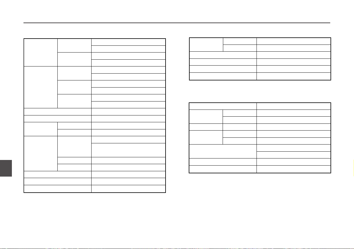
9. Specifications
●General ●Transmitter
●Receiver
144.000 - 147.995MHz (T Version)
144.000 - 145.995MHz (E Version)
420.000 - 449.995MHz (T Version)
430.000 - 439.995MHz (E Version)
88.100 - 107.995MHz (T Version)
87.500 - 107.995MHz (E Version)
108.000 - 173.995MHz (T Version)
144.000 - 145.995MHz (E Version)
380.000 - 511.995MHz (T Version)
430.000 - 439.995MHz (E Version)
F3E
50ohm (SMA)
3.7 - 6.0 VDC
3.7 VDC
DC6.0V: VHF Approx. 0.28A,UHF Approx. 0.32A
3.7V (EBP-58N): VHF Approx. 0.25A,
UHF Approx. 0.30A
Approx. 70mA
Approx. 19mA
-7 - +3 ppm (-10 - 60˚C)
58(W) x 96(H) x 14.5(D) mm
Approx. 102g (EBP-58N inclusive)
VHF
UHF
FM Radio
VHF
UHF
External Terminal
Battery Terminal
Transmit
Receive
Battery Save
TX
Frequency
Range
RX
Frequency
Range
Modulation
Antenna Impedance
Rated Voltage
Current
Frequency Stability
Dimensions (Projection exclusive)
Weight
Approx. 0.5W
Approx. 0.3W
Variable Reactance
+/- 5kHz
-60dB or less
Approx. 2.2kohm
Power Output
Modulation
Maximum Deviation
Spurious Emission
Microphone Impedance
DC6.0V
EBP-58N equipped
Double-conversion super heterodyne
IF 50.85MHz
IF 450kHz(AM/FM), 10.7MHz(WFM)
-15.0dBu or less
12kHz or over (AM/FM), 200kHz or over (WFM)
35kHz or over (AM/FM), 300kHz or over (WFM)
100mW or over (MAX)
90mW or over (10% Distortion factor 8ohm)
60dB or over
Approx. -16dBu or less
System
Intermediate
Frequency
Sensitivity
Selectivity
Audio Output
Spurious Response
Squelch Sensitivity
1st
2nd
(12dB SINAD)
-6dB
-60dB
Page 34

36
9
Specifications
VHF/UHF FM HANDHELD TRANSCEIVER 144.000 - 145.995MHz / 430.000 - 439.995MHz
This device is authorized for use in all EFTA member states (CH, ICE, LI, NOR).
An operator's license is required for this device.
AUS
F
I
E
B
D
LUX
S
DK
GR
NL
UK
FIN
IRE
P
CE0336!
Page 35

Page 36

Page 37

PS0463
Head Office: Shin-Dai Building 9th Floor
2-6-1 Dojimahama, Kita-ku, Osaka 530-0004, Japan
Phone: +81-6-4797-2136 Fax: +81-6-4797-2157
E-mail: export@alinco.co.jp
ALINCO, INC.
 Loading...