

Page 1
ALINCO, INC.
Yodoyabashi Dai-bldg 13F
4-4-9 Koraibashi, Chuo-ku, Osaka 541-0043 Japan
Phone: +81-6-7636-2362 Fax: +81-6-6208-3802
http://www.alinco.com
E-mail:export@alinco.co.jp
UHF FM Transceiver / 400-470MHz
All EU and EFTA member states. Operator
license is required.
Copyright Alinco, lnc. PS0786/FNEG-NI
Printed in China
A2.130808
Page 2
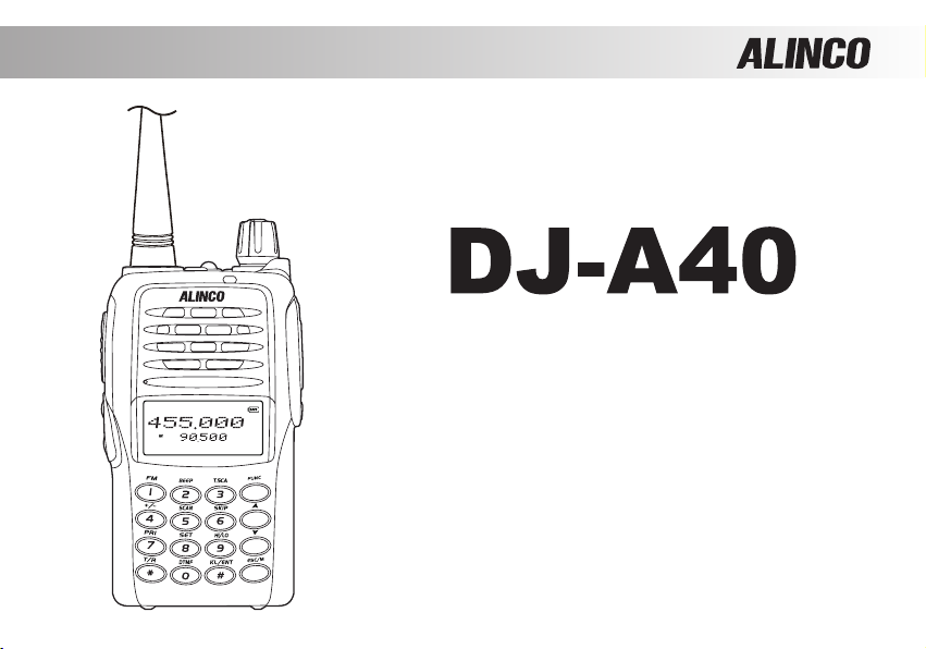
DJ-A40
UHF FM Transceiver
Instruction Manual
A
B
C
D
Thank you for purchasing your new Alinco transceiver. Please read this manual
care fully befo re using the prod uct to ensur e ful l performa nce, and keep thi s
manual for future reference as it contains information on after-sales service.
In case addendum or errata sheets are included with this product, please read
those materials and keep them together with this instruction manual for future
reference.
Page 3

Introduction
Thank you very much for purchasing this excellent Alinco transceiver. Our products are ranked among the
nest in the world. This radio has been manufactured with state of the art technology and it has been tested
carefully at our factory. It is designed to operate to your satisfaction for many years under normal use.
Please read this manual completely from the rst page to the last, to learn all the functions the
product offers. It is important to note that some of the operations may be explained in relation
to information in previous chapters. By reading just one part of the manual, you may risk not
understanding the complete explanation of the function.
Before transmitting
There are many radio stations operating in to the frequency ranges this product covers. Be careful not to
cause interference when transmitting around such radio stations.
■
Lightning
Any person is not safe outdoor during thunderstorm and lightning. This condition is getting worse if
somebody keeps a hand-held radio; chances of being hit by lightning are doubled since lightning may
hit a radio antenna as well. At this time, there is no hand-held radio having any kind of protection against
lightning current (which is higher than10 kA.). Note also that no car provides adequate protection of its
passengers or drivers against lightning as well. Therefore, Alinco will not take responsibility for any danger
associated with using its hand-held radios outdoor or inside the car during lightning.
■
About IP54 rating / Dust and splash resistant
About IP54 rating
Page 4

5: Dust protected /Ingress of dust is not entirely prevented, but it must not enter in sufcient quantity to
interfere with the satisfactory operation of the equipment; complete protection against contact.
4: Splashing water / Water splashing against the enclosure from any direction shall have no harmful effect.
Test duration: 5 minutes / Water volume: 10 litters per minute /Pressure: 80~100 kN/m²
The IP54 designation provides for limited dust and splash proong of the radio per specied above. This
compatibility is factory guaranteed for a period of one year provided all the jack covers are securely in
place, any accessories connected must be specied genuine Alinco accessories and the radio has not
been disassembled by the customer. The factory has tested and made the equipment compatible to IP54
certication during engineering. However, please understand that this equipment is NOT certied IP54
compliant but is designed to remain operational when used in hard conditions and is in no way stating
that you should attempt to wash the radio for cleaning. Warranty will not cover radios that are water/dust
damage due to negligence or misuse of the product.
The warranty period of dust and splash resistance is the same as the period of the product warranty.
■
Covering ranges
You may expect a range of approx.3km/2 miles or more at high-power when located on a at, noise-free
place like on a beach.However,it may vary drastically depending on how to wear and carry the radios,
surrounding locations/conditions and static noise levels (below or near power transmission lines), etc. In
urban areas with many buildings or inside a building, such covering range will become drastically short
even to several tens of meters.
Page 5

Features
■ Output power selectable 5W
■ 128 PC-programmable channels
■ Li-Ion battery pack and stand-charger as standard accessories
■ Alphanumeric name tags
■ FM broadcasting 76-108MHz receiver built-in
■ Selectable Battery-save parameters
■ Busy Channel Lockout
■ Voice Compander (Reduce Noise & enhance audio clarity)
■ Inversion Scramble(Analog encryption)
■ Sub-tone (CTCSS/DCS) Encode/ Decode and DTMF/ANI
■ VOX built-in
■ Voice prompt in English, Emergency Kill/Stun/Waken, Alarm signal, Various scan
modes, Key lock and more at NO extra costs.
Conformity Symbols
Tested to comply MIL-STD-810G
-Shock: Method 514.6/I,IV -Vibration: Method 516.6/I
Page 6

SAFETY TRAINING INFORMATION
Warning: Please Read Carefully
A transceiver generates RF (Radio Frequency) electromagnetic energy while transmitting. This Alinco
transceiver is designed for and classied as “Occupational Use Only", meaning it must be used minimum
necessary only during the course of employment by employees aware of the hazards, and the ways
to minimize such hazards. This transceiver is NOT intended for use by the “General Population” in an
uncontrolled environment. This transceiver has been required “SAR-Standard” tested and complies with
the FCC RF exposure limits for “Occupational Use Only”.
To ensure that your expose to RF electromagnetic energy is within the allowable limits for occupational
use, always adhere to the following guidelines:
DO NOT operate the transceiver without a proper antenna attached, as it may damage the transceiver
•
and may also cause you to exceed FCC RF exposure limits. A proper antenna is the genuine antenna
supplied with this transceiver by Alinco or ones specically authorized by the antenna manufacturer for
use with this transceiver.
DO NOT tran smit for m ore than 50% durin g the time of em ployment (50% du ty cycle or less).
•
Transmitting excess ive amount of time can cause RF exposure compliance requirements to be
exceeded. Please carefully read this instruction manual to learn how to transmit and stop transmitting
before starting to use it.
ALWAYS keep the antenna at least 3 cm (1 inch) away from your body when transmitting and only use
•
the original belt clips when attaching the transceiver to your body (Unauthorized attachment devices may
help radiating more electromagnetic energy). To obtain the best sound quality during communications,
hold the antenna at least 6 cm (2 inches) from your mouth, and slightly off to one side.
Page 7

Use only the genuine Alinco accessories listed in this instruction manual for RF safety. Third party
•
accessories are not guaranteed for RF safety by Alinco.
The above provides the information needed to make users of this transceiver aware of RF exposure, and
what to do to assure that this transceiver operates with the FCC RF exposure limits.
Electromagnetic Interference/Compatibility
•
During transmissions, a transceiver generates RF energy that can possibly cause interference with other
devices and/or systems.
To avoid such interference, turn off the transceiver in areas where signs are posted to do so. NEVER
operate transceivers in areas that are sensitive to electromagnetic radiation such as hospitals, blasting
sites, aboard aircraft and similar advanced vehicles etc. Do not expose magnetic cards such as credit
cards in a very close vicinity to a transceiver; it may erase the magnetic data. A person using medical
devices such as a pacemaker MUST NOT use this transceiver, as interference may cause malfunction to
such medical devices.
Occupational/Controlled Use
•
This product is used in situations that users are exposed to RF as consequence of their employment
provided those users are fully aware of the potential RF hazards and can exercise control over their
exposure.
This transceiver is NOT ATEX approved and NOT intended for the use in hazardous explosive
•
atmospheres.
California residents only: Please note per Proposition 65 that Li-Ion battery pack in this product
•
may contain chemicals known to the State of California to cause cancer and birth defects or other
reproductive harm.
Page 8

OR CUSTOMERS IN CANADA :
F
Le présent appareil est conforme aux CNR d'Industrie Canada applicables aux appareils radio
exempts de licence.
L'EXPLOITATION EST AUTORISéE AUX DEUX CONDITIONS SUIVANTES :
(1) l'appareil ne doit pas produire de brouillage, et
(2) l'utilisateur de l'appareil doit accepter tout brouillage radioélectrique subi, même si le brouillage est
susceptible d'en compromettre le fonctionnement.
Page 9

Alert
Environment and condition of use
Use of this product may be prohibited or illegal outside of your country. Be informed in advance when you
travel.
It is recommended that you check local trafc regulations regarding the use of a radio equipment while
driving. Some countries prohibit or apply restrictions for the operation of radios and mobile- phones while
driving.
Do not use this product in close proximity to other electronic devices, especially medical ones. It may
cause interference to those devices.
Keep the radio out of the reach of children.
In case a liquid leaks from the product, do not touch it. It may damage your skin. Rinse with plenty of cold
water if the liquid contacted your skin.
Never operate this product in facilities where radio products are prohibited for use such as aboard aircraft,
in airports, in ports, within or near the operating area of business wireless stations or their relay stations.
The manufacturer declines any responsibilities against loss of life and/or a property due to a failure of this
product when used to perform important tasks like life-guarding, surveillance, and rescue.
Do not use multiple radios in very close proximity. It may cause interference and/or damage to the
product(s).
Risk of explosion if battery is replaced with an incorrect type.
Page 10

The manufacturer declines any responsibilities against loss of life and property due to a failure of this product
when used with or as a part of a device made by third parties.
Use of third party accessory may result in damage to this product. It will void our warranty for repair.
Handling this product
Be sure to reduce the audio output level to minimum before using an earphone or a headset. Excessive
audio may damage hearing.
Do not open the unit without permission or instruction from the manufacturer. Unauthorized modication or
repair may result in electric shock, re and/or malfunction and voids warranty.
Do not operate this product in a wet place such as in a shower room. It may result in electric shock, re and/
or malfunction, This product is splash-proof but not a complete water-proof.
Do not place the product in a container carrying conductive materials, such as water or metal in close
proximity. A short-circuit to the product may result in electric shock, re and/or malfunction.
About chargers
Do not use adapters other than having the specified voltage. It may result in electric shock, fire and/or
malfunction,Never turn on the radio while charging.
Do not plug multiple devices using an adapter into a single wall outlet. It may result in overheating and/or re.
Do not handle adapter with a wet hand. It may result in electric shock.
Page 11

Securely plug the adapter into the wall outlet. Insecure installation may result in short-circuit, electronic shock
and/or re.
Do not use the adapter if the plug or socket contacts are dirty. Overheating and/or short-circuiting may result
in re, electric shock and/or damage to the product.
In case of emergency
In case of the following situation(s), please turn off the product, switch off the source of power,
then remove or unplug the power-cord. Please contact your local dealer of this product for service
and assistance. Do not use the product until the trouble is resolved. Do not try to troubleshoot the
problem by yourself.
When a strange sound, smoke and/or strange odor comes out of the product. ●
When the product is dropped or the case is broken or cracked. ●
When a liquid penetrated inside. ●
When a power cord (including DC cables, AC cables and adapters) is damaged ●
For your safety, turn off then remove all related AC lines to the product and its accessories from the wall outlet
if a thunderstorm is likely.
Maintenance
Do not open the unit and its accessories. Please consult with your local dealer of this product for service and
assistance
Page 12

Alert
Environment and condition of use
Do not use the product in proximity to a TV or a radio. It may cause interference or receive interference.
Do not install in a humid, dusty or insufciently ventilated place. It may result in electric shock, re and/or
malfunction.
Do not install in an unstable or vibrating position. It may result in electric shock, re and/or malfunction when/
if the product falls to the ground.
Do not install the product in proximity to a source of heat and humidity such as a heater or a stove. Avoid
placing the unit in direct sunlight.
Be cautious of a dew formation. Please completely dry the product before use when it happens.
About transceiver
Be cautious of the whip antenna when carried in your shirt-pocket etc. It may make contact with your eye and
cause injury.
Do not connect devices other than specified ones to the jacks and ports on the product. It may result in
damage to the devices.
Turn off and remove the power source (AC cable, DC cable, battery, cigar cable, charger adapter etc.) from
the product when the product is not in use for extended period of time or in case of maintenance.
Never pull the cord alone when you unplug AC cable form the wall outlet.
Page 13

Use a clean, dry cloth to wipe off dirt and condensation from the surface of the product. Never use thinner or
benzene for cleaning.
Check with your local waste ofcials for details on recycling or proper disposal of the electronics product,
battery-packs and accessories in your area.
PC PROGRAMMING
NOTE: The utility software may be available to distributors/dealers only. USB programming cable is required. The
manufacturer will not release the software to unauthorized party so please contact your dealer for details.
Page 14

TABLE OF CONTENTS
STANDARD ACCESSORIES .........................................................................................................................................01
Standard Accessories ................................................................................................................................................01
OPERATION MODE (VFO mode and Channel mode) ................................................................................................02
KEY OPERATIONS / QUICK CHART ...........................................................................................................................04
BATTERY INFORMATION .............................................................................................................................................11
Charging Operation ....................................................................................................................................................11
Battery Charger Type .................................................................................................................................................11
Notice for Charging Battery ........................................................................................................................................11
How to Charge the battery pack .................................................................................................................................13
INSTALLATION & CONNECTION .................................................................................................................................15
How to Store the Battery ............................................................................................................................................15
Installing / Removing the Li-ion Battery ......................................................................................................................15
Installing / Removing the Antenna ..............................................................................................................................16
Installing / Removing the Belt Clip .............................................................................................................................16
Accessories ................................................................................................................................................................17
Installing the Hand Strap ............................................................................................................................................17
GETTING ACQUAINTED ...............................................................................................................................................18
LCD Display ...............................................................................................................................................................18
Front Panel .................................................................................................................................................................19
Side Panel ..................................................................................................................................................................20
BASIC OPERATIONS ....................................................................................................................................................21
Power On and off .......................................................................................................................................................21
Adjusting Audio output level .......................................................................................................................................21
Emergency Alarm Function ........................................................................................................................................22
Change between Main Channel and FM Radio .........................................................................................................22
FM radio station scanning ..........................................................................................................................................22
Frequency Input by Keypad .......................................................................................................................................23
Professional
FM Transceiver
I
Page 15

TABLE OF CONTENTS
Channel Input by Keypad ...........................................................................................................................................23
Adjusting Channel / Frequency By "
Monitor / Squelch Off .................................................................................................................................................24
Receiving ...................................................................................................................................................................24
Transmitting................................................................................................................................................................25
Side Key【PF1】Function Instruction ........................................................................................................................25
Side Key【PF2】Function Instruction ........................................................................................................................26
Switch between VFO and Frequency+Channel Mode ...............................................................................................26
ADVANCED OPERATIONS ...........................................................................................................................................27
Editing Channels ........................................................................................................................................................27
Deleting Channels ......................................................................................................................................................27
Turn On/ Off FM Radio receiver .................................................................................................................................27
Enable /Disable Beeping ............................................................................................................................................28
CTCSS / DCS Scan(Works only when CTCSS/DCS are preprogrammed) ...............................................................28
Offset Frequency Direction Setup ..............................................................................................................................28
Frequency/Channel Scan ...........................................................................................................................................29
Channel Scan Skip .....................................................................................................................................................30
Priority Scan(Preprogramming of PRI channel is required) .......................................................................................30
DTMF Code Enquiry and Setup .................................................................................................................................31
Manually Transmitting DTMF Tones ...........................................................................................................................31
Remotely Kill / Revive ................................................................................................................................................33
Remotely Stun / Revive ..............................................................................................................................................33
Frequency Reverse / Talk Around ON/OFF ...............................................................................................................34
Keypad Lock ..............................................................................................................................................................35
Operating Parameter Setting......................................................................................................................................35
Tone Squelch / DCS squelch (Sub tone CTCSS / DCS ) Decode Tone Setup ..........................................................36
Tone Squelch / DCS squelch (Sub tone CTCSS / DCS ) Encode Tone Setup ..........................................................36
Professional
II
FM Transceiver
【B】
" Key & "
【C】
" Key ..............................................................................23
Page 16

TABLE OF CONTENTS
Tone Squelch / DCS squelch (Sub tone CTCSS / DCS) Encode/Decode tones synchronized setup .......................37
Offset Frequency ........................................................................................................................................................38
Frequency Reverse or Talk Around ............................................................................................................................38
Inversion scrambling (Encryption) ..............................................................................................................................39
Voice Compander (Reduce noise & enhance audio clarity) .......................................................................................39
Busy Channel Lockout ...............................................................................................................................................40
Turn On/Off Optional Signaling function .....................................................................................................................41
Signaling Relations ....................................................................................................................................................42
PTT ID ........................................................................................................................................................................43
TX OFF (Transmission Prohibited) ...........................................................................................................................43
Whisper ......................................................................................................................................................................44
SET MODE OPERATIONS ............................................................................................................................................45
Set Mode Setting ........................................................................................................................................................45
Voice Prompt ..............................................................................................................................................................45
Time-Out-Timer(TOT).................................................................................................................................................46
Voice Operated Transmission (VOX)(An optional earphone-microphone is necessary)............................................46
VOX Delay ................................................................................................................................................................47
VOX Beep .................................................................................................................................................................47
Frequency Step Size Setup .......................................................................................................................................48
Squelch Level .............................................................................................................................................................48
Battery Save ..............................................................................................................................................................49
LCD Backlight operation ............................................................................................................................................49
LCD Backlight Color Setup ........................................................................................................................................50
Scan Resume Time ....................................................................................................................................................50
Frequency/Channel Display Mode .............................................................................................................................51
Tone Burst Tone ........................................................................................................................................................51
DTMF Transmitting Time ............................................................................................................................................52
Professional
FM Transceiver
III
Page 17

TABLE OF CONTENTS
Beep Volume level .....................................................................................................................................................52
Priority Channel Setup ...............................................................................................................................................53
Current Battery Voltage Display .................................................................................................................................53
Resume Factory Default (RESET) .............................................................................................................................54
DEFAULT SETTINGS ...................................................................................................................................................55
OPTIONAL ACCESSORIES ..........................................................................................................................................56
RECOMMENDED INSTALLATION OF EARPHONE MICROPHONE...........................................................................57
TECHNICAL SPECIFICATIONS ....................................................................................................................................58
TROUBLE SHOOTING GUIDE ......................................................................................................................................60
ATTACHED CHART .......................................................................................................................................................62
CTCSS Frequency Chart ...........................................................................................................................................62
DCS Chart ..................................................................................................................................................................63
Professional
IV
FM Transceiver
Page 18
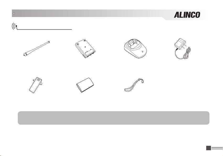
STANDARD ACCESSORIES
Standard Accessories
Antenna Battery
Belt Clip Instruction
Charger AC Adaptor
Hand Strap
Manual
NOTE: Accessories may differ depending on the version you have purchased. Please contact your local
dealer for details of standard accessories and the warranty-policy before purchase.
Professional
FM Transceiver
01
Page 19

OPERATION MODE (VFO mode and Channel mode)
You may set the radio as VFO mode and Channel mode. There are also different setting parameters to
properly set functions as per your operating comfort.
1. By programming software:
In PC programming utility software, "General Setting" menu, choose "Display Mode" to select VFO
mode or Channel mode.
2. By manual setup:
Please refer to "Display Mode" in Page 51.
VFO Mode: In this mode, press
A.Memory mode/Freq.+channel display: At this mode, when set display as
FREQ
"
", it enters into Frequency + Channel mode. Once the radio is turned
off or switched to another channel, the temporary setting will be erased and
back to initial settings. (As pic 1)
B.Memory mode/Name tag+channel number display: When set display as
NAME
"
", it will display corresponding channel name when the current channel
is edited with name in advance. Otherwise, it will display frequency and
channel number. Its operations are the same as frequency + channel mode.
(As pic 2)
C.VFO Mode(Frequency mode): This mode shows only frequency on the
display. Set mode operation and Channel setting are stored as the latest
value. Once the radio is turned off or changed to new frequency using VFO,
the value remains until next change. (As pic 3)
Professional
02
FM Transceiver
【D】
key to switch between Channel mode and VFO.
(Pic 1)
(Pic 2)
Page 20

OPERATION MODE (VFO mode and Channel mode)
3.Commercial radio Mode:
When set display mode as "CH", it enters into Commercial radio mode. At this
mode, except scanning, talk around/frequency reverse, DTMF encode or editing,
BEEP on/off and keypad lock, all other functions should be set by PC software
in advance to the operation (As pic 4). If name tag is programmed, the LCD will
display current channel and name tag. (As pic 5)
NOTE: In Commercial radio mode, you can't switch the mode to VFO or
channel manually, but you must use PC utility software.
4. In each operating mode, access to the set mode is possible.
(Pic 4)
(Pic 5)
Professional
FM Transceiver
03
Page 21
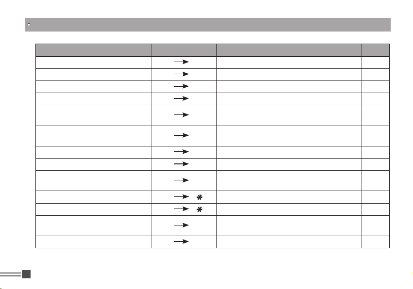
KEY OPERATIONS / QUICK CHART
Function Key Operation Parameter Instruction Page
FM Radio On/Off
Beep Setup
CTCSS/DCS Scan
CTCSS/DCS Scan
Offset Frequency Direction Setup
Offset Frequency Direction Setup
Scan
Channel Scan Skip
Priority Scan
Frequency Reverse / Talk Around
Frequency Reverse / Talk Around
DTMF Code Enquiry
Keypad Lock
Professional
04
FM Transceiver
【A】 【1】
【A】 【2】
【A】 【3】
【A】 【3】
【A】 【4】
【A】 【4】
【A】 【5】
【A】 【6】
【A】 【7】
【A】 【 】
【A】 【 】
【A】 【0】
【A】 【#】
Activate FM broadcasting receiver
Beep sound ON/OFF
CTCSS Scan
DCS Scan
(+):Transmitting frequency higher than
receiving frequency
(-):Transmitting frequency lower than
receiving frequency
Channel or Frequency Scan
S: Scan without current channel
PRI: Check priority channel one time when
scan each 10 channels
R: Frequency Reverse
T: Talk Around
Displaying “-” when no data
Displaying data when being with data
All keys locked, except PTT/PF1/ PF2
27
28
28
28
28
29
29
30
30
34
34
31
35
Page 22
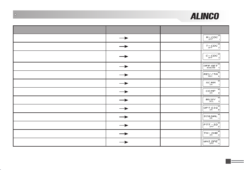
KEY OPERATIONS / QUICK CHART
Function Key Operation Function Option Display
【
】 【8】 【B】/【C】
Sub tone (CTCSS / DCS) Decode Setup
Sub tone (CTCSS / DCS) Encode Setup
Sub tone (CTCSS / DCS) Encode/Decode
Synchronous Setup
Offset Frequency
Frequency Reverse/Talk Around
Scramble Setup( Encryption)
Voice Compander Function
Busy Channel Lockout
Add Optional Signaling
Signaling Relations
PTT ID Setup
TX Off Function
Whisper
A
【
】 【8】 【B】/【C】
A
【
】 【8】 【B】/【C】
A
【
】 【8】 【B】/【C】
A
【
】 【8】 【B】/【C】
A
【
】 【8】 【B】/【C】
A
【
】 【8】 【B】/【C】
A
【
】 【8】 【B】/【C】
A
【
】 【8】 【B】/【C】
A
【
】 【8】 【B】/【C】
A
【
】 【8】 【B】/【C】
A
【
】 【8】 【B】/【C】
A
【
】 【8】 【B】/【C】
A
Professional
FM Transceiver
05
Page 23

KEY OPERATIONS / QUICK CHART
Key Operation Parameter Instruction Enter and exit Page
Sub-tone setting:
Op er at io ns are common to Deco de (R-CDC) ,
Encode (T-CDC) and Synchronous (C-CDC). Press
【
】
A
Key to move cursor to the menu, Press
Key to choose CTCSS/DCS/OFF, Press
Key to choose the value ,
DCS inverted and positive code.
Offset frequency shift value:
【
】
A
Press
【B】/【C】
Frequency reverse / Talk-around:
Press
【B】/【C】
Inversion scrambling:
Press
Press
Voice Compander:
Press
【B】/【C】
N o t e : Do no t activate th is f u n c t i o n wh il e
communicating with Non-Compander radios.
06
Key to move cursor to the menu, Press
Key to choose the value.
【
】
A
Key to move cursor to the menu, Press
Key to choose the value.
【
】
A
Key to move cursor to the value of menu,
【B】/【C】
【
】
A
Key to move cursor to the menu, Press
Key to choose the value.
Professional
FM Transceiver
【#】
Key to choose the value.
【B】/【C】
Key to choose correct
CTCSS (50 Groups in total): 67Hz-254.1Hz
【1】
DCS (232Groups in total): 017N-765I
Available parameters are 0-70Mhz.
REV : Frequency Reverse TA : Talk Around
OFF: Disable scramble ON: Enable scramble
ON: Enable compander
OFF: Disable compander
【D】/【#】
【D】/【#】
【D】/【#】
【D】/【#】
【D】/【#】
36
38
39
39
40
Page 24

KEY OPERATIONS / QUICK CHART
Key Operation Parameter Instruction Enter and exit Page
Busy-Channel-Lockout (BCL):
Press【A】Key to move cursor to the menu, Press
【B】/【C】Key to choose the value.
Adding Optional Signaling tones:
Press【A】Key to move cursor to the menu, Press
【B】/【C】Key to choose the value.
DCS (232Groups in total):017N-765I
Signaling relations:
Press【A】Key to move cursor to the menu, Press
【B】/【C】Key to choose the value.
PTT ID Setup (DTMF encoding):
Press【A】Key to move cursor to the menu, Press
【B】/【C】Key to choose the value.
TX OFF (PTT lock):
Press【A】Key to move cursor to the menu, Press
【B】/【C】Key to choose the value.
Wh is pe r (En hanc e voice lev el while ta lk in g in
undertones):
Press【A】Key to move cursor to the menu, Press
【B】/【C】Key to choose the value.
OFF: Disable
BCL: Prohibit transmitting when receiving a carrier
and squelch is open.
BTL: Prohibit transmitting when receiving a carrier
with unmatched signaling.
CTCSS (50 Groups in total):67Hz-254.1Hz
AND: The other parties' traffics can be heard as
long as the matched CTCSS / DCS signal AND
optional signal are received.
OR: The other parties' traffics can be heard as long
as the matched CTCSS / DCS signal OR optional
signal is received.
OFF: Disable PTT ID
BOT: Press PTT key to transmit DTMF tones
EOT: Release PTT key to transmit DTMF tones
BOTH: Pr ess an d Releas e PTT key ca n both
transmit DTMF tones
ON: Enable TX Off function
OFF: Disable TX Off function
ON: Enable whisper function
OFF: Disable whisper function
【D】/【#】
【D】/【#】
【D】/【#】
【D】/【#】
【D】/【#】
【D】/【#】
40
41
42
43
43
44
Professional
FM Transceiver
07
Page 25
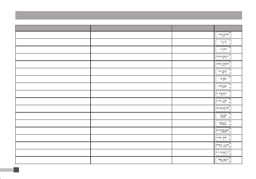
KEY OPERATIONS / QUICK CHART
Function Menu Entry Function Option Display
Voice Prompting Selection Press PF2 and hold this key for 3 seconds
Time-Out Timer (TOT) Press PF2 and hold this key for 3 seconds
Voice Operated Transmission (VOX) Setup Press PF2 and hold this key for 3 seconds
Voice Operated Transmission (VOX) Delay Press PF2 and hold this key for 3 seconds
Voice Operated Transmission (VOX) Beep Press PF2 and hold this key for 3 seconds
Frequency Step Setup Press PF2 and hold this key for 3 seconds
Squelch level Setup Press PF2 and hold this key for 3 seconds
Battery Save Setup Press PF2 and hold this key for 3 seconds
LCD Backlight Setup Press PF2 and hold this key for 3 seconds
LCD Backlight Color Press PF2 and hold this key for 3 seconds
Scan Dwell Time Setup Press PF2 and hold this key for 3 seconds
Display Mode Setup Press PF2 and hold this key for 3 seconds
Tone Pulse Frequency Setup Press PF2 and hold this key for 3 seconds
DTMF Transmitting Time Setup Press PF2 and hold this key for 3 seconds
Beep Volume Control Press PF2 and hold this key for 3 seconds
Priority Channel Setup Press PF2 and hold this key for 3 seconds
Current Battery Voltage Enquiry Press PF2 and hold this key for 3 seconds
Resume Factory Default Press PF2 and hold this key for 3 seconds
Professional
08
FM Transceiver
【B】/【C】
【B】/【C】
【B】/【C】
【B】/【C】
【B】/【C】
【B】/【C】
【B】/【C】
【B】/【C】
【B】/【C】
【B】/【C】
【B】/【C】
【B】/【C】
【B】/【C】
【B】/【C】
【B】/【C】
【B】/【C】
【B】/【C】
【B】/【C】
Page 26

KEY OPERATIONS / QUICK CHART
Parameter Adjustment Parameter Instruction Confirm to back Page
Press
Press
Press
Press
Press
Press
Press
Press
Press
Press
Press
Press
Press
Press
Press
Press
Press
Press
【
】
A
Key to move cursor to the menu
【B】/【C】
【
【B】/【C】
【
【B】/【C】
【
【B】/【C】
【
【B】/【C】
【
【B】/【C】
【
【B】/【C】
【
【B】/【C】
【
【B】/【C】
key to choose the value
】
A
Key to move cursor to the menu
key to choose the value
】
A
Key to move cursor to the menu
key to choose the value
】
A
Key to move cursor to the menu
key to choose the value
】
A
Key to move cursor to the menu
key to choose the value
】
A
Key to move cursor to the menu
key to choose the value
】
A
Key to move cursor to the menu
key to choose the value
】
A
Key to move cursor to the menu
key to choose the value
】
A
Key to move cursor to the menu
key to choose the value
Voice prompt:
ENG: Activate English Voice-guide
OFF: OFF
Time-out-timer setting:
Selectable parameter: 15 seconds to 240 seconds
OFF: TOT Off
VOX activation and its operational audio level:
Audio level parameter: 1, 2, 3
OFF: VOX OFF
VOX delay time (Time delay from end of TX to switch to
RX)
10 parameters between 0.5 seconds to 5 seconds
ON: Enable VOX beep
OFF: Disable VOX beep
VFO frequency step:
Available Steps: 5KHz/ 6.25KHz/ 10KHz/ 12.5KHz
Squelch level setting:
Available level settings : 0 (opens squelch) to 9
Battery-save ratio:
4 different ratios (1:1 to 1:4) are available. 1:4 to obtain the
best battery save effort but your risk to miss initial part of
receiving signals becomes higher.
OFF: Disable Battery-save function
LCD backlight operation
OFF: Turned off always
ON: Turned on always (consumes battery much faster)
AUTO: Turns on with the key operation then turns off
automatically
【D】/【#】
【D】/【#】
【D】/【#】
【D】/【#】
【D】/【#】
【D】/【#】
【D】/【#】
【D】/【#】
【D】/【#】
45
46
46
47
47
48
48
49
49
Professional
FM Transceiver
09
Page 27

KEY OPERATIONS / QUICK CHART
10
Press
Press
Press
Press
Press
Press
Press
Press
Press
Press
Press
Press
Press
Press
Press
Press
Press
Press
【
】
A
Key to move cursor to the menu
【B】/【C】
【
【B】/【C】
【
【B】/【C】
【
【B】/【C】
【
【B】/【C】
【
【B】/【C】
【
【B】/【C】
【
【B】/【C】
【
【B】/【C】
Professional
FM Transceiver
key to choose the value
】
A
Key to move cursor to the menu
key to choose the value
】
A
Key to move cursor to the menu
key to choose the value
】
A
Key to move cursor to the menu
key to choose the value
】
A
Key to move cursor to the menu
key to choose the value
】
A
Key to move cursor to the menu
key to choose the value
】
A
Key to move cursor to the menu
key to choose the value
】
A
Key to move cursor to the menu
key to choose the value
】
A
Key to move cursor to the menu
key to choose the value
LCD backlight color selection:
BLUE: Blue backlight
ORG: Orange backlight
PUR: Purple backlight
Scan resume time setting:
3 parameters: 5 seconds / 10 seconds / 15 seconds
Display mode: (May be preprogrammed by dealer and
locked)
FREQ: Frequency and Channel display
CH: Channel display
NAME: Channel number with name-tag display if
programmed
Tone-Burst tones:
4 tones available: 1750Hz / 2100Hz / 1000Hz / 1450Hz
DTMF tone transmitting time:
10 parameters including 50Microseconds, 100Ms, 150Ms,
200Ms, 250Ms,300Ms, 350Ms, 400Ms, 450Ms, and 500Ms
Beep volume level:
5 levels from 1 to 5
Priority scan channel setup:
Select one from available programmed channels
OFF: Disable Priority Channel
Battery-voltage display (approx)
Display current battery voltage
Perform RESET
FACT? : Resume Factory Default, erasing the memory
channels
INIT? : Resume General Setting, keeping memory channel
programming
OFF: Cancels reset
【D】/【#】
【D】/【#】
【D】/【#】
【D】/【#】
【D】/【#】
【D】/【#】
【D】/【#】
【D】/【#】
【D】/【#】
50
50
51
51
52
52
53
53
54
Page 28

BATTERY INFORMATION
Charging Operation
The battery is not charged at the factory, so please charge it before use. Charge the battery for the rst
time after purchase or extended storage (more than 2 months) may not bring the battery to its normal
operating capacity. After repeating fully charge/ discharge cycle, the operating capacity will reach the
best performance. The battery life is over when its operating time decreases even though it is fully and
correctly charged.and it must be replace to new one.
Battery Charger Type
Please use Alinco's designated charger, other models may cause explosion and injury. After installing
the battery, when the radio displays low battery, please charge the battery.
Notice for Charging Battery
▲Do not shortcircuit the charger. Never attempt to remove the casing from the battery, otherwise the
warranty is void and you risk serious damage to yourself and properties.
▲The ambient temperature should be between 5℃ and 40℃ in charging. Charging outside this range
may not fully charge the battery.
▲Always switch off the transceiver equipped with a battery before charging. Otherwise, it will interfere
with correct charging.
▲To avoid interfering the charging procedure, please do not cut off the power or take out the battery
during charging.
▲Do not recharge the battery if it is already fully charged. This may shorten the life of the battery or
damage the battery.
▲Do not charge the battery or transceiver when wet. Dry it before charging to avoid danger.
Professional
FM Transceiver
11
Page 29

BATTERY INFORMATION
Caution
• Risk of explosion, generation of heat or leak of chemicals inside if the battery is replaced by an
incorrect type or reverse polarity. Use always the recommended types of batteries in this manual only.
• The battery pack isn't fully charged when shipped. It must be charged before use.
• Charging should be conducted in a temperature range of +5ºC to +40ºC (+41ºF to +104ºF).
• Don't modify, dismantle, incinerate or immerse the battery pack in the water as this can be dangerous.
• Never short-circuit the battery pack terminals, as this can cause damage to the equipment or lead to
heating of the battery which may cause burns.
• Unnecessary prolonged charging (overcharging) can deteriorate battery performance.
• The battery pack should be stored in a dry place where temperature is in -10ºC to +45ºC (-14ºF to
+113ºF) range. Temperatures outside this range can cause the battery liquid to leak. Exposure to
prolonged high humidity can cause corrosion of metal components.
• Battery-packs are a consuming part. When its operating time becomes considerably short after a
normal charge, please consider that the pack is exhausted and replace it with a new one.
• The battery pack is recyclable. Check with your local waste ofcials for details on recycling options or
proper disposal in your area.
• Use specified genuine chargers only to charge battery packs. Use of other chargers may cause
damage to products, you and your property.
• Never carry battery packs together with conductive articles such as metals in a same bag to prevent
from short-circuiting. Put the packs only in nylon bags to carry them safely.
Professional
12
FM Transceiver
Page 30

BATTERY INFORMATION
How to Charge the battery pack
1.Plug the AC adaptor into the AC outlet, then plug into the
DC jack ,the indicator lights orange for 1 second and goes
out---waits to charge.
2.Slide the battery or transceiver with batt er y into th e
charger; make sure the battery terminals are in contact
with the charging terminals . LED turns into twinkling RED
---pre-charging begins.
3.Pre-charging for about 5 minutes, LED stops blinking then
charging up to.
4.It takes 4 hours to fully charge the battery, and LED turns to green when the charge is complete.
Warning: Never charge while the radio is turned on. When turned on, the charger can't detect the
charging voltage properly and LED fails to indicate charge status correctly.
5. LED Indicator:
STATUS
LED
self-examine
when power on
Orange
(for 1 second)
(No battery) Pre-charging
None
Red light twinkles
for 5 minutes
Charge
normally
Fully
Charged
Red Green
Trouble
Red twinkles
alternatively
Professional
FM Transceiver
13
Page 31

BATTERY INFORMATION
NOTE:
▲ Trouble means battery heating, short-circuit or charger malfunction. Remove the battery pack from
the charger immediately and contact to your local dealer for services.
▲ The max trickle pre-charging time is 30 minutes. In case the red indicator continues to blink longer,
please stop charging and consult with your local dealer for services.
▲ It is known that Li-Ion battery packs heat up over 400℃ by itself when kept in a temperature of over
80℃ for extended period of time. Although the packs are protected against overheating with a protective
circuit, never leave the battery packs in a car or similar locations in hot seasons.
▲ Li-ion packs may deteriorate by over 30% regardless of conditions after 3 years. This is a nature of Liion pack and not a defect of the product.
▲ The charger is to charge the battery pack only. It is not an AC adapter to operate the radio. Never
attempt to transmit the radio with using the charger as it will cause the damage to the charger and a
repair/replace may become necessary.
▲ The charge should be conducted in an ambient temperature with a minimum proper air-conditioning
in an extremely hot or cold seasons.
▲ Try charging the battery pack only when having trouble charging with the radio.In case the radio may
have troubles,the charge can't be conducted properly.If the battery pack can be charged alone, please take
the radio to your local dealer for services.
Professional
14
FM Transceiver
Page 32

INSTALLATION & CONNECTION
How to Store the Battery
1.The battery should be kept in the status of 50% discharge when storing.
2.Remove the battery pack from the radio and keep it in a cool, dry place.
3.Keep away from source of heat and direct sunlight.
NOTE: Incorrect storage will damage both the battery pack and the radio. Please always remove the
battery pack from the radio when not in use.
Installing / Removing the Li-ion Battery
1.Match the three grooves of the battery pack with the
corresponding guides on the back of the transceiver,
then push it.
2.Press the battery and transceiver firmly together until the
release latch on the top of the transceiver locks. After
hearing a“click”sounds, the battery has been locked.
3.To remove the battery, slide up the release latch and
remove the pack away from the transceiver.
Professional
FM Transceiver
15
Page 33

INSTALLATION & CONNECTION
Installing / Removing the Antenna
Installing the Antenna:
1. Hold the antenna by its base.
2. Align the grooves at the base of the antenna with the protrusions
on the antenna connector.
3. Slide the antenna down and turn it clockwise until it stops.
4. Confirm that the antenna is securely connected.Check and secure the
connection from time to time.
Removing the Antenna:
Turn the antenna counter-clockwise to disconnect the antenna.
NOTE: Do not use third-party antenna as it may radiate more RF
that exceeds SAR limit guidances.
Installing / Removing the Belt Clip
Installing the Belt Clip:
1. Put the belt clip on the back of the unit, and the screw clockwise until it stops.
2. Conrm that the belt clip is securely attached.
* Tighten up the screw occasionally.
Removing the Belt Clip:
Turn the screw counter-clockwise to remove the belt clip.
Caution: Use the screws of specified size only. Others may cause
damage to the product. (screws size PM Φ 2.5mm x 3mm)
Professional
16
FM Transceiver
K
C
O
L
N
U
Page 34

INSTALLATION & CONNECTION
Accessories
Open the jack cover and insert the accessory
plug into the jack,as shown.
When the accessory is not used, please be
sure to close the cover securely.
NOTE:
1.To keep the radio dust and splash resistant, the
cover must be closed properly with the original
supplied cover.
2.The radio is not dust and splash resistant while
using the optional accessory risking th at the
water may penetrate inside through the plug.
Installing the Hand Strap
Attach the hand strap as shown.
Professional
FM Transceiver
17
Page 35

GETTING ACQUAINTED
LCD Display
Following are the meaning of the icons and signs shown on the display.
Some icons may not appear while operating this product due to pre-programming status by your dealer.
Frequency Reverse
Offset direction
DCS
Talk Around
CTCSS
FUNC Icon
FM radio
TX Power
Priority Scan
VOX Function
Scan Skip
Narrow band
Scramble (Encryption)
Battery Capacity
Function Menu Serial
No. / Main Channel
No. serial No.
Busy Channel
NOTE:
Battery capacity indicator(full) No power,replace battery pack or charge battery
Battery power consuming Real time display receiving signal
strength/Power Indicator
Professional
18
FM Transceiver
Keypad Lock
Page 36

GETTING ACQUAINTED
Front Panel
Antenna
Emergency Alarm
Speaker
Microphone
LCD
Numeric keys
Jacklight
Power / Volume
Switch
LED Indicator, red light
when transmitting, green
light when receiving
A
B
C
D
A key/Function key
B key / Up key
C key / Down key
D key, Exit key
or channel/VFO
Exchange key
Professional
FM Transceiver
19
Page 37

GETTING ACQUAINTED
Side Panel
PF1 key (1 Primary
Function key)
PF2 key (2 Primary
Function key)
Professional
20
FM Transceiver
PTT key
st
nd
PTT
MIC/SP
Left Panel Right Panel
Accessory and PC
programming port
Belt Clip
Battery
Page 38

BASIC OPERATIONS
Power On and off
Turn【POWER】/【VOLUME】dial clockwise to power on.
Turn it counterclockwise to power off.
Adjusting Audio output level
Press and hold PF2 key to monitor white noise to refer to the current audio
level.
Turn【POWER】/【VOLUME】cl ock w ise to inc rea s e t he audi o l eve l,
counterclockwise to decrease.
CAUTION:
NEVER USE EARPHONE while adjusting audio level. The max audio output is 1W, and it’s loud
enough to hurt your eardrums.
You may feel a static shock when wearing an earphone in a dry atomosphere but it's not a defect of
product but a cause of nature.It is the same shock you feel typically when opening a door of a car in
certain conditions.
Professional
FM Transceiver
21
Page 39

BASIC OPERATIONS
Emergency Alarm Function
While Stand-by state, press this key for 3 seconds to enable the emergency
alarm function. When activated the function, the radio will sound an alarm beep
and start transmitting the alarm beep. The alarming lasts 1 minute, then the
radio will return to Stand-by, or you may press this key again to stop alarming.
Change between Main Channel and FM Radio
】
【
A
Press
receiver. When switching to FM radio, the radio will automatically start receiving both FM radio
frequency and Main Channel. An arrow directs the current operational channel.
NOTE: While receiving FM radio, only the following functions are supported: Channel editing, channel
deletion, keypad lock and beeping on/off. Other functions are available only for main channel.
key and then press
【1】
key to switch between Main Channel and FM broadcasting
FM radio station scanning
】
【
While listening to the FM broadcasting, press
received, LCD displays current frequency and stops scanning.
Repeat the key operation to exit the FM radio station receiving.
Professional
22
FM Transceiver
B
key or
【C】
key to start scanning. When a signal is
Page 40

BASIC OPERATIONS
Frequency Input by Keypad
In VFO mode or FM radio receiver, You may directly enter frequency through numeric keys.
【
】
1.Press
2.Enter the desired frequency in 6-digit by numeric keys.
Example: To enter 455.0125, press[4][5][5][0][1][2]then 5 appears and sets
automatically.To enter 455.100, press [4][5][5][1][0][0]. By pressing the last [0], a dot appears after the
MHz unit and the frequency is set.When an invalid numbers are entered, the display will return to the
current state and an error beep sounds.
NOTE: This product operates in accordance with legally assigned frequnecy only. In the FM receiver
mode, the frequency step size input by numeric keys is 50KHz.
D
to switch to VFO.
Channel Input by Keypad
In Frequency + Channel or Channel + Name Tag mode, you may select the channel by entering three
channel digits (001-128). If the entered channel has not been preprogrammed, a beep sounds to alert
you that input is wrong and then return to current channel.
Adjusting Channel / Frequency By "
】
In VFO mode, you may use
【B】
Press
channel step.
to increase,
【C】
【
【C】
B
key/
key to decrease the frequency. Every press moves frequency by a
key as up/down keys to change the operating frequency.
【B】
" Key & "
【C】
" Key
Professional
FM Transceiver
23
Page 41

BASIC OPERATIONS
NOTE: Available channel steps: 5K, 6.25K, 10K, 12.5KHz in total 4 for option. Please refer to stepping
frequency setup in the SET-MODE chapter.
】
In Channel mode, press
【
【C】
B
key/
enter the downward channel while press
key to choose the desired channel. Press
【C】
key to enter the upward channel..
【B】
key once to
Monitor / Squelch Off
In case the receiving signal is weak and the audio is intermittently cut off by the squelch, press and
hold【PF2】key. As long as this key is pressed, the squelch including TSQ/DCS unmutes making the
audio easier to hear. Press it again to close.
Receiving
Press[PF1] key to turn on the LED located on the upper panel. Repeat it to turn off. Use it only
necessary as it consumes battery considerably.
Select the operating mode and frequency or channel that you wish to operate.
When a signal is received on the frequency that you selected, and S-meter is displayed on the LCD,
then the received signal can be heard. The RX indicator also lights green at this time.
NOTE: Please be aware of the squelch level and selective-calling settings such as CTCSS and DCS as
you may risk not hearing the receiving signal.
Professional
24
FM Transceiver
Page 42

BASIC OPERATIONS
Transmitting
1. Select the frequency by using the dial or keypad.
2. Press the PTT key. The red TX indicator turns on while transmitting.
3. While holding down the PTT key, speak into the unit at normal voice from the distance of 5cm (2").
4. Release the PTT key to receive.
Before transmitting, it is recommended to monitor the channel you are going to use to ensure it is not
busy by pressing and holding【PF2】key.
Side Key【PF1】Function Instruction
【
PF1】Key is assigned to multiple functions:
Default setting: Press this key once to turn on/ off jacklight.
1. DTMF code TX: In stand-by conditions, press this key to transmit pre-stored DTMF tones.
2. Alarm:Press this key to start alarm function.(Optional:Preprogramming is necessary)
3. Alarm Off: In the alarm mode, press this key to stop the alarm.(Optional:Preprogramming is necessary)
4. Jacklight Switch: In stand-by, press this key to switch on or off the jacklight.
5. Tone-burst tone transmitting: While transmitting, press and hold this key to send the selected tone burst tone.
Professional
FM Transceiver
25
Page 43

BASIC OPERATIONS
Side Key【PF2】Function Instruction
Default setting: Monitor function
1. Monitor function: In stand-by state, press and hold this key to open the squelch and monitor the
channel. Release the key to Exit.
2. Turning on with this key pressed and hold it for 3 seconds to enter to the parameter.
Switch between VFO and Frequency+Channel Mode
】
【
D
Press
Channel+Name Tag mode.
NOTE: When the channel hasn’t been preprogrammed, this operation is unavailable.
Professional
26
FM Transceiver
key to switch between frequency mode (VFO) and Frequency + Channel mode or
Page 44

ADVANCED OPERATIONS
Editing Channels
1.In VFO mode, enter the frequency and set the operating parameters as you desire. After pressing
key, While
sounds and LCD displays the channel No. icon.
2.Press
"- - - - - -" if current channel name is not preprogrammed.
3.After pressing and holding
completes the operation.
icon is displayed on the top left corner, press and hold
【
】/【C】
B
key to select desired channel number. LCD will display
【
】
D
key for 2 seconds, a beep sounds and
Deleting Channels
In the Channel mode, select the channel to be deleted. After pressing
displayed on the top left corner, press and hold
another channel. The channel is deleted and completes the operation.
】
【
D
key for 2 seconds. A beep sounds and skips to
Turn On/ Off FM Radio receiver
】
【
A
In Stand-by conditions, after pressing
the top left corner, press
broadcasting frequency. Repeat the operations to turn off.
】
【
key. LCD displays 'FM' and starts receiving FM
1
key, While
icon is displayed on
【
】
D
key for 2 seconds. A beep
】
【
A
key, While
【
icon is
Professional
FM Transceiver
】
A
27
Page 45

ADVANCED OPERATIONS
Enable /Disable Beeping
Beep sounds to conrm or alert the operation status.
】
【
A
【
A
key, While
】
key, While
In Stand-by conditions, after pressing
the top left corner, press
sounds.
CTCSS / DCS Scan
In Stand-by conditions, after pressing
top left corner, press
【C】
key or
with the radio’s signaling setting, it will stay tuned for 15 seconds and resumes
scanning. Press any key except
NOTE: This function is not available in Commercial radio mode and no sub tone
is received in current channel. In current channel, if signaling sets as CTCSS, it
will scan CTCSS, if signaling sets as DCS, it will scan DCS.
key to change the scan direction. When the matched tone is detected
】
【
2
key to turn off the beep. Repeat it to enable beep
(Works only when CTCSS/DCS are preprogrammed)
】
【
3
key to activate CTCSS / DCS Scanning. Press
【A】,【 】,【#】
icon is displayed on
icon is displayed on the
keys to exit.
Offset Frequency Direction Setup
In VFO mode, frequency + channel mode or channel + name tag mode, after
Professional
28
FM Transceiver
【B】
Page 46

ADVANCED OPERATIONS
pressing
【
】
A
key, while
icon is displayed on the top left corner, press
】
【
4
key to choose positive offset direction (+), minus offset direction (-) or exit setting
(no icons displayed).
1.(+)Positive offset: Indicates the frequency is higher than receiving frequency.
When e na bl e reverse fun ct io n, the receivi ng f re quency is high er t ha n
transmitting frequency.
2.(-)Minus offset: Indicates the frequency is lower than receiving frequency. When
enable reverse function, the receiving frequency is lower than transmitting
frequency.
3. None: Indicates the radio is in the simplex mode.
NOTE:This function is unavailable in commercial radio mode.
Frequency/Channel Scan
】
【
A
While receiving, after pressing
】
【
5
top left corner, press
1.Frequency Scan
key to begin frequency scan or channel scan.
In VFO mode, it scans all channels. Press numeric key or
scanning.
2.Channel Scan
In channel modes, it scans in accordance with preprogrammed channels.
Press any numberical, PTT press
key, while
】
【
D
key to stop scanning.
icon is displayed on the
】
【
D
key to stop
Professional
FM Transceiver
29
Page 47

ADVANCED OPERATIONS
NOTE:
Frequency scan checks all bands allocated to the VFO. When channel scanning, the skipped channel is
excluded from the scanning. While scanning, change the direction upward/downward by pressing
【C】
key or
key. When a signal is being received, the scan stops for 15 seconds and resume scanning.
【
Channel Scan Skip
】
【
A
In memory modes, after pressing
displayed on the top left corner, press
key, while and then press
【6】
key to set the current channel to be
skipped while channel-scanning, and ‘S’ icon appears to indicate skip state.
Repeat the operations to cancel channel scan skip setting.
【6】
icon is
】
B
Priority Scan
In memory modes, after pressing
left corner memory modes, press
(Preprogramming of PRI channel is required)
】
【
A
key, while
】
【
7
key to activate the priority scan. In priority
icon is displayed on the top
scan state, it monitors priority channel once every 10 channel scanning. When
the priority channel receives a matching signal, transceiver will stay tuned to the
priority channel until current signal disappear.
NOTE: In VFO mode, priority scanning is unavailable
Professional
30
FM Transceiver
Page 48

ADVANCED OPERATIONS
DTMF Code Enquiry and Setup
】
【
A
After pressing
】
【
0
key to show the DTMF Auto-dialer group setting (16 groups in total).
key, while
icon is displayed on the top left corner, press
You should preprogram the DTMF auto-dialer group in advance to activate this
feature
.Each group can store up to 16 DTMF characters.
【
1.Press
】
B
key or
【C】
key to choose the desired Auto-dialer group. If it is not
been edited in advance, it displays the current group number and “__”.
】
【
A
2.When current group is displayed as “__”, press
displayed on the top left corner, press and holding
key, while
】
【
0
key for 2 seconds. A
icon is
beep sounds “DU” and enters to DTMF code edit mode. Now you can enter the
DTMF data using keypad.Press and hold
【
】
3.After editing, press
PF2
key to sound DTMF tones then to save and exit the edit mode.
【0】
key to erase and edit the codes.
Manually Transmitting DTMF Tones
Method 1: Press and hold【PTT】key to transmit. While transmitting enter the
desired DTMF characters using corresponding keys.
Professional
FM Transceiver
31
Page 49

ADVANCED OPERATIONS
Method 2: Press and hold【PTT】key to enter the rst DTMF character, then release【PTT】key. It will
remain transmitting for 2 seconds. You can keep entering the desired DTMF characters using keypad
and don't need to always press and hold【PTT】key while operating. When transmitting DTMF tones,
you can monitor the tone sounds from a speaker.
[Advanced DTMF operations] Selective calling using DTMF tones may be possible.
Preprogramming may be necessary using dealer programming software.
1.ANI: When receive a matching ANI calling, the LCD will display the caller's ID, then recognize who is
the caller.
2.PTT ID: Set available channel as PTT ID, press or release PTT key to send ID code.
3.By programming software, you can set group call wildcard for each group(DTMF character: A. B. C.
D."*" or "#"). The caller can call different group by sending different group call code. After receiving
a matching ID from caller, carry out selective call, group call and all call function. Meanwhile, one or
all of character of receiver's ID will be replaced by wildcard character. Also, Press PTT to input ID
code by numeric keys in keypad to carry out selective call, group call and all call function. It is more
convenient and exible.
Professional
32
FM Transceiver
Page 50

ADVANCED OPERATIONS
For example: Group code as
“C”
(Radio A) (Radio B) (Radio C) (Radio D)
Receiver self ID 123 223 235 355
Caller press and hold PTT to input 123 223 235 or 355, A or B or C or D will receive selective calling.
Caller press and hold PTT to input C23 , A and B will receive group calling.
Caller press and hold PTT to input CC5, C and D will receive group calling.
Caller press and hold PTT to input CCC, all radios receive all calling.
Remotely Kill / Revive
For security reasons, it is possible to make radios of your user group blocked
by sending a preprogrammed
remotely sends the kill code,
the kill code +
“#”
. For example, if
wake up the radios. When Revive,
“kill”
“KILL”
code. When the user group manager
is shown on the display. To recover, send
“1234”
is the kill code, sending
“WAKE”
is showed on LCD.
“1234#”
can
Remotely Stun / Revive
For security reasons, it is possible to make radios of your user group all keys
and performance temporarily completely unavailable except for receiving
by sending a preprogrammed
remotely sends the code,
the stun code +
“1234#”
“#”.
For example, if
can wake up the radios. When Revive,
“Stun”
“STUN”
code. When the user group manager
is shown on the display. To recover, send
“1234”
is remotely stun code, sending
“WAKE”
is showed on LCD.
Professional
FM Transceiver
33
Page 51

ADVANCED OPERATIONS
NOTE:
Remotely kill/stun codes should be preprogrammed using the programming software. The maximum
available digit for the kill/stun codes is16. When Revive, radios return to normal operation
Frequency Reverse / Talk Around ON/OFF
【
After pressing
to start frequency reverse or talk around. Repeat the above operations to exit.
A
key, while
】
icon is displayed on the top left corner, press
NOTE:
This operation is available only when the channel has been set with shift and offset setting.
【
key for 1 second
】
When it displays
“R”
icon on screen, it means that current channel is in the
frequency reversion function. Now the transmitting frequency and receiving
fr e que ncy are inte rch ange d,n a mel y,re c eiv ing fre q uen cy switc hes to
transmitting frequency while transmitting frequency switches to receiving
frequency. If CTCSS/ DCS signaling is set, it will also interchange.
When it displays
“T”
icon on screen, it means that current channel is in the talk
around function. Under these conditions, transceiver will transmit as receiving
frequency. If CTCSS /DCS signaling is set, it will interchange decoding CTCSS
as encoding.
Professional
34
FM Transceiver
Page 52

ADVANCED OPERATIONS
Keypad Lock
Keypad lock function is useful to prevent from wrong operation, In stand-by state,
after pressing
and hold
【
the key lock function.
NOTE:
When keypad is locked, only PTT / PF1 / PF2 / A key are usable.
】
A
key, while
【
】
#
key for 2 seconds to start keypad lock function. Repeat to cancel
icon is displayed on the top left corner, press
Operating Parameter Setting
You may set operating parameters such as shift offset to properly utilize the available features. Please
read the following pages for details.
NOTE:
·In memory modes such setting is still possible but temporary. Once the radio is turned off or switched
to another channel,such temporary changes are canceled and resumes original memory setting.
·This function is not available in the Commercial radio mode.
Professional
FM Transceiver
35
Page 53

ADVANCED OPERATIONS
Tone Squelch / DCS squelch (Sub tone CTCSS / DCS ) Decode Tone Setup
This function enables the selective-calling and speaker sounds only when a
signal with matching encoded CTCSS/DCS tone being received.
1. after pressing
【8】
key to enter into function menu.
【B】/【C】
2. Press
3. Press
signaling is selected, press
4. Press
5. Available CTCSS tones: 67Hz- 254.1Hz, 50 tones in total, Default is OFF.
6. DCS: 017N-765I, 232 codes,
codes. Default is OFF.
PRESS
*
press PTT to set and exit to a communication mode.
【A】
【A】
then press
【B】
key or
【A】
key again then press
key, while
key to choose Menu 1 and display
【
1
【C】
key to choose the desired CTCSS / DCS decode tone.
icon is displayed on the top left corner, press
R-CDC
“
】
key to choose CTCSS, DCS or OFF. When DCS
【
】
key to choose DCS positive or inverse code.
[N]
stands for positive,
【B】or【C】
[I]
stands for inverse
to move to the next menu, or
” .
Tone Squelch / DCS squelch (Sub tone CTCSS / DCS ) Encode Tone Setup
1. after pressing
into function menu.
Press
2.
3. Press
selected, press
Professional
36
FM Transceiver
【A】
key, while
【A】
key to choose Menu 2 and display
【A】
then press【1】key to choose CTCSS, DCS or OFF. When DCS signaling is
】
【
key to choose DCS positive or inverse code.
icon is displayed on the top left corner, press
T-CDC
"
” .
【8】
key to enter
Page 54

ADVANCED OPERATIONS
4. Press
【B】
key or
【C】
key to choose the desired CTCSS / DCS encode tone.
5.Available CTCSS tones: 67Hz- 254.1Hz, 50 tones in total, Deafault is OFF.
6.DCS: 017N-765I, 232 codes,
[N]
stands for positive,
[I]
stands for inverse codes. Default is OFF
Tone Squelch / DCS squelch (Sub tone CTCSS / DCS)
Encode/Decode tones synchronized setup
1.after pressing
【8】
key to enter into function menu.
2.Press
3. Press
signaling is selected, press
4. Press
5. Available CTCSS tones: 67Hz- 254.1Hz, 50 tones in total, Deafault is OFF.
6. DCS: 017N-765I, 232 codes,
codes. Default is OFF.
【A】
key, while
【A】
key to choose Menu 3 and display "
【A】
then press【1】key to choose CTCSS, DCS or OFF. When DCS
【A】
key to choose the desired CTCSS / DCS tone.
icon is displayed on the top left corner, press
" .
】
【
key to choose DCS positive or inverse code.
"
"
stands for positive,
" "
stands for inverse
Professional
FM Transceiver
37
Page 55

ADVANCED OPERATIONS
Offset Frequency
In conventional repeater systems, a signal received on one frequency is retransmitted on another
frequency. The difference between these two frequencies is called the offset frequency. The selectable
offset frequency of this unit is from 0 to 70.00MHz.
1. after pressing
【A】
key, while
icon is displayed on the top left corner, press
【8】
key to enter into
function menu.
【B】/【C】
2. Press
3. Pr ess
【A】
key to choose Menu 4 and display “
key then press
【B】
key or
”.
【C】
ke y t o c hoo se the off set
frequency. Available frequency range is 00-70MHz, and default is 0.000MHz.
Frequency Reverse or Talk Around
1.after pressing
【A】
key, while
function menu.
【B】/【C】
2.Press
3.Press
【A】
key to choose Menu 6 and display “
key then press
parameter.
REV:
The frequency reverse function is selected.
TA:
The talk around function is selected.
38
Press
Professional
FM Transceiver
【A】
and hold
【
】
icon is displayed on the top left corner, press【8】key to enter into
”.
【B】
key or
【C】
key to choose the desired
key while receiving to activate the selected function.
Page 56

ADVANCED OPERATIONS
Inversion scrambling (Encryption)
NOTE:This is an analog encryption and decoding is possible by using commonly available receivers.
Alinco does not warranty the confidentiality of the communications.
An analog voice inversion scrambler is equipped and such audio processing can offer an advanced
condentiality to your business communications.
1.after pressing
【8】
key to enter into function menu.
2.Press
3.Press
【A】
【B】/【C】
【A】
key then press
key, while
key to choose Menu 7 and display
icon is displayed on the top left corner, press
【B】
key or
“
【C】
key to c ho os e the desired
”.
parameter.
ON:
Scramble is enabled.
OFF:
Scramble is disabled. Default setting is OFF.
Voice Compander (Reduce noise & enhance audio clarity)
Enabling this function to reduce background noise and enhance audio clarity. It is recommended to
activate this function if all radios in your group are equipped with Voice Compander otherwise worse the
clarity of communications.
1.after pressing
function menu.
【A】
key, while
icon is displayed on the top left corner, press
【8】
key to enter into
Professional
FM Transceiver
39
Page 57

ADVANCED OPERATIONS
【B】/【C】
2.Press
3.Press
【A】
key to choose Menu 8 and display
key then press
【B】
key or
“
【C】
key t o choose the desi re d
”
parameter.
ON:
Compander is enabled.
OFF:
Compander is disabled. Default is OFF.
NOTE:All units in your group should be set the same setting otherwise worse the audio clarity.
Busy Channel Lockout
BCLO is to restrict transmitting while RX signal is received. When Busy Channel Lockout is set to on,
transmission is possible only in the specic conditions.The alarm beeps if the PTT key is pressed when
transmission is prohibited.
1. after pressing
function menu.
2.Press
3.Press
parameter.
Professional
40
FM Transceiver
【A】
【B】/【C】
【A】
key then press
key, while
icon is displayed on the top left corner, press
key to choose Menu 9 and display “
【B】
key or
【C】
key to choose the desired
”.
【8】
key to enter into
Page 58

ADVANCED OPERATIONS
BCL:
Enable BCL, carrier wave lockout, transmitting is prohibited when
receives any carrier.
BTL:
Enable BTL, transmitting is prohibited when current channel receives
a carrier signal that CTCSS/DCS tones are different from your group's.
OFF:
Busy channel lockout is disabled. Default is OFF.
Turn On/Off Optional Signaling function
Optional signaling function is similar to CTCSS/DCS. Without receiving corresponding tone signals, the
speaker will remain mute. Optional signaling can be applied for other advanced features such as ANI,
PTT ID, group call, individual call, remotely stun, remotely kill, waken etc.
1. after pressing
【8】
key to enter into function menu.
【B】/【C】
2.Press
3.Press
【A】
【A】
key then press
key, while
key to choose Menu 10 and display “
parameter.
ON:
Optional signaling DTMF is enabled.
OFF:
Optional signaling DTMF is disabled. Default is OFF
icon is displayed on the top left corner, press
”.
【B】
key or
【C】
key to choose the de si red
Professional
FM Transceiver
41
Page 59

ADVANCED OPERATIONS
NOTE:
DTMF signaling is applied as an optional signaling to this product.
Signaling Relations
Select how to operate the Selective-calling(Signaling) function.
1. after pressing
function menu.
【B】/【C】
2.Press
【A】
3.Press
OR:
As long as receiving a matching CTCSS / DCS tones OR any one of optional
signaling, the squelch
unmutes and receives audio. Default if OR.
AND:
As long as receiving a matching CTCSS / DCS signaling AND optional
signaling at the same time,
the squelch unmutes and receives audio.
Note:
DTMF signaling is used as an optional signaling to this product.
Professional
42
FM Transceiver
【A】
key, while icon is displayed on the top left corner, press
key to choose Menu 11 and display “
key then press
【B】
key or
【C】
key to choose the desired parameter.
”.
【8】
key to enter into
Page 60

ADVANCED OPERATIONS
PTT ID
1. after pressing
【8】
key to enter into function menu.
2.Press
3.Press
parameter.
OFF:
PTT ID is disabled. Default is OFF.
BOT:
Press
beginning of transmission.
【A】
【B】/【C】
【A】
key then press
【
】
PTT
key, while icon is displayed on the top left corner, press
key to choose Menu 12 and display “
【B】
key or
key to send a preprogrammed DTMF code as PTT ID at the
TX OFF (Transmission Prohibited)
1. after pressing
【A】
key, while
【8】
key to enter into function menu.
【B】/【C】
2.Press
3.Press
parameter.
ON:
TX Off is enabled. PTT operation is disabled. Default setting is OFF.
OFF:
TX Off is disabled. PTT operation is possible.
【A】
key then press
icon is displayed on the top left corner, press
key to choose Menu 13 and display “
【C】
key to choose the desired
【B】
key or
【C】
”.
”.
key to choose the desired
Professional
FM Transceiver
43
Page 61

ADVANCED OPERATIONS
Whisper
This function is to increase your voice level while talking in low voice. Do not
activate this function while you can talk normally otherwise the voice may be
distorted.
1. after pressing
【8】
2.Press
3.Press
parameter.
ON:
Whisper on
OFF:
Whisper off. Default is OFF.
Professional
44
FM Transceiver
【A】
key, while
key to enter into function menu.
【B】/【C】
【A】
key to choose Menu 14 and display “
key then press
icon is displayed on the top left corner, press
”.
【B】
key or
【C】
key to choose the des ired
Page 62

SET MODE OPERATIONS
Set Mode Setting
The Set mode is used to customize the various operational parameters of DJ-A40. The Set Mode
parameters are stored and remain until next change regardless of power on/off operation.
Please read the following pages for details of menu.
At the end of each setting operation, press
【A】
key again to set. Press
the next menu, or press PTT to set and exit the set mode.
Voice Prompt
English Voice-guidance is available. Key touch and some other major operations are assisted with
English voice.
【
】
1.Press and hold
【
】
PF2
2.Press
3.Press
OFF:
ENG:
key for 3 seconds to enter into the Set Mode operations.
【B】/【C】
【A】
Voice prompting is disabled.
English guidance activated. Default is OFF.
PF2
key while turning on the radio, and keep pressing
key to choose the Menu 1 and display “
key then press
【B】
key or
【C】
key to choose the parameter.
【B】or【C】
”.
key to move to
Professional
FM Transceiver
45
Page 63

SET MODE OPERATIONS
Time-Out-Timer(TOT)
This func ti on stops the tr an sm ission automatically when the continuous
transmission time exceeds the set time and alerts it with a beep.
1.Press and hold
【
】
PF2
【B】/【C】
2.Press
【A】
3.Press
is from 15 to 240 seconds (4 minutes) in 15 seconds step.
OFF:
TOT is OFF and default is 180s.
Voice Operated Transmission (VOX)
An optional earphone-microphone is necessary.
After enabling this function, you can directly start transmitting by voice instead of
pressing
1.Press and hold
【
】
PF2
【B】/【C】
2.Press
【A】
3.Press
Available parameters are 3 levels of VOX sensitivity in 1, 2 or 3. 1 is most
sensitive, 3 is less sensitive that requires more voice level to activate VOX.
OFF:
VOX transmitting is disabled. Default is OFF.
NOTE: VOX is not usable in noisy areas as it may start transmitting by the back noise.
Professional
46
FM Transceiver
【
】
PF2
key while turning on the radio, and keep pressing
key for 3 seconds to enter into the Set Mode operations.
key to choose the Menu 2 and display “
key then press
【B】
key or
【C】
key to choose the parameter, that
(An optional earphone-microphone is necessary)
[PTT]
key.
【
】
PF2
key while turning on the radio, and keep pressing
key for 3 seconds to enter into the Set Mode operations.
key to choose the Menu 3 and display “
key then press
【B】
key or
【C】
key to choose the parameter
”.
”.
Page 64

SET MODE OPERATIONS
VOX Delay
This is to make a time delay at the end of VOX transmission. When you stop speaking to take breath,
the radio still holds the transmission for the time you set in this menu.
【
】
1.Press and hold
【
】
PF2
2.Press
3.Press
key for 3 seconds to enter into the Set Mode operations.
【B】/【C】
【A】
PF2
key while turning on the radio, and keep pressing
key to choose the Menu 4 and display “
key then press
【B】
key or
【C】
”.
key to choose the parameter, that is from 0.5 to 5
seconds in 0.5 seconds step. Default is 2 seconds.
VOX Beep
After enabling this function, beginning transmitting by VOX, a beep will sound.
【
】
1.Press and hold
【
】
PF2
2.Press
3.Press
ON:
OFF:
key for 3 seconds to enter into the Set Mode operations.
【B】/【C】
【A】
VOX beeping is enabled.
VOX beeping is disabled. Default setting is OFF.
PF2
key while turning on the radio, and keep pressing
key to choose the Menu 5 and display “
key then press
【B】
key or
【C】
”.
key to choose the parameter.
Professional
FM Transceiver
47
Page 65

SET MODE OPERATIONS
Frequency Step Size Setup
Tuning step can't be changed in the Channel modes but usable only in VFO mode.
Frequency input and frequency scan are both affected by tuning step setting.
【
】
1.Press and hold
【
】
PF2
2.Press
3.Press
key for 3 seconds to enter into the Set Mode operations.
【B】/【C】
【A】
PF2
key while turning on the radio, and keep pressing
key to choose the Menu 6 and display “
key then press
【B】
key or
【C】
”.
key to choose the parameter.
Available steps are 5 / 6.25 / 10 / 12.5KHz.
Default is 12.5k.
Squelch Level
Squelch is a function that eliminates the noise when no signals are being received.
Setting the higher squelch level allows you to monitor only stronger signals.
Usually start from level zero (the squelch is open and hear the noise), increasing
the level and when the noise is gone, set just 1 level higher than the current
level. For example the noise is cut at level 3, set the level to 4 and exit.
【
】
1.Press and hold
【
】
PF2
2.Press
3.Press
key for 3 seconds to enter into the Set Mode operations.
【B】/【C】
【A】
is from 00 to 09 in 10 levels. Default is 3.
NOTE: Higher squelch levels block more noise but risk not hearling weaker signals.
Professional
48
FM Transceiver
PF2
key while turning on the radio, and keep pressing
key to choose the Menu 7 and display “
key then press
【B】
key or
【C】
”.
key to choose the parameter, that
Page 66

SET MODE OPERATIONS
Battery Save
This function prevents useless battery consumption by switching the power ON/OFF at a xed ratio if
there is no key operation or receiving signal for a continuous period of 5 seconds or more. Higher OFF
time (1:4 setting) saves more amount of battery but may cause slight delay on receiving. The Battery
Save function is temporarily suspended when a key is operated or a signal is received. The display
remain unchanged even the BS function is in the OFF cycle.
【
】
1.Press and hold
【
】
PF2
2.Press
3.Press
key for 3 seconds to enter into the Set Mode operations.
【B】/【C】
【A】
PF2
key while turning on the radio, and keep pressing
key to choose the Menu 8 and display “
key then press
【B】
key or
【C】
”.
key to choose the parameter from
3 ratios.1:1 / 1:2 / 1:4
OFF:
Battery saving is disabled. Not recommended for normal operations. Default setting is 1:2.
LCD Backlight operation
Always lit, turned off and automatic are available as LCD illumination operation
mode.
【
】
1.Press and hold
【
】
PF2
key for 3 seconds to enter into the Set Mode operations.
【B】/【C】
2.Press
【A】
3.Press
AUTO:
Automatic, turns on and off automatically. Default is AUTO.
PF2
key while turning on the radio, and keep pressing
key to choose the Menu 9 and display “
key then press
【B】
key or
【C】
”.
key to choose the parameter.
Professional
FM Transceiver
49
Page 67

SET MODE OPERATIONS
ON:
Always lit, not recommended as it considerably consumes battery.
OFF:
Remain turned off always.
LCD Backlight Color Setup
There are three backlight colors available to suit your preference.
【
】
1.Press and hold
【
】
PF2
2.Press
3.Press
ORG:
BLUE:
PUR:
key for 3 seconds to enter into the Set Mode operations.
【B】/【C】
【A】
Orange and default.
Blue
Purple
PF2
key while turning on the radio, and keep pressing
key to choose the Menu 10 and display “
key then press
【B】
key or
【C】
key to choose the parameter.
Scan Resume Time
There are three time setting available for scan resume condition.
【
】
1.Press and hold
【
PF2
2.Press
3.Press
Professional
50
FM Transceiver
】
key for 3 seconds to enter into the Set Mode operations.
【B】/【C】
【A】
PF2
key while turning on the radio, and keep pressing
key to choose the Menu 11 and display “
key then press
【B】
key or
【C】
key to choose the parameter.
”.
”.
Page 68

SET MODE OPERATIONS
5ST:
When receives signal, scan stops for 5 seconds and resume.
10ST:
Same, 10 seconds.
15ST:
Same, 15 seconds.
Default is 10 seconds.
Frequency/Channel Display Mode
There are 3 different display modes available, Frequency + Channel mode, Channel mode and
Channel+Name Tag modes.
【
】
1.Press and hold
【
】
PF2
key for 3 seconds to enter into the Set Mode operations.
2.Press【B】/【C】key to choose the Menu 12 and display “
【A】
3.Press
FREQ:
Frequency + Channel mode (VFO mode). Press
PF2
key while turning on the radio, and keep pressing
key then press
【B】
key or
【C】
key to choose the parameter.
【D】
key to switch into
”.
VFO mode.
CH:
Channel mode. Note that manual setting is not available when the radio has
been preprogrammed by the dealer using software.
NAME:
Channel+Name Tag mode(VFO mode). Press
【D】
key to switch into
VFO mode.
Default setting is FREQ.
Tone Burst Tone
Especially in Europe, Tone-burst tone operated repeaters are popular. To access to those repeaters,
Professional
FM Transceiver
51
Page 69

SET MODE OPERATIONS
certain audible tone is required. DJ-A40 offers 4 major Tone-burst tones.
【
】
1.Press and hold
【
】
PF2
key for 3 seconds to enter into the Set Mode operations.
【B】/【C】
2.Press
【A】
3.Press
PF2
key while turning on the radio, and keep pressing
key to choose the Menu 13 and display “
key then press
【B】
key or
【C】
key to choose the parameter.
”.
1000Hz / 1450Hz / 1750Hz / 2100Hz
Default is 1750Hz.
DTMF Transmitting Time
【
】
1.Press and hold
PF2
key while turning on the radio, and keep pressing【
to enter into the Set Mode operations.
【B】/【C】
2.Press
3.Press
【A】
key to choose the Menu 14 and display “
key then press
【B】
key or
【C】
key to choose from 10 different parameters.
50MS/100MS/150MS/200MS/250MS/300MS/350MS/400MS/450MS/500MS
( Unit: milliseconds)
This is the time for sending each DTMF signal and an interval between each
DTMF being sent. Default is 100MS.
Beep Volume level
【
】
1.Press and hold
to enter into the Set Mode operations.
【B】/【C】
2.Press
Professional
52
FM Transceiver
PF2
key while turning on the radio, and keep pressing
key to choose the Menu 15 and display “
”.
”.
PF2
】key for 3 seconds
【
】
PF2
key for 3 seconds
Page 70

SET MODE OPERATIONS
3.Press
【A】
key then press
【B】
key or
【C】
key to choose parameters, that is
1 to 5. Higher the louder. Default is 2.
Priority Channel Setup
1.Press and hold
PF2
key while turning on the radio, and keep pressing【
PF2
】key for 3 seconds
【
】
to enter into the Set Mode operations.
【B】/【
2.Press
【A】
3.Press
wish to use for Priority Scan operation from any one of 128 available channels.
OFF:
Priority channel is disabled. Default is OFF.
C
】key to choose the Menu 16 and display “
key then press
【B】
key or
【C】
key to choose the channel you
”.
NOTE:
This function is only to set the channel used for the priority scan monitoring. At least one channel must be
preprogrammed to activate priority scanning. Scan skip channel or channel without being programmed
cannot be selected.
Current Battery Voltage Display
【
】
1.Press and hold
【
】
PF2
2.Press
key for 3 seconds to enter into the Set Mode operations.
【B】/【C】
At this state, the approximate battery voltage is displayed on the LCD.
Please note that the voltage is approximate and Alinco does not guarantee the accuracy.
PF2
key while turning on the radio, and keep pressing
key to choose the Menu 17 and display “
”.
Professional
FM Transceiver
53
Page 71

SET MODE OPERATIONS
Resume Factory Default (RESET)
Use this feature to reset settings and go back to the default state or in case the radio malfunctions
and key operations may become faulty.
【
】
1.Press and hold
PF2
key while turning on the radio, and keep pressing
to enter into the Set Mode operations.
【B】/【C】
2.Press
【A】
3.Press
FACT?:
Resume Factory default. Frequency, signaling tones and function
key to choose the Menu 18 and display “
key then press
【B】
key or
【C】
key to choose the reset mode.
settings will return to the factory default.
INIT?:
Resume Set mode setting parameters to default. Frequency, signaling
tones and function settings remain unchanged.
【#】
4. Press
key to confirm and perform the reset.
NOTE:
Once the reset is performed, previous programming data are gone and can’t recall. to manually record
major parameters such as frequency and signaling settings used in your group to manually restore the
data after reset.
Once the reset is performed, the data will be all erased and can't be resumed.
The reset is not available to Dealer-programmed units. Please consult the dealer for technical
assistances.
Professional
54
FM Transceiver
”.
【
】
PF2
key for 3 seconds
Page 72

DEFAULT SETTINGS
VFO Frequency 456.000MHz
Memory Channel
PF1 long press key Call
PF1 short press key Light Switch
PF2 key Squelch Open
Voice Prompting OFF
Time-Out Timer 180s
VOX Setup OFF
VOX Delay 2.0s
VOX Beep OFF
Frequency Step 12.5kHz
Squelch level 3
Battery Save 1:2
LCD Backlight Auto
LCD Backlight Color Orange
Scan Dwell Time 10s
Display Mode Frequency
Tone Pulse Frequency 1750Hz
DTMF Transmitting Time 100ms
Beep Volume 2
Priority Channel OFF
1ch:456.000MHz
2~128ch: Blank
FM Radio OFF
Key Beep ON
Offset Frequency Setup OFF
Channel Scan Skip NO
TX Power Selection High
Reverse / Talk Around Reverse
DTMF Code None
Keylock OFF
CTCSS/DCS Decode/Encode None
Offset Frequency 0.000
Channel Spacing 12.5K
Scramble OFF
Voice Compander OFF
Busy Channel Lockout OFF
Optional Signaling OFF
Signaling Relation OR
PTT ID OFF
TX Off Function OFF
Whisper OFF
Professional
FM Transceiver
55
Page 73

OPTIONAL ACCESSORIES
EA-212 UHF & FM radio Antenna
EBC-34 Belt Clip
EBP-87 Li-ion Battery Pack (DC 7.4V 1500mAh)
EBP-88 Li-ion Battery Pack (DC 7.4V 1700mAh)
EDC-189 Li-ion Battery Charger
EDC-190E AC Adaptor (220V Linear type)
EDC-191E AC Adaptor (220V)
EDC-191T AC Adaptor (120V)
EME-56A Earphone Microphone
EMS-76 Speaker microphone
Professional
56
FM Transceiver
Page 74

RECOMMENDED INSTALLATION OF EARPHONE MICROPHONE
Earphone
Use a clip to fix with collar.
Clip the PTT unit closer to your mouth.
Carry the radio on the side or the back of your body,
and the cable should go around the back as shown.
Clamp the excessive length of cable at your waist.
Professional
FM Transceiver
57
Page 75

TECHNICAL SPECIFICATIONS
General
Frequency range
Modulation
Programmable channels
Frequency stability ±2.5ppm
Power supply
Current drain
Temperature range
Dimensions
(Projections not included/approx.)
Weight *approx 227g or 8.01oz (with battery pack and antenna)
Professional
58
FM Transceiver
TX/RX 400.000-470.000MHz
FM radio
F3E(11K0F3E / RX only WFM)
128 channels
DC7.4V (Battery only)
TX(5W)
RX
Stand-by
Battery save on
Operating:-20~+55℃(-4~131°F) / Charging:+5~+40℃(+41~104°F)
59(W) x 98(H) x 35(D) mm
2.32"(W) x 3.86"(H) x 1.38"(D)
76-108MHz (RX only)
≤1.4A
≤300mA
≤70mA
≤30mA
Page 76

TECHNICAL SPECIFICATIONS
Transmitter
Output power (Approx.) 5W
Modulation Variable reactance FM
Spurious emissions -60dB or less
Max.deviation(Narrow) ≤±2.5kHz
Receiver
Receive system Double coversation superheterodyne
Intermediate frequencies 26.45MHz (1st) / 450kHz (2nd)
Sensitivity(12dB SINAD) ≥Narrwo -12dBu
Selectivity -6dB : 12kHz or more /-60dB :30kHz or less
Audio output power 1W (10% distortion)
* All specications are subject to change without notice or obligation.
* ALINCO and Alinco logo are registered trademarks of Alinco,Inc in many countries including USA, Russia, EU states
and China.
Professional
FM Transceiver
59
Page 77

TROUBLE SHOOTING GUIDE
Problem Corrective Action
A.The battery may be exhausting. Recharge or replace the battery.
No power
Battery power dies shortly after
charging.
Transceiver cannot scan Squelch is open. Adjust the level.
All band is noisy Adjust squelch level.
No sound when using earphone.
Communication distance
becomes short, and Low
sensitivity
Cannot talk or hear other
members in your group
Can not power on or frequent
power off
Professional
60
FM Transceiver
B.The battery may not be installed correctly. Remove the battery
and install it again.
C.The power switch is broken; send it to local dealers to repair.
D.Battery life is end; contact to local dealers to replace.
The battery is exhausted. Replace the battery pack with a new one.
Earphone or the jack is broken. Please contact with local dealers for
inspection.
A.Check whether the antenna is in good conduction and the antenna
base do not come adrift.
B.Antenna may be broken. Consult your local dealer for services.
A.Different frequency or channel, please change it.
B.Different CTCSS / DCS /DTMF, please reset it.
C.Out of communication range.
Check if the battery pack is securely attached.
Page 78

TROUBLE SHOOTING GUIDE
The receiving sound level is low
or intermittent
Consult with local dealers for inspection.
A.Out of communication range or obstruct by walls, buildings etc.
Receiving signal is intermittent.
Change position to transmit.
B.4Internal components may be in trouble, please contact with local
dealers to repair.
Loudspeaker sounds lower or
with dry noise after certain time of
usage.(Speaker magnet attracts
Check whether the loudspeaker is broken, Iron powder or dusts is in
the loudspeaker. Please contact with local dealers to repair.
iron powders)
Receive voice from the other
parties and can not transmit
Interference is being received. BCLO activated.
A.Low volume, increase the audio level.
Receiving indicator with green
light but no sound
B.Volume switch or loudspeaker is broken, please contact with local
dealers to repair.
C.Earphone jack is broken, please contact with local dealers to
repair.
NOTE: Alinco guarantees the supply of minimum-necessary spare parts such as battery-packs, components
and mechanical parts for at least 5 years after the production of this product is terminated except in case of
accidents beyond control.
Professional
FM Transceiver
61
Page 79

ATTACHED CHART
CTCSS Frequency Chart
1 67.0 11 94.8 21 131.8 31 171.3 41 203.5
2 69.3 12 97.4 22 136.5 32 173.8 42 206.5
3 71.9 13 100.0 23 141.3 33 177.3 43 210.7
4 74.4 14 103.5 24 146.2 34 179.9 44 218.1
5 77.0 15 107.2 25 151.4 35 183.5 45 225.7
6 79.7 16 110.9 26 156.7 36 186.2 46 229.1
7 82.5 17 114.8 27 159.8 37 189.9 47 233.6
8 85.4 18 118.8 28 162.2 38 192.8 48 241.8
9 88.5 19 123.0 29 165.5 39 196.6 49 250.3
10 91.5 20 127.3 30 167.9 40 199.5 50 254.1
Professional
62
FM Transceiver
Page 80

ATTACHED CHART
DCS Chart
1 017 18 073 35 165 52 261 69 356 86 464 103 632
2 023 19 074 36 172 53 263 70 364 87 465 104 645
3 025 20 114 37 174 54 265 71 365 88 466 105 651
4 026 21 115 38 205 55 266 72 371 89 503 106 662
5 031 22 116 39 212 56 271 73 411 90 506 107 664
6 032 23 122 40 217 57 274 74 412 91 516 108 703
7 036 24 125 41 223 58 305 75 413 92 523 109 712
8 043 25 131 42 225 59 306 76 423 93 526 110 723
9 047 26 132 43 226 60 311 77 425 94 532 111 731
10 050 27 134 44 243 61 315 78 431 95 534 112 732
11 051 28 135 45 244 62 325 79 432 96 546 113 734
12 053 29 143 46 245 63 331 80 445 97 565 114 743
13 054 30 145 47 246 64 332 81 446 98 606 115 754
14 055 31 152 48 251 65 343 82 452 99 612 116 765
15 065 32 155 49 252 66 345 83 454 100 624
16 071 33 156 50 254 67 346 84 455 101 627
17 072 34 162 51 255 68 351 85 462 102 631
Professional
FM Transceiver
63
Page 81

transmitters de-signed to operate above 25 MHz shall
not be certificated for use under this part if the operator
can program and transmit on frequencies,other than
those programmed by the manufacturer, service or maintenance person-n
el, using the equipment’s external op-eration controls.
Page 82

SAFETYTRAININGINFORMATION
YourAlincoIncorporated,ElectronicsDivisionradiogeneratorsRFelectromagnetic energyduring
transmit mode. This radio is designed for and classified as “OccupationalUse Only”,meaningit
mustbe used only during the course ofemployment by individualsaware ofthehazards,and the
ways to minimize such hazards.This radio is
NOT intended for use by the“GeneralPopulation”in
anuncontrolledenvironment.
Thisradiohasbeentestedandcomplies withtheFCCRFexposurelimitsfor “OccupationalUseOnly”.Inaddition,
yourAlincoIncorporated,ElectronicsDivisionradio complies with the following Standards and Guidelines with
regardtoRFenergy
FCC OET Bulletin 65 Edition 97-01 Supplement C, Evaluating Compliance with FCC Guidelines for Human Exposure to
Radio Freq uency Electromagnetic Fields.
American National Standards Institute (C95.1-1992), IEEE Standard for Safety Levels with Respect to Human Exposure
to Radio Frequency Electromagnetic Fields, 3 kHz to 300 GHz.
American National Standards Institute (C95.3-1992), IEEE Recommended Practice for the Me asurement of Potentially
Hazardous Electromagnetic Fields– RF and Micro wave.
The following accessories are authorized for use with this product. Use of accessories other than those (listed in the
instruction) specified may result in RF exposure levels exceed the FCC requirements for wireless RF exposure.
andelectromagneticenergylevelsandevaluationofsuchlevelsforexposuretohumans:
ToensurethatyourexposetoRFelectromagneticenergyiswithintheFCCallowablelimitsfor
occupationaluse,alwaysadheretothefollowingguidelines:
DO NOT operate the radio without a proper antenna attached, as this may damaged the radio and may also cause you
to exceed FCC RF exposure limits. A proper antenna is the antenna supplied with this radio by the manufacturer or
antenna specifically authorized by the manufacturer for use w ith t his ra dio.
DO NOT transmits for more than 50% of total radio use time (“50%duty cycle”). Transmitting more than 50% of the time
can cause FCC RF exposure compliance requirements to be exceeded. The radio is transmitting when the “TX indicator”
lights red. You can cause the radio to transmit by pressing the “PTT” switch.
ALWAYS keep the antenna at least 2.5 cm (1 inch) away from the body when transmitting and only use the belt-clip
which is listed in instructions when attaching the radio to your belt, etc., to ensure FCC RF exposure compliance
requirements are not exceeded. To pr ovide the recipients of your transmission the best sound quality, hold the antenna
at least 5 cm (2 inches) from your mouth, and slightly off to one side.
TheinformationlistedaboveprovidestheuserwiththeinformationneededtomakehimorherawareofRF
exposure,andwhattodotoas‐surethatthisradiooperateswiththeFCCRFexposurelimitsofthisradio.
ElectromagneticInterference/Compatibility
Duringtransmissions,yourAlincoIncorporated,ElectronicsDivision radiogeneratesRFenergythatcanpossibly
causeinterferencewithotherdevicesorsystems.Toavoidsuchinterference,turnofftheradioinareaswheresigns
arepostedtodoso.DONOToperatethetransmitterinareasthataresensitiveto
hospitals,aircraft,andblastingsites.
Occupational/ControlledUse
The radio transmitter is used in situations in which persons are exposed as consequence of their employment
providedthosepersonsarefullyawareofthepotentialforexposureandcanexercisecontrolovertheirexposure.
electromagneticradiationsuchas
 Loading...