

Page 1

Suite 1400
Herndon, VA 20170
http://www.rheintech.com
360 Herndon Parkway
APPENDIX I: MANUAL
Scanning Receiver Certification Report Page 26
Alinco, Inc. FCC ID: PH3DJ-296T Work Order: 2002032 / QRTL02-151DF
Rev: 1 3/21/02
Page 2

DJ296 INSTRUCTION MANUAL
1. INNOVATIVE AND NEW FEATURES
. Comes equipped 39 CTCSS Tone Squelch function.
. Comes equipped 104DCS Digital code squelch function.
. TOT (Time Out Timer) can be set to a Duty Cycle most accommodating to the user’s requirements.
. Alphanumeric channel name function.
. Tone burst function (1750, 2100, 1000, 1450 Hz)
. Nine Autodial memories easily accessed from the DTMF keypad with redial function.
. Direct frequency entry from DTMF function.
. Burglary Alarm Function
. Mosquito Repel sound function.
2. ACCESSORIES
Standard Accessories
. EBP-50N (9.6V DC 700mAh) Ni-Mh battery
. EDC-93 (120V AC) Wall charger
. Flexible rubber helical antenna
. Belt clip
. Hand strap
. Instruction Manual
Optional Accessories
. EBP-50N (9.6V DC 700mAh) Ni-Mh battery
. EDC-36 Mobile Cigarette lighter adapter with active noise filter
. EDC-37 External DC supply cable
. EDC-88 Rapid charger
. EDC-93 (120V) Wall charger
. EMS-9 Speaker microphone
. EMS-51 Speaker microphone
. EME-12 Headset with VOX
. EME-13 Earphone and Mic with VOX
. EME-15 Tie-pin Mic with VOX
. EME-6 Earphone
. EBC-6 Mobile bracket
. EJ-39D SmartTrunk Logic Board
. ESC-36 Softcase (for use with EBP-50N)
Page 3
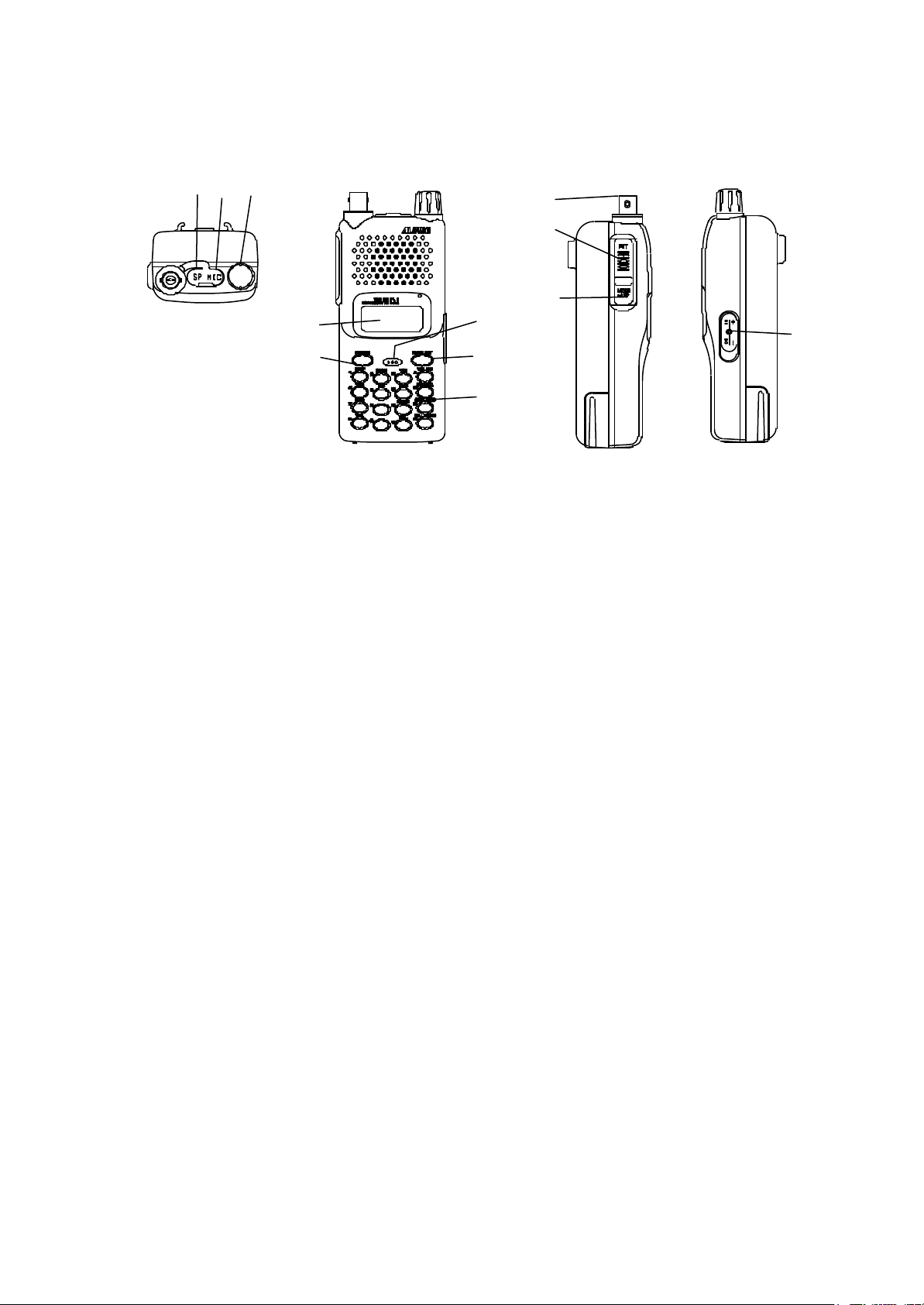
3. CONTROLS/FUNCTIONS
Top, Front, Sides and Rear View
4 3
2
1
5
7
6
8
9
10
11
1. LCD DISPLAY PANEL Refer to LCD Display section of this manual.
2. MAIN TUNING DIAL The main tuning dial/knob may be rotated in either direction to
select RX/TX frequency and volume/squelch level.
3. EXTERNAL MICROPHONE JACK When the external microphone is prefered, plug in
a 2.5mm stereo plug into this jack.
4. EXTERNAL SPEAKER JACK When the external speaker is prefered, plug in a 3.5mm mono
plug into this jack.
5. POWER SWITCH To turn on the unit, press and hold for about one second.
6. FUNCTION KEY The F key allows you to access the secondary function.
Press and hold for about two seconds ,The Set-mode function activated.
7. MIC Speak into the microphone from approximately 10cm or 3 ” distance.
8. DTMF KEYPAD During transmission, each numerical or letter key activates
one DTMF tone.
9. BNC ANTENNA CONNECTOR Connect the supplied rubber helical antenna.
When an external antenna is connected, please make sure
that your antenna has a low SWR(Standing Wave Ratio).
10. PTT(PUSH TO TALK)SWITCH To transmit, press and hold this switch. When you release it,
the unit will return to the receive mode.
11. MONITOR KEY This key is used to un-mute squelch, and a weak or intermittent signal
can be monitored regardless the squelch setting.
This also available to monitor receive frequencies when TSQ
or DCS is set.
12. DC JACK Plug in the EDC-36 cigarette lighter adapter with active noise filter
for mobile operation. The jack is polarized, the center pin is positive
and outer pin is negative.
Applying excessive or will void the radio’s warranty.
12
Page 4
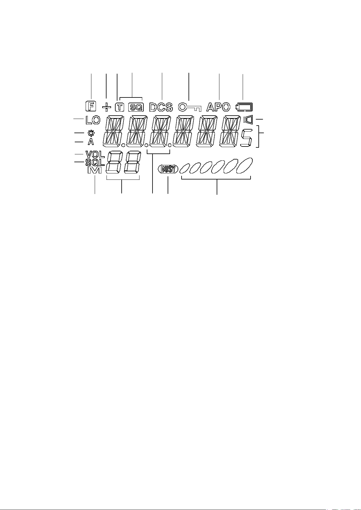
4. LCD Display
2
3
1
4
5
6
7
8
9
18
19
10
1
1
1
5
1
13 14
1. F When the F icon appears, secondary function keys may be activated.
2. + It indicated the plus or minus offset direction.
3. T It appears when the tone encoder is activated.
4. TSQ It appears when the tone squelch is activated.
5. DCS It appears when the digital code squelch is activated
6. The “ “icon appears when the key and frequency Lock is activated.
7. APO It appears when the APO (Automatic Power Off) function is activated.
8. When the voltage of the battery is dropped to be recharged,” “is disappears.
9. LO When the low power output is selected the LO icon appears.
10. VOL It appears while the volume level is adjusted by either the tuning dial.
11. SQL It appears while the squelch level is adjusted by either the tuning dial
12. 888 It indicates the TX/RX frequency, other function selected.
13. M In the Memory Mode , the M icon appears.
14. 88 While either the volume/squelch level is adjusted, and Memory channel No.
15. . decimal point
16. BUSY BUSY icon will appear when a signal is received, or squelch is unmuted.
17. 000 It indicates the received signal strength and / or the output power level.
18. * It appears when the “ SCR” function activated.
19. A It appears when the “ EXP” function activated.
20. It appears when the “ MRS” function activated.
6
17
1
20
2
Page 5

Operation Manual DJ296 Contents
5 Operation 1(Basics)
5-1 Adjusting the Volume
5-2 Adjusting the Squelch
5-3 Receiving
5-4 Transmitting
5-5 Frequency Selection
5-6 Channel Step
5-7 Shift Direction and Offset Frequency
5-8 Memory Channel Operation
5-9 CALL Channel Operation
5-10 Scanning
5-11 Output Power Switching
5-12 Key Lock Function
5-13 Tone Burst Function
5-14 Auto Power Off Function
5-15 Battery Save (BS) Function
5-16 Lamp Function
5-17 Monitor Function
5-18 Beep Function
5-19 Clock Shift Function
6 Operation 2 (Applications)
6-1 Selective Calling
6-2 Tone Encoder and Tone Squelch Function
6-3 Tone Encoder Frequency/Tone Decoder Frequency Programming
6-4 DCS (Digital Code Squelch) Function
6-5 Manual DTMF Transmitting
6-6 Auto Dialer Memory Setting
6-7 Auto Dialer Function
6-8 Redial
6-9 DTMF Time Setting
6-10 Alphanumeric Function
6-11 TOT (Time Out Timer) Function
6-12 TOT Penalty Function
6-13 BCLO (Busy Channel Lock Out) Function
7 Operation 3 (Others)
7-1 Cable Clone
7-2 Burglary Alarm Function
7-3 External Terminal Control
7-4 MRS (Mosquito Repeller Sound) Function
8 Set Mode
8-1 Setting of Set Mode
8-2 Functions Set in the Set Mode
9 Reset Function
Page 6

5 Operation 1 (Basics)
5-1 Adjusting the Volume
. [VOL] appears on LCD when VOL key is pressed, volume level is displayed.
The initial value is 00 (minimum). The volume can be increased or decreased by
rotating the dial. The maximum value is 20.
There are 21 steps from 00-20 in volume adjustment. The setting value can be
kept even while the power is off.
. When the volume point data is (00), the voice can not be heard.
Press any key (except for FUNC, MONI key) to complete the setting. The LCD
returns to the ordinal mode.
When no operation is continued for 5 seconds, the setting is completed automatically.
Then the LCD will return to the ordinal mode.
Operation The volume increases as the setting value increases.
5-2 Adjusting the Squelch
Press the SQL key, and "SQL" icon appears on the LCD. Then the squelch level is displayed.
The initial setting value is 00 (minimum). The squelch level can be increased or decreased by
rotating the dial. This value can be kept while the power is turned OFF.
. There are 21 steps from 00-20 in the squelch level.
. Press any key (except for FUNC and MONI keys) to complete the setting. Then the LCD returns to the ordinal mode.
. When no operation is continued for 5 seconds, the setting is completed automatically. Then the LCD will return to the ordinal
mode.
OperationThe squelch will be opened with the strong signal when the high value is set.
5-3 Receiving
1. Turn the power SW ON.
2. Press the VOL key to increase the volume. Rotate the dial to set to the proper
volume.
3. Press and hold the SQL key, and rotate the dial until the noise disappears.
4. Select the desired frequency. [BUSY] appears on the LCD as soon as the signal is
received in the desired frequency. Then receiving voice is heard. At the same time green RX
indicator lights up.
5-4 Transmitting
1. Select the desired frequency.
2. Press the PTT key, and the red TX indicator lights up to show the unit starts transmitting.
While pressing PTT key, speak to the internal microphone on the front of the unit
with your normal voice.
3. The transmission will be completed when the PTT key is released, then the unit
returns to the receiving mode.
Note: Press and hold the PTT key, then press MONI key to transmit the tone burst.
Note: If the PTT key is pressed outside the transmission frequency range, [OFF] will
appear on the LCD and you can not transmit.
5-5 Frequency Selection
1. Each time the V/M key is pressed, the mode is switched between VFO mode and memory mode.
2. VFO mode is selected by V/M key
[M] or [C] is not displayed on the LCD in the VFO mode.
Page 7

[UP/DOWN with channel step]
1. Rotating the dial clockwise increases frequency 1 channel step/1 click, and rotating
counterclockwise decreases the frequency 1 channel step/1 click.
[1MHz UP/DOWN]
1. Press the [F] key then rotate the dial while [F] icon is ON, the frequency increases
or decreases by 1MHz depending on the direction of the rotation.
[Keypad Direct Entry]
The frequency is set with the numerical keys of 0~9.
Setting
1. Enter the 100MHz digit.
2. Enter the 10MHz digit.
3. Enter the 1MHz digit.
4. Enter the 100kHz digit.
5. Enter the 10kHz digit.
Depending on the channel step, entry may be required to the 1kHz digit or 10kHz
digit.A confirmation tone sounds when the final digit is entered, then the setting has
been completed. The entry method of each channel step is described as follows.
Channel step Entry completion digit Entry method of for the final digit
………………………………………………………………………………………….
5.0kHz 1kHz Enter up to 1kHz digit.
10.0kHz 10kHz Enter up to 10kHz digit.
12.5kHz 10kHz Enter 10kHz digit and 1kHz digit.
0…..00.0 1 …..12.5 2 …..25.0 3 …..37.5 4……invalid
5….50.0 6 …..62.5 7…..75.0 8……87.5 9 ……invalid
15.0kHz 1kHz Enter up to 1kHz digit.
25kHz 10kHz Enter 10kHz digit, and 1kHz digit is determined.
0…00.0 2 …..25.0 5 …..50.0 7 ……75.0 Others are invalid.
30kHz 10kHz Enter 10kHz digit, and 1kHz digit is determined.
…………………………………………………………………………………………..
5-6 Channel Step
1. Press and hold the [F] key, then rotate the dial while [F] icon is ON. The frequency
increases or decreases by 1MHz depending on the direction of rotation.
In VFO mode press and hold [F] key, then press 1/STEP key while [F] icon is ON,
and the current channel step will appear.
2. Rotate the dial, the channel step toggles as follows.
….. Downward…………………………….upward…………………………………… .
…… ..STP- 5 …..STP-10…..STP-12.5 …..STP-15……STP-20……STP-25……STP-30…..
…………………………………………………………………………………………… ..
3. Press any key (except for MONI and FUNC keys) to complete the setting. The LCD returns
to the ordinal mode.
Or press and hold the FUNC key, then press the 1/STEP key to complete the setting.
4. The Lamp and MONI keys are activate even while channel step appears on the LCD.
5. In the memory mode the channel step can not be selected.
Note: When the step values are changed from 5kHz, 10kHz, 15kHz, 20kHz or
30kHz to either 12.5kHz or 25kHz, or changed in reverse, the frequency and shift
Page 8

width may be compensated.
5-7 Shift Direction and Offset Frequency
Usually the repeater is used in the duplex mode.
Namely the signal received with a certain frequency is transmitted with another frequency.
The difference between these frequencies is the offset frequency. The setting range
of the offset frequency is from 0 to 99.995MHz.
1. Press and hold the F key, then press 2/SHIFT key while [F] icon is ON. The
current offset frequency and shift direction will appear. Then each time 2/SHIFT
key is pressed, the shift direction toggles as follows:
…….. -1.60……. +1.60……..OST-OF………
……………………………………………….
2. While shift frequency is d isplayed, rotating the dial clockwise increases the
frequency by 1 channel step/1 click and rotating the dial counterclockwise decreases
the frequency by 1 channel step/1 click.
3. Press and hold the F key, then rotate the dial. The frequency increases or
decreases by 1MHz depending on the rotating direction.
Press any key (except for MONI and FUNC keys) to complete the setting. The LCD returns to
the ordinal mode.
4. The Lamp and MONI keys are activate while shift frequency is displayed on the LCD.
Also the setting can be completed by pressing 2/STEP key while holding the FUNC key.
5-8 Memory Channel Operation
This unit is provided with 160 memory channels (0 - F9 ) and one call channel (C).
The memory can not be increased.
(1) Calling of memory channel
1. Press V/M key, and [M] will appear on the LCD indicating the unit enters the
memory mode. [M] icon flashes to show the CH's memory has not been programmed,
and the VFO frequency is displayed.
2. Rotating the dial clockwise increases the memory channel number by 1 channel.
Rotating the dial counterclockwise decreases the memory channel number by 1 channel.
(2) Programming a memory channel
Memory Programming
1. In VFO mode select the desired frequency, then set Shift and Tone Function as necessary.
2. Press V/M key to enter the memory mode.
3. Rotate the dial to select the desired memory channel number.
4. The unprogrammed memory CH's number flashes.
5. Press and hold the FUNC key, then press the MW key while FUNC icon is ON. A
beep sounds indicating the completion, and the VFO frequency has been
programmed in the selected memory channel.
*If a memory CH whose memory has been programmed is selected at 4. in the
operation of 5. the memory will be erased and [M] will start flashing.
6. When CH-C is selected, the CALL channel is also reprogrammed.
[C] will not flash.
The content of the memory should be erased beforehand to be reprogrammed.
(3) Erasing of a memory channel
1. Press the V/M key to select the memory mode.
2. Rotate the dial to select the desired memory channel number.
Page 9

When the memory channel is programmed, [M] appears on the LCD.
3. Press and hold the FUNC key, then press MW key while [F] icon is ON. A beep
sounds, and the programmed frequency will be erased. Then [M] starts flashing.
4. While [M] is flashing, the erased memory is still displayed on the LCD.
Press and hold the F key then press the MW key again, the erased memory can be
recovered. If CH or mode had been changed, the recovery is not available.
(4) Programmable Data
The followings can be programmed in the memory channels 0 - F9 and the CALL channel:
. Frequency
. Shift frequency
. Shift direction(+/-)
. Tone encoder frequency
. Tone decoder frequency
. Tone encoder/decoder setting
. DCS code
. DCS setting
. Skip CH setting
. Busy Channel Lock Out (BCLO)
. TX power H/L
. Battery save setting
. Clock shift setting
5-9 CALL Channel Operation
The initial setting is 223.500MHz.
(1) Calling the CALL channel
1. Press the CALL key, and CALL channel is called. [C] (Right justification) appears
on the LCD and the unit enters the CALL mode.
In CALL mode the frequency and memory channel number can not be changed by dialing.
The offset setting and tone setting can be changed and operated temporarily.
2. Press the CALL key again to return to VFO mode or memory mode.
Also pressing the V/M key causes to return to the previous VFO mode or memory mode.
3. Scanning can not be done in the CALL mode.
(2) Changing the Frequency of the CALL Channel
The CALL channel is allocated as a memory channel. So when you change the
CALL frequency and other settings, call the memory channel C from the VFO or
memory mode to reprogram.
Note: CALL channel frequency can be changed but can not be erased.
5-10 Scanning
This function varies the frequency automatically to search for the signals being received.
Timer Scan (After pausing the scan, the frequency goes to the next channel when 5
seconds elapsed even if a signal is picked up.)
Busy Scan (After pausing the scan, the frequency goes to the next channel when the
signal is disappeared.)
While scanning 1. the rotary encoder determines the direction of the channel UP/DOWN.
2. Monitor function is activate.
. Scanning can be released by pressing any key (except for the MONI key).
. The last direction of UP/DOWN is defined as the scan direction.
Page 10

(1) VFO SCAN
1. Press the V/M key to enter VFO mode.
2. Press the SCAN key to start scanning.
The decimal point of the frequency on the LCD starts flashing to indicate the
scanning is started.
The unit scans by a channel step to the last direction of operation.
3. Rotate the dial clockwise to scan upward and counterclockwise to scan downward.
VFO SCAN covers all receiving frequency range for scanning.
4. Press any key (except for MONI key) to stop scanning.
(2) Memory Scan
1. Press the V/M key to enter the memory mode.
2. Press the SCAN key to start memory scanning.
3. Rotate the dial clockwise to scan upward and counterclockwise to scan downward.
The memory scan scans only programmed channels.
4. Press any key (except for MONI key) to stop scanning.
The scanning pauses at the channel or frequency where a signal is picked up, then
resumes when the signal is dropped.
(3) Skip Channel Setting
The memory channel that is programmed in the skip channel will be skipped when
the memory scanning.
In the memory mode press and hold the function key, then press C/SKIP while [F]
icon is ON, the selecting memory channel is programmed to the skip channel.
The skip channel is determined at this point without memory programming.
The skip channel is released with the same operation.
. The 10MHz decimal point of the memory channel will appear when the skip
channel is programmed to the channel.
5-11 Output Power Switching
The output power can be switched.
Press and hold the F key, then press 5/H/L key while [F] icon is ON. Output power
can be switched between High and Low.
When the power is LOW, "LO" will appear. Nothing is displayed when the power is High.
The initial setting is LOW power.
RF meter shows 3 dots in LOW power, and 6 dots in HIGH power.
. H/L power switching can not be done while transmitting.
5-12 Key Lock Function
Press and hold the F key, then press B/KL key to set the key lock.
. In key lock mode only PTT, LAMP, MONI, VOL, SQL and TONE BURST/MONI
keys are activate.
. In the key lock mode [ KEY mark] appears.
Press and hold the F key, then press B/KL key while [F] icon is ON to release the key lock mode.
5-13 Tone Burst Function
This is the required function to access the European repeater.
. Press and hold the PTT key then press the MONI key, the tone burst signal will be transmitted.
The initial value of the tone frequency is 1750Hz, and it is changeable in the set mode.
Page 11

When tone and DCS are set, the signal will be transmitted with tone frequency and
DCS code.
5-14 Auto Power Off Function
The function prevents the battery from consuming when you forget to turn off the power switch.
(1) Setting
Press and hold the F key, then press 6/APO key while F icon is ON. [APO] appears
on the LCD and the auto power off function is programmed.
. The initial setting is OFF.
. To release the APO, press and hold the F key then press 6/APO key while F is ON .
(2) APO Operation
If no operation is performed for more than 30 minutes while APO icon is ON, a beep
sounds and the transceiver will be turned off.
Turn the power switch ON again to resume the power.
. APO function is not prolonged by picking up a signal but the key operation only.
5-15 Battery Save (BS) Function
This function saves the current consumption while waiting for a signal for the long
use of the battery.
. ON/OFF is switched in the set mode.
. The factory's initial setting is ON.
. The battery save function is set to OFF automatically while scanning.
. When no signal and no operation are continued for 5 seconds, the battery save
function will be resumed automatically.
When a signal is received or an operation is performed, battery save function is
released temporarily.
5-16 Lamp Function
. Press and hold the F key, then press MONI key while F icon is ON. The LCD
backlight will be turned on.
When no operation is continued for 5 seconds, the lamp will be turned off automatically.
If you press any key except for the LAMP key while the lamp is on, the lamp goes
out 5 seconds after the last key operation.
Press and hold the MONI key, then turn the power ON, and the lamp will be always ON.
Press and hold the F key then press MONI key, the lamp can be turned ON/OFF
even you set the lamp to be always ON.
The lamp will be always ON even if you turn the power OFF and ON when the lamp
is set to be always ON.
5-17 Monitor Function
The squelch operation is released regardless of the setting mode of SQL only while
pressing the MONI key, and a sound is heard from the speaker.
. The weak signal under the threshold level can be heard.
5-18 Beep Function
This function produces a beep during operation.
. The beep can be muted in the set mode.
5-19 Clock Shift Function
Page 12

In the unlikely event that CPU clock noise is present on a particular operating
frequency programmed into the radio, you can shift the CPU clock frequency to avoid
the CPU clock noise, which normally is so weak that it is inaudible even if the radio is
tuned exactly to its frequency.
CPU clock can be shifted in the set mode.
6 Operation 2 (Applications)
6-1 Selective Calling
When you communicate with the specific station, tone squelch function or DCS
function is useful.
The tone squelch function allows to transmit one of 39 kinds of sub-audible tones
with a voice. Then the voice can be heard when the sub-audible tones match at
the receiving side.
The DCS function allows to transmit one of 104 kinds of digital codes with a voice.
Then the voice can be heard when the programmed codes match at the receiving
side.
. The tone squelch function and DCS function can not be used at the same time.
6-2 Tone Encoder and Tone Squelch Function
1. Press and hold the F key, then press 4/TSQL key while F icon is ON, the current
mode and tone frequency are displayed. Each time 4/TSQ key is pressed, the
mode is switched as follows:
T T/SQ
… 88.5 ……. 88.5 … TCS-OF …..
……………………………………
. Only T appears indicating the encoder function setting only is allowed.
. T SQ appears indicating encoder/decoder function setting.
. While the tone frequency is displayed, the lamp function and MONI key are
available.
Press any key (except for FUNC and MONI keys) to complete the setting. The
LCD returns to the ordinal mode with T/TSQ indication.
2. While the tone frequency is displayed, rotate the dial clockwise to increase or
counterclockwise to decrease the tone frequency. The tone frequency for use can be
selected from 39 reference tones described below.
--------------------------------------------------------------------------------------------------------------------
67.0 69.3 71.9 74.4 77.0 79.7 82.5 85.4 88.5 91.5
94.8 97.4 100.0 103.5 107.2 110.9 114.8 118.8 123.0 127.3
131.8 136.5 141.3 146.2 151.4 156.7 162.2 167.9 73.8 179.9
186.2 192.8 203.5 210.7 218.1 225.7 233.6 241.8 250.3
----------------------------------------------------------------------------------------------------------------------
3. Press any key (except for FUNC and MONI keys) to complete the setting. The
LCD returns to the frequency indication mode.
6-3 Tone Encoder Frequency/Tone Decoder Frequency Programming
The tone encoder frequency and tone decoder frequency can be programmed
respectively to each memory CH.
Page 13

Changing both of tone encoder/tone decoder frequencies
1. Set the tone encoder in the tone squelch setting mode. (T icon is ON.)
Change the tone encoder frequency with dialing, then the setting is completed.
2. When memory is programmed in this mode, the current tone frequency will be
programmed to both of encoder frequency and decoder frequency.
Changing the tone decoder frequency only
1. The tone squelch is programmed in the tone squelch setting mode. (T.SQL icon is ON.)
2. Change the tone decoder frequency with dialing, then the setting is completed.
3. When memory is programmed in this mode, the current tone frequency will be
programmed as the decoder frequency. In this case, encoder frequency is not reprogrammed.
Tone squelch operation
The squelch is released when received tone frequency accords with the rogrammed tone frequency.
6-4 DCS (Digital Code Squelch) Function
DCS setting
Press and hold the F key, then press 7/DCS key while F icon is ON. [DCS] icon is
turned ON and DSQ code appears. The initial mode is [023]. Each time you
press the 7/DCS key, the mode is switched.
DCS
…….. 023 ……… DCS-OF …..
…………………………………
The lamp function and MONI key are available while indicating the code on the LCD.
Press any key (except for FUNC and MONI keys) to complete the setting. The
LCD returns to the ordinal mode with DCS indication.
DCS code changing
[When you change the DCS code]
1. Set the DCS code in the DCS code setting mode. (DCS icon is ON.)
2. Change the DCS code with dialing, then the setting is completed.
3. When the memory is programmed in this mode, the current tone frequency will be
programmed to both of encoder frequency and decoder frequency.
DCS operation
The squelch will be released when the received code is accordant with programmed
code.
6-5 Manual DTMF Transmitting
This function allows you to transmit DTMF code manually by pressing one of 16 keys
during transmitting.
1. Press and hold the PTT key, then press one of 16 keys.
2. DTMF code that is accordant with one of 16 keys will be transmitted.
. Manually transmitted DTMF code is stored until 16 digits automatically, and it will
be redialed when necessary as well as the auto dialer.
6-6 Auto Dialer Memory Setting
The function stores the DTMF code that is transmitted by the auto dialer to the memory.
There are 16 kinds of codes in DTMF with maximum 16 digits. They are entered with 16 keys.
. There are 9 channels of 1CH~9CH, and the channel can be selected by dialing.
Auto dialer code setting
1. Press and hold the F key, then press 9/ dial M key, the unit enters the dialer setting mode.
Page 14

6 digits are displayed, and nothing appears at first.
2. Select the dialer memory NO. with the dial.
3. For example, when you input 1 2 3 4 5 6 7 8 9, the LCD displays as shown below:
[ 1] - [ 1 2] - [ 1 2 3 ] [ 1 2 3 4 ] - [ 1 2 3 4 5 6 ] - [ 2 3 4 5 6 7 ] - [ 3 4 5 6 7 8 ] - [ 4 5 6 7 8 9 ]
4. Press and hold the F key, then press 0 key while F icon is ON, pause can be set
instead of the code. Pause is indicated by [ - ]. Entering a pause puts a gap
between transmission of codes.
Press and hold the F key, then rotate the dial while F icon is ON, and the display
scrolls within the range in which the codes are programmed.
5. If you enter the wrong code, press and hold the F key, then press C/CALL(SKIP) to clear.
6. Press the PTT key to complete the setting.
. The auto dialer can be programmed up to 16 digits including the pause.
6-7 Auto Dialer Function
This function automatically sends pre-programmed DTMF codes.
Operation in receiving mode
1. In receiving mode press D/A dial key, [DIAL] appears on the LCD and a
confirmation tone sounds.
Press a key of 1-9, the dialer memory that is accordant with the key No. (max. 16
digits) will be output from the speaker automatically.
. In this case the code is not sent.
If nothing is stored in the memory, a beep tone sounds indicating that the operation
is invalid when you press a key of 1-9.
Operation in transmitting mode
1. Press F key in the transmitting mode. [DIAL] appears on the LCD.
2. Press a key of 19, the dialer memory that is accordant with the key No. (max. 16
digits) will be transmit automatically.
. In this case, a beep tone does not sound if you press the unprogrammed key.
6-8 Redial
This function transmits the last transmitted DTMF codes again.
1. Press D key in receiving mode. A reception tone will sound.
2. Press 0 key. If the code to be redialed is not stored, a beep tone sounds indicating
the operation is invalid when 0 key is pressed.
The last transmitted DTMF codes (either of auto dialer codes or manually
transmitted DTMF code) will be output automatically from the speaker. In this
case the codes are not sent.
Press and hold the F key, then press 0 key in transmitting mode, and redialing
becomes available. In this case the code is sent.
6-9 DTMF Time Setting
This function changes the settings of the wait time of auto dialer, burst/pause time
and burst time of the first digit.
. The settings can be changed in the set mode.
DTMF WAIT time
When the DTMF code is transmitted using the auto dialer, the code transmission
starts after the programmed WAIT time elapsed. The initial setting is 100ms.
DTMF burst/Pause time
Page 15

1. When the DTMF code is transmitted using the auto dialer, the code is transmitted
with programmed burst/ pause time. The initial setting is 60ms.
DTMF first digit's burst time
2. When the DTMF code is transmitted using the auto dialer, the code will be
transmitted at the programmed first digit burst time. The initial setting is 60ms.
3. WAIT time cannot be changed while CH is displayed.
6-10 Alphanumeric Function
In the memory mode this function allows to display optional alphabet, number or code
instead of frequency.
Alphanumeric function setting
1. In memory mode select the desired channel.
2. Press and hold the F key, then press the D/NAME key while F icon is ON.
3. Flashing [A ] will appear on the LCD.
4. Rotate the dial to select the desired letter.
5. Press [D] key, the flashing will be stopped indicating the letter is stored.
6. The same letter flashes on the right of the stored letter waiting to be stored.
7. Press the [D] key to store in the memory. (Store desired letters in turn.)
8. If you press the C key while storing, the stored letters will be erased.
9. Press the PTT key to complete the operation.
Operation of alphanumeric function
1. When the unit enters the memory mode, if the channel is programmed
alphanumeric function, the frequency display part will be showed with the stored
alphanumeric letters. (The CH number will be displayed as it was.)
Press F key, and the frequency will appear for 5 seconds on the LCD. (If any key is
pressed within 5 seconds, the LCD returns to the display with the alphanumeric
letters.)
6-11 TOT (Time Out Timer) Function
TOT setting
1. Press and hold the F key, then press the 3/TOT key while F icon is ON.
[T-OFF] will appear on the LCD.
2. The display is toggled as follows by dialing, and the setting of TOT will be changed.
3. The number indicated on *** is the current Time Out Time.
4. Change the TOT time by rotating the dial. The TOT time can be programmed up to
max. 450 seconds.
……downward upward …..
….. OFF….. 30 …..60 …..90 ……………450…..
………………………………………………… ..
Press any key (except for FUNC and MINI keys) to complete the setting. The
LCD will return to the ordinal mode.
Operation of TOT
1. If the continuous transmission time is over the programmed time, a beep sounds 5
seconds before the time is up. Then the transceiver enters the receiving mode
automatically.
2. In this case, unless the PTT key is turned OFF, the next transmission is deactivate.
(When the TOT Penalty is set, transmission can not be done even if you turn OFF
the PTT then ON again within the programmed time.)
Page 16

6-12 TOT Penalty Function
When the transmission is completed by the TOT function, the transmission will be
inhibited within the programmed TOT Penalty time. The transmission is inhibited
during the penalty time.
1. TOT Penalty function and its penalty time can be programmed in the set mode.
If the PTT key is pressed during the TOT Penalty time, an alarm tone will sound.
2. The penalty will be cancelled if you keep holding down the PTT key until TOT
expires and also TOT Penalty time elapses.
5-13 BCLO (Busy Channel Lock Out) Function
BCLO disables the transmission according to the receiving condition.
. BCLO function can be turned ON/OFF in the set mode.
. When the BCLO is set, transmission is possible only in following cases and
transmission is inhibited in the other cases.
If PTT key is pressed while the transmission is inhibited, an alarm tone will sound.
In this time transmission is deactivate.
1. No signal is picked up. (BUSY disappears.)
2. The tone frequencies match and the squelch is opened while using the tone squelch.
3. The codes match and the squelch is opened while using DCS.
7 Operation 3 (Others)
7-1 Cable Clone
With an interface cable the entire memory channel data of one transceiver can be
transferred and copied to another transceiver.
Connection
As shown in the figure, connect the external speaker jacks of two transceivers;
transmitting side and receiving side, with 3.5mm stereo plug cord on the market.
. Be sure to turn the power OFF at cable connecting.
. Please use the directly connected cable including no resistors inside. Be careful not
to use the cable that contains any resisters.
Operation of data receiving side
1. Turn the power ON. (The unit enters the data receiving mode.)
2. When the data is sent from the transmitting side, "LD ***" appears on the LCD.
Then the data transfer is started.
3. When the transfer is completed, "PASS" is appears on the LCD.
Turn the power OFF. If the data transfer is failed, "PASS" does not appear on the LCD.
Operation of data transmitting side
1. Turn the power ON.
2. Press and hold the MON key, then press the PTT key 3 times, "CLONE" will
appear on the LCD. The unit enters the Clone mode.
3. Press the PTT key, "SD 000" appears on the LCD. The internal memory channel
data is transferred to the other transceiver.
4. The transfer is completed, "PASS" appears on the LCD.
5. Turn the power OFF, and the Clone mode is released.
Page 17

If data transfer is failed, "PASS" does not appear on the LCD. Try again from the first.
7-2 Burglary Alarm Function
If someone tries to steal your transceiver, an alarm goes off from the speaker.
Setting Be sure to set the battery pack.
1. Plug the external DC power plug cord to the car battery, etc.
2. Set to SCR-ON in the set mode.
3. Turn off the power switch of the unit.
. To release the setting, set to SCR-OF in the set mode.
Operation
. If someone unplug the power code to bring out your transceiver, an alarm goes off.
. Once the alarm goes off, it does not stop until you remove the battery pack.
. Set the battery pack and turn the power ON to release this function in the set mode.
Please set to SCR-OF in the normal operation.
7-3 External Terminal Control
"5V" is output from MIC jack terminal when the speaker is ON.
. Set to EXP-ON in the set mode.
. When receiving (The tone and code should match when the TSQ/DCS is set),
DC5V(5mA max.) is output from the center terminal of MIC stereo jack.
. Set to EXP-OF in the set mode to cancel this function.
The optional VOX MIC, etc. (EME-12, EME-13, EME-15) can not be used at EXP- ON.
7-4 MPS (Mosquito Repel Sound) Function
This function generates the supersonic that repels mosquitos from the speaker.
. Set to MPS-ON in the set mode.
. The ordinal operation is available when MPS is set.
. As the unit always generates supersonic when MPS is set, battery operating time
may become shorter.
. Set to MPS-OF to cancel the function in the set mode.
8 Set Mode
The transceiver can program the various function using the set mode.
8-1 Setting of the Set Mode
1. Press the FUNC key for more than 2 seconds, the unit enter the set mode.
2. Press the MONI key to select the menu. The monitor does not work here.
3. Rotate the dial to change the setting contents.
4. Press any key (except for the MONI key) to complete the setting. The LCD
returns to the ordinal mode.
8-2 Functions Set in the Set Mode
The following functions can be programmed in the set mode.
Here is the explanation of each function.
[No.1] Battery Save Function ON/OFF
Page 18

1. [BS-ON] appears on the LCD.
2. Rotate the dial, and the display toggles as shown below. Then ON and OFF are
switched repeatedly.
..downward upward…..
……BS-ON - BS-OF ……….
………………………………….
[No.2] Scan Type Selection
1. [TIMER] appears on the LCD.
2. Rotate the dial, and the display toggles as shown below. The scan types are
switched repeatedly.
.downward upward…..
…..TIMER …..BUSY …..
…………………………..
[No.3] Beep Tone ON/OFF
1. [BEP-ON] appears on the LCD.
2. Rotate the dial to set to [BEP-OF].
3. Each time the dial is rotated, ON and OFF are switched repeatedly.
[No.4] Tone Burst Frequency Setting
1. [1750] appears on the LCD.
2. Rotate the dial, and the display toggles as shown below. Then the tone burst
frequency will be changed.
…… Downward Upward……
……… 1750……. 2100…… 1000….. 1450……
…………………………………………………
[No.5] Clock Shift Setting
1. [SFT-OF] appears on the LCD.
2. Rotate the dial, and the display toggles as shown below. Then the setting of the
CLOCK will be changed.
….. Downward…… Upward…… .
………SFT-OF… SFT-ON………..
…………………………………… .
[No.6] Busy Channel Lock Out Setting
1. [BCL-OF] appears on the LCD.
2. Rotate the dial, and the display toggles as shown below. Then the setting of the
BCLO will be changed.
…… Downward……Upward ……… .
……… .BCL-OF……BCL-ON……….
……………………………………… ...
[No.7] TOT Penalty Time
1. [TP-OFF] appears on the LCD.
2. Rotate the dial, and the display toggles as shown below. The setting of TOT
penalty will be changed.
3. ** shows the current TOT penalty time.
The initial setting is 0 second. [TP-OFF] appears on the LCD.
4. Rotate the dial to change the TOT penalty time.
….. Downward…….Upward…………
…… . TP-0FF….. TP-1…… TP-4…… TP-15……… .
……………………………………………………… .
Page 19

The setting is available up to max. 15 seconds.
[No.8] DTMF WAIT time
1. [DWT-01] appears on the LCD.
2. Rotate the dial, and the display toggles as shown below. Then the DTMF WAIT
time will be changed.
3. ** shows the current DTMF WAIT time.
The initial setting is 0.1 second, and [DWT-01] appears on the LCD.
4. Rotate the dial to change the DTMF WAIT time.
……Downward………………… ..Upward……………
…..DWT-01….DWT-04……DWT-07….. DWT-10 ……
…………………………………………………………..
[No.9] DTMF Burst/Pause Time
1. [DP-60] appears on the LCD.
2. Rotate the dial, and the display toggles as shown below. Then the DTMF
burst/pause time will be changed.
3. ** shows the current DTMF burst/pause time.
The initial setting is 60 msec, and [DP-60] appears on the LCD.
4. Rotate the dial to change the DTMF burst/pause time.
…….Downward……………Upward………………...
…… ..DP-60 …..DP-80 ……DP-160……DP-200……..
…………………………………………………………
[No.10] The First Digit Burst Time of DTMF
1. [DB-60] appears on the LCD.
2. Rotate the dial, and the display toggles as shown below. Then the first digit of
DTMF burst time will be changed.
3. ** shows the current the first digit of DTMF burst time.
The initial setting is 60 msec, [DB-60] appears on the LCD.
4. Rotate the dial to change the first digit of DTMF burst time.
….Downward……Upward…………………………..
…..DB-60……DB-80…… DB-160….. DB-200……
………………………………………………………
[No.11] Burglary Alarm Function
1. [SCR-OF] appears on the LCD.
2. Rotate the dial, and the display toggles as shown below. Then the ON/OFF of the
burglary alarm function is switched.
………..Downward…………Upward……………
………..SCR-OF……….. SCR-ON………………
…………………………………………………….
[No.12] External Terminal Controller Output
1. [EXP-OF] appears on the LCD.
2. Rotate the dial, and the display toggles as shown below. The ON/OFF of the
controller output to external terminal will be switched repeatedly.
……Downward……Upward………… .
……….EXP-OF…… EXP-ON……….
…………………………………………
[No.13] Mosquito Repel Sound Function
1. [MRS-OF] appears on the LCD.
2. Rotate the dial, and the display toggles as shown below. The ON/OFF of the
Mosquito repel sound will be switched repeatedly.
…… Downward…….Upward………… ..
Page 20

…………MRS-OF …..MRS-ON………..
……………………………………………
9 RESET Function
Press and hold the F key, then turn on the power. The unit returns to the factory's default setting.
……………………………………………………………………………………………………..
VFO frequency 223.500MHz
CALL frequency 223.500MHz
Memory channel a blank
SHIFT setting none
SHIFT frequency 1.6MHz
Channel step 5kHz
……………………………………………………………………………………………………..
. Press and hold the F key, the LCD's all segments are turned ON. When you
release the F key, the reset will be performed.
Press and hold the F key, then turn the power OFF. In this case the reset function
will not be performed. This function is useful to check whether the LCD's all
segment lights or not without the RESET function.
Page 21

 Loading...