

Page 1

Service Manual
DJ-175
Specifications
Circuit Description
Parts List
Exploded View
PC Board View
Adjustment
Schematic Diagram
Block Diagram
ALINCO, INC
Page 2
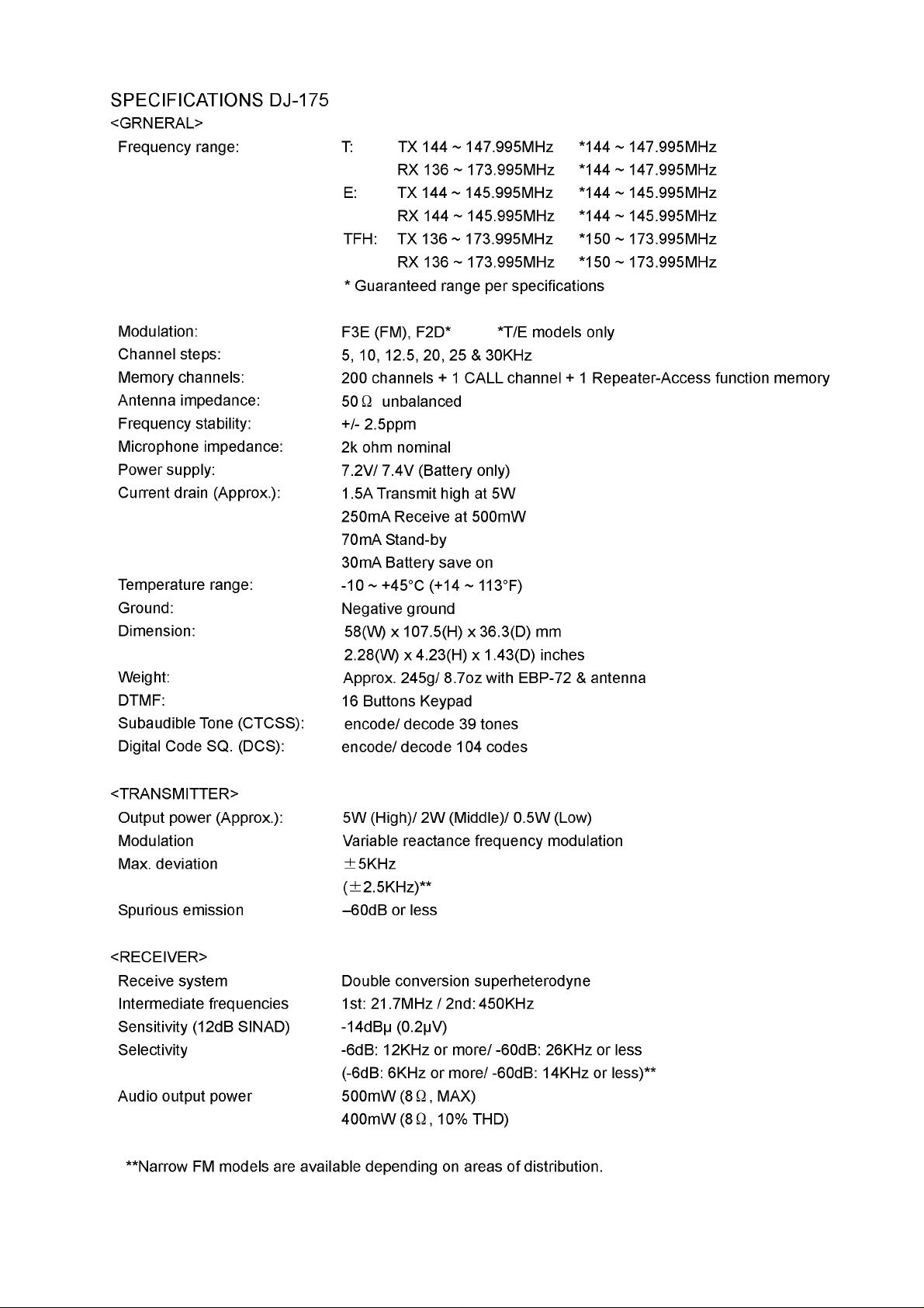
SPECIFICATIONS DJ-175
<GRNERAL>
Frequency range:
T: TX 144 ~ 147.995MHz *144 ~ 147.995MHz
RX 136 ~ 173.995MHz *144 ~ 147.995MHz
E: TX 144 ~ 145.995MHz *144 ~ 145.995MHz
RX 144 ~ 145.995MHz *144 ~ 145.995MHz
TFH: TX 136 ~ 173.995MHz *150 ~ 173.995MHz
RX 136 ~ 173.995MHz *150 ~ 173.995MHz
* Guaranteed range per specifications
Modulation:
Channel steps:
Memory channels:
Antenna impedance:
Frequency stability:
Microphone impedance:
Power supply:
Current drain (Approx.):
Temperature range:
Ground:
Dimension:
Weight:
DTMF:
Subaudible Tone (CTCSS):
Digital Code SQ. (DCS):
F3E (FM), F2D* *T/E models only
5, 10, 12.5, 20, 25 & 30KHz
200 channels + 1 CALL channel + 1 Repeater-Access function memory
50 Q unbalanced
+/- 2.5ppm
2k ohm nominal
7.2V/ 7.4V (Battery only)
1.5A Transmit high at 5W
250mA Receive at 500mW
70mA Stand-by
30mA Battery save on
-10 ~ +45°C (+14 ~ 113°F)
Negative ground
58(W) x 107.5(H) x 36.3(D) mm
2.28(W) x 4.23(H) x 1.43(D) inches
Approx. 245g/ 8.7oz with EBP-72 & antenna
16 Buttons Keypad
encode/decode 39 tones
encode/decode 104 codes
<TRANSMITTER>
Output power (Approx.):
Modulation
Max. deviation
Spurious emission
<RECEIVER>
Receive system
Intermediate frequencies
Sensitivity (12dB SINAD)
Selectivity
Audio output power
**Narrow FM models are available depending on areas of distribution.
5W (High)/ 2W (Middle)/ 0.5W (Low)
Variable reactance frequency modulation
±5KHz
(±2.5KHz)**
-60dB or less
Double conversion superheterodyne
1st: 21.7MHz / 2nd: 450KHz
-14dB|j (0.2jV)
-6dB: 12KHz or more/ -60dB: 26KHz or less
(-6dB: 6KHz or more/ -60dB: 14KHz or less)**
500mW (8 Q, MAX)
400mW (8 Q , 10% THD)
Page 3
CIRCUIT DESCRIPTION
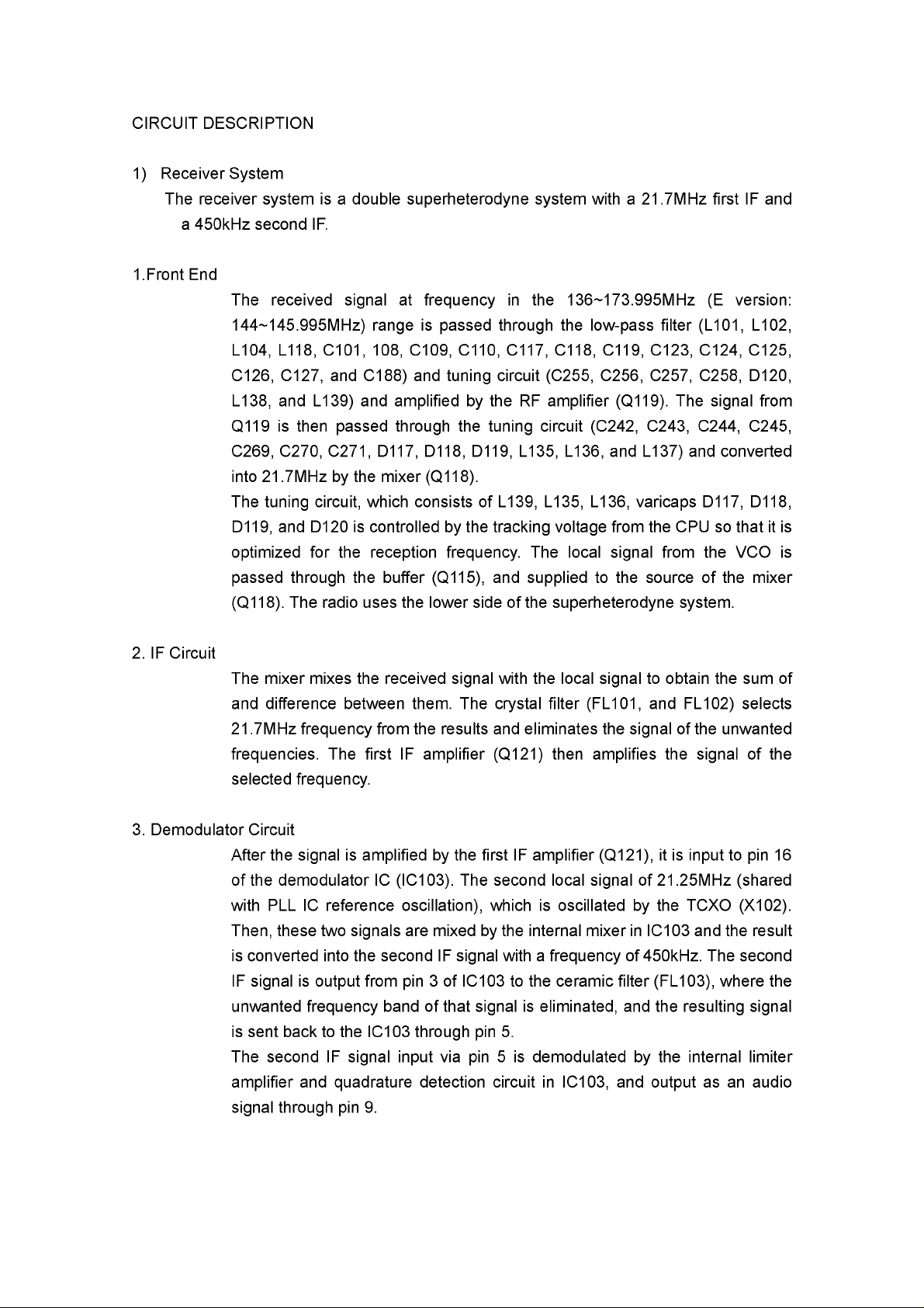
1) Receiver System
The receiver system is a double superheterodyne system with a 21.7MHz first IF and
a 450kHz second IF.
1.Front End
The received signal at frequency in the 136~173.995MHz (E version:
144~145.995MHz) range is passed through the low-pass filter (L101, L102,
L104, L118, C101, 108, C109, C110, C117, C118, C119, C123, C124, C125,
C126, C127, and C188) and tuning circuit (C255, C256, C257, C258, D120,
L138, and L139) and amplified by the RF amplifier (Q119). The signal from
Q119 is then passed through the tuning circuit (C242, C243, C244, C245,
C269, C270, C271, D117, D118, D119, L135, L136, and L137) and converted
into 21.7MHz by the mixer (Q118).
The tuning circuit, which consists of L139, L135, L136, varicaps D117, D118,
D119, and D120 is controlled by the tracking voltage from the CPU so that it is
optimized for the reception frequency. The local signal from the VCO is
passed through the buffer (Q115), and supplied to the source of the mixer
(Q118). The radio uses the lower side of the superheterodyne system.
2. IF Circuit
The mixer mixes the received signal with the local signal to obtain the sum of
and difference between them. The crystal filter (FL101, and FL102) selects
21.7MHz frequency from the results and eliminates the signal of the unwanted
frequencies. The first IF amplifier (Q121) then amplifies the signal of the
selected frequency.
3. Demodulator Circuit
After the signal is amplified by the first IF amplifier (Q121), it is input to pin 16
of the demodulator IC (IC103). The second local signal of 21.25MHz (shared
with PLL IC reference oscillation), which is oscillated by the TCXO (X102).
Then, these two signals are mixed by the internal mixer in IC103 and the result
is converted into the second IF signal with a frequency of 450kHz. The second
IF signal is output from pin 3 of IC103 to the ceramic filter (FL103), where the
unwanted frequency band of that signal is eliminated, and the resulting signal
is sent back to the IC103 through pin 5.
The second IF signal input via pin 5 is demodulated by the internal limiter
amplifier and quadrature detection circuit in IC103, and output as an audio
signal through pin 9.
Page 4
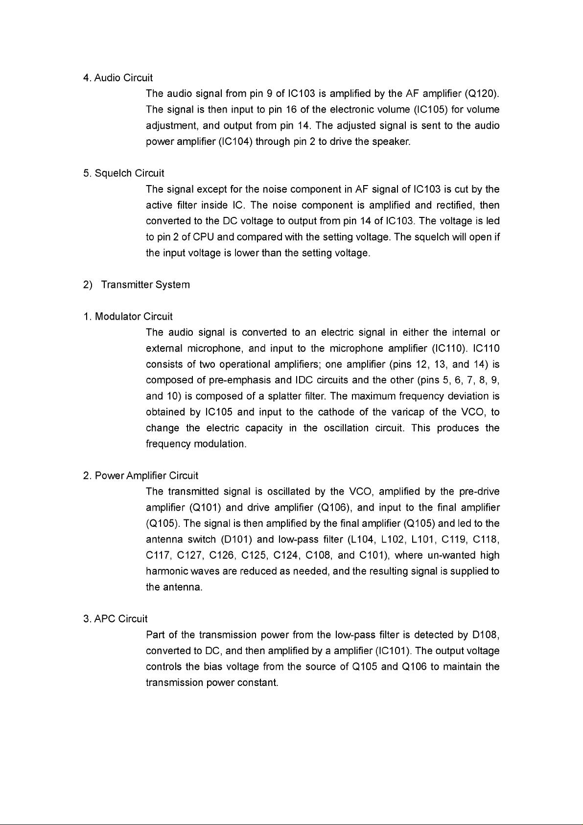
4. Audio Circuit
The audio signal from pin 9 of IC103 is amplified by the AF amplifier (Q120).
The signal is then input to pin 16 of the electronic volume (IC105) for volume
adjustment, and output from pin 14. The adjusted signal is sent to the audio
power amplifier (IC104) through pin 2 to drive the speaker.
5. Squelch Circuit
The signal except for the noise component in AF signal of IC103 is cut by the
active filter inside IC. The noise component is amplified and rectified, then
converted to the DC voltage to output from pin 14 of IC103. The voltage is led
to pin 2 of CPU and compared with the setting voltage. The squelch will open if
the input voltage is lower than the setting voltage.
2) Transmitter System
1. Modulator Circuit
The audio signal is converted to an electric signal in either the internal or
external microphone, and input to the microphone amplifier (IC110). IC110
consists of two operational amplifiers; one amplifier (pins 12, 13, and 14) is
composed of pre-emphasis and IDC circuits and the other (pins 5, 6, 7, 8, 9,
and 10) is composed of a splatter filter. The maximum frequency deviation is
obtained by IC105 and input to the cathode of the varicap of the VCO, to
change the electric capacity in the oscillation circuit. This produces the
frequency modulation.
2. Power Amplifier Circuit
The transmitted signal is oscillated by the VCO, amplified by the pre-drive
amplifier (Q101) and drive amplifier (Q106), and input to the final amplifier
(Q105). The signal is then amplified by the final amplifier (Q105) and led to the
antenna switch (D101) and low-pass filter (L104, L102, L101, C119, C118,
C117, C127, C126, C125, C124, C108, and C101), where un-wanted high
harmonic waves are reduced as needed, and the resulting signal is supplied to
the antenna.
3. APC Circuit
Part of the transmission power from the low-pass filter is detected by D108,
converted to DC, and then amplified by a amplifier (IC101). The output voltage
controls the bias voltage from the source of Q105 and Q106 to maintain the
transmission power constant.
Page 5
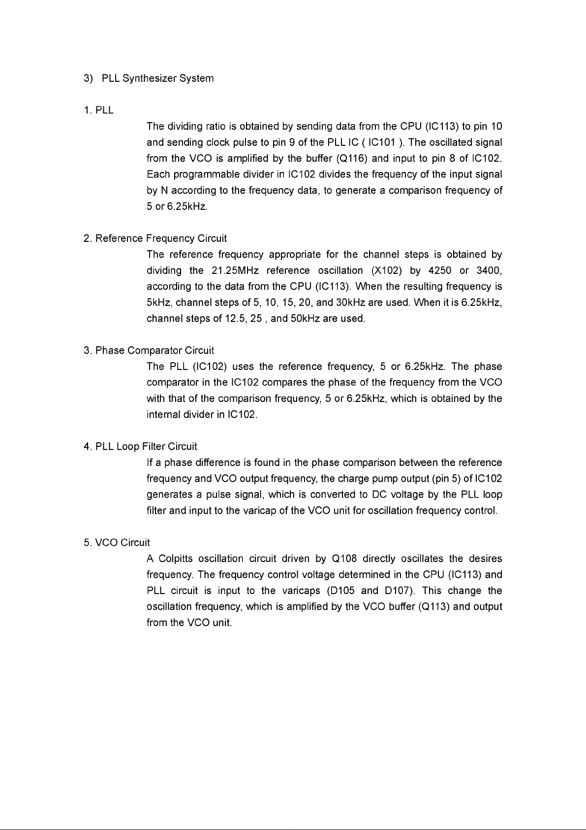
3) PLL Synthesizer System
1. PLL
The dividing ratio is obtained by sending data from the CPU (IC113) to pin 10
and sending clock pulse to pin 9 of the PLL IC ( IC101 ). The oscillated signal
from the VCO is amplified by the buffer (Q116) and input to pin 8 of IC102.
Each programmable divider in IC102 divides the frequency of the input signal
by N according to the frequency data, to generate a comparison frequency of
5 or 6.25kHz.
2. Reference Frequency Circuit
The reference frequency appropriate for the channel steps is obtained by
dividing the 21.25MHz reference oscillation (X102) by 4250 or 3400,
according to the data from the CPU (IC113). When the resulting frequency is
5kHz, channel steps of 5, 10, 15, 20, and 30kHz are used. When it is 6.25kHz,
channel steps of 12.5, 25 , and 50kHz are used.
3. Phase Comparator Circuit
The PLL (IC102) uses the reference frequency, 5 or 6.25kHz. The phase
comparator in the IC102 compares the phase of the frequency from the VCO
with that of the comparison frequency, 5 or 6.25kHz, which is obtained by the
internal divider in IC102.
4. PLL Loop Filter Circuit
If a phase difference is found in the phase comparison between the reference
frequency and VCO output frequency, the charge pump output (pin 5) of IC102
generates a pulse signal, which is converted to DC voltage by the PLL loop
filter and input to the varicap of the VCO unit for oscillation frequency control.
5. VCO Circuit
A Colpitts oscillation circuit driven by Q108 directly oscillates the desires
frequency. The frequency control voltage determined in the CPU (IC113) and
PLL circuit is input to the varicaps (D105 and D107). This change the
oscillation frequency, which is amplified by the VCO buffer (Q113) and output
from the VCO unit.
Page 6

4) CPU and Peripheral Circuits
1. LCD Display Circuit
The CPU turns ON the LCD via segment and common terminals with 1/4 the
duty and 1/3 the bias, at the frame frequency is 112.5Hz.
2. Display Lamp Circuit
When the LAMP key is pressed, “L” is output form pin 67 of CPU ( IC113) to
the bases of Q140. Q140 then turn ON and the LEDs (D128 and D129) light.
3. Reset and Backup
When the power form the DC jack or external battery increases from Circuits
0V to 2.5 or more, “ H “ level reset signal is output form the reset IC (IC108) to
pin 6 of the CPU (IC113), causing the CPU to reset. The reset signal, however,
waits at 100, and does not enter the CPU until the CPU clock (X104) has
stabilized.
4. S (Signal) Meter Circuit
The DC potential of pin 12 of IC103 is input to pin 83 of the CPU (IC113),
converted from an analog to a digital signal, and displayed as the S-meter
signal on the LCD.
5. DTMF Encoder
The CPU (IC113) is equipped with an internal DTMF encoder. The DTMF
signal is output from pin 71, through IC112 (Low-pass filter), and then through
the microphone amplifier (IC110), and is sent to the varicap of the VCO for
modulation. At the same time, the monitoring tone passes through the AF
circuit and is output form the speaker.
6. TONE Encoder
The CPU (IC113) is equipped with an internal tone encoder. The tone signal
(67.0 to 250.3Hz ) is output from pin 70 of the CPU to the 21.25MHz reference
oscillation (X102) of the PLL reference oscillator.
7. DCS Encoder
The CPU (IC113) is equipped with an internal DCS code encoder. The code
(023 to 754) is output from pin 70 of the CPU to the 21.25MHz reference
oscillation (X102) of the PLL reference oscillator.
Page 7

8. CTCSS, DCS Decoder
The voice band of the AF output signal from pin 9 of IC103 is cut by sharp
active filter IC111 and amplified, then led to pin 80 of CPU. The input signal is
compared with the programmed tone frequency code in the CPU. The squelch
will open when they match.
9. Clock Shift
In the unlikely event that CPU clock noise is present on a particular operating
frequency programmed into the radio, you can shift the CPU clock frequency
to avoid the CPU clock-noise. The output signal from pin 8 of the CPU turns
on Q127. Then the oscillation frequency of X104 will be shifted about 200
ppm.
Page 8
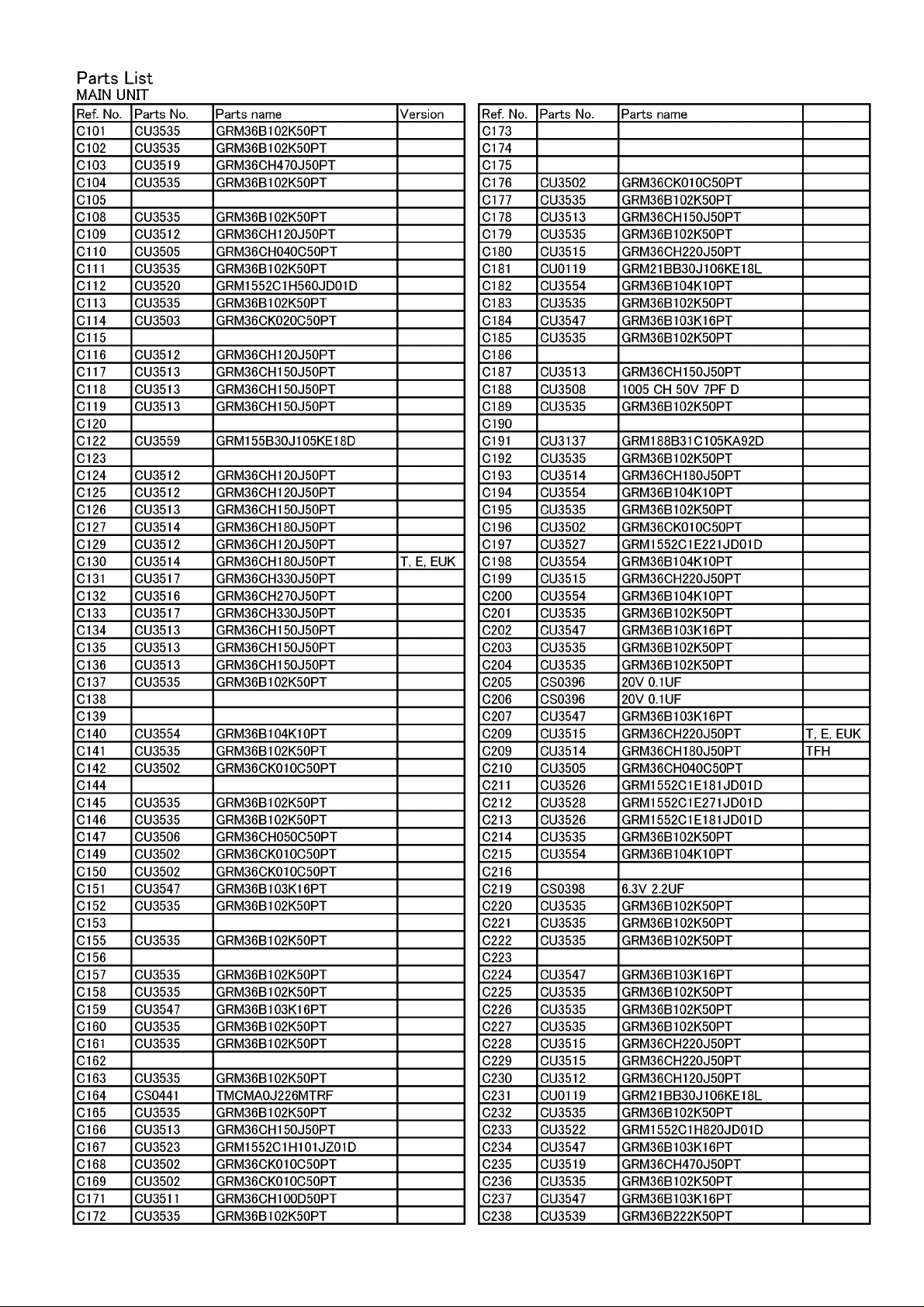
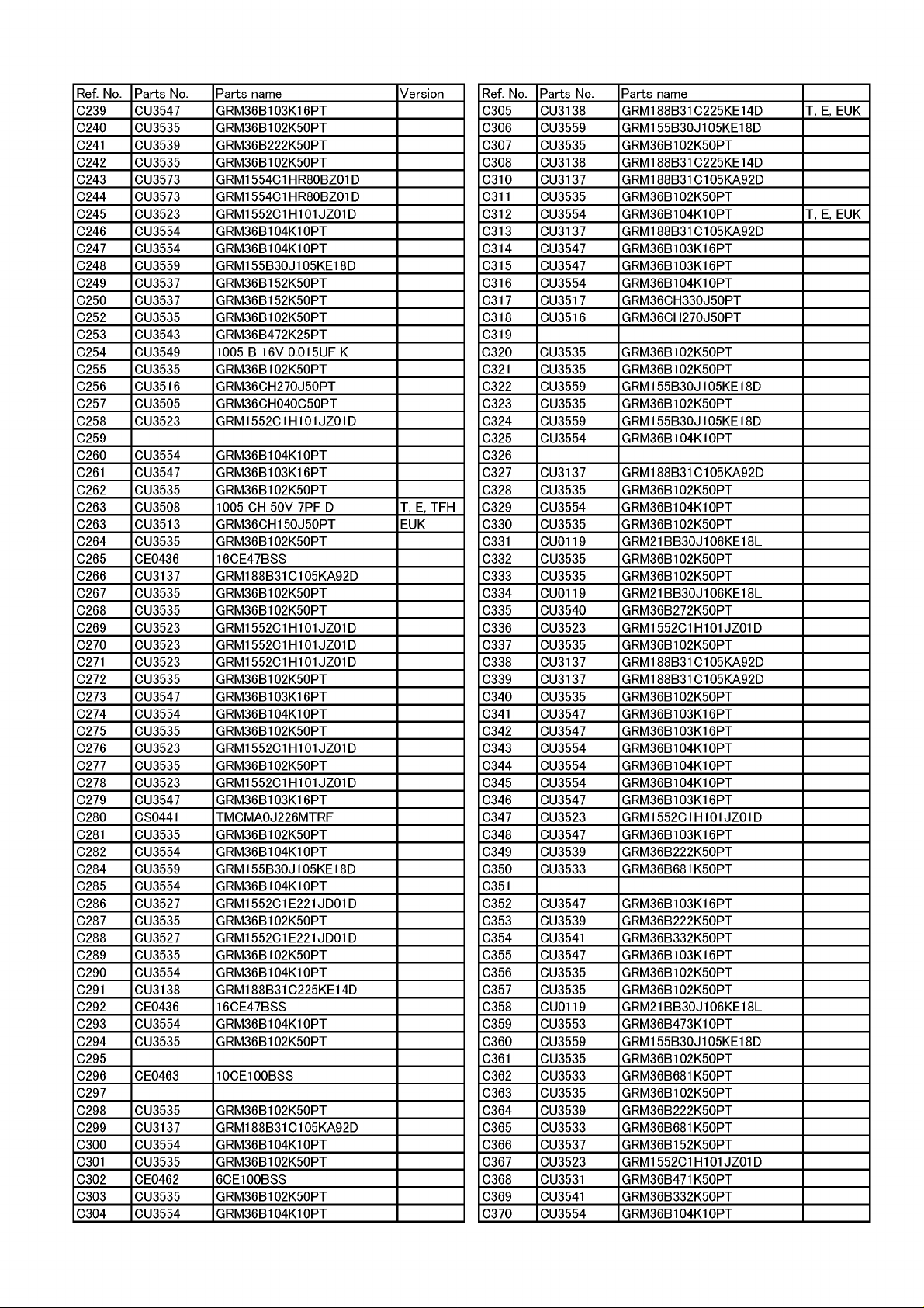
Parts List
MAIN UNIT
Ref. No. Parts No. Parts name Version
C101 CU3535 GRM36B102K50PT
C102 CU3535 GRM36B102K50PT
C103 CU3519 GRM36CH470J50PT
C104 CU3535 GRM36B102K50PT
C105
C108 CU3535 GRM36B102K50PT
C109 CU3512 GRM36CH120J50PT
C110 CU3505 GRM36CH040C50PT
C111
C112 CU3520 GRM1552C1H560JD01D
C113 CU3535 GRM36B102K50PT
C114 CU3503 GRM36CK020C50PT
C115
C116 CU3512 GRM36CH120J50PT
C117 CU3513 GRM36CH150J50PT
C118 CU3513 GRM36CH150J50PT
C119 CU3513 GRM36CH150J50PT
C120
C122 CU3559 GRM155B30J105KE18D
C123
C124 CU3512 GRM36CH120J50PT
C125 CU3512 GRM36CH120J50PT
C126 CU3513 GRM36CH150J50PT
C127 CU3514 GRM36CH180J50PT
C129 CU3512 GRM36CH120J50PT
C130 CU3514 GRM36CH180J50PT T, E, EUK
C131 CU3517 GRM36CH330J50PT
C132 CU3516 GRM36CH270J50PT
C133 CU3517 GRM36CH330J50PT
C134 CU3513 GRM36CH150J50PT
C135 CU3513 GRM36CH150J50PT
C136 CU3513 GRM36CH150J50PT
C137 CU3535 GRM36B102K50PT
C138
C139
C140 CU3554 GRM36B104K10PT
C141 CU3535 GRM36B102K50PT
C142 CU3502 GRM36CK010C50PT
C144
C145 CU3535 GRM36B102K50PT
C146 CU3535 GRM36B102K50PT
C147 CU3506 GRM36CH050C50PT
C149 CU3502 GRM36CK010C50PT
C150 CU3502 GRM36CK010C50PT
C151 CU3547 GRM36B103K16PT
C152 CU3535 GRM36B102K50PT
C153
C155 CU3535 GRM36B102K50PT
C156
C157 CU3535 GRM36B102K50PT
C158 CU3535 GRM36B102K50PT
C159 CU3547 GRM36B103K16PT
C160 CU3535 GRM36B102K50PT
C161 CU3535 GRM36B102K50PT
C162
C163 CU3535 GRM36B102K50PT
C164 CS0441 TMCMA0J226MTRF
C165 CU3535 GRM36B102K50PT
C166 CU3513 GRM36CH150J50PT
C167 CU3523 GRM1552C1H101JZ01D
C168 CU3502 GRM36CK010C50PT
C169 CU3502 GRM36CK010C50PT
C171 CU3511 GRM36CH100D50PT
C172 CU3535 GRM36B102K50PT
CU3535 GRM36B102K50PT
Ref. No. Parts No. Parts name
C173
C174
C175
C176 CU3502 GRM36CK010C50PT
C177 CU3535 GRM36B102K50PT
C178 CU3513 GRM36CH150J50PT
C179 CU3535 GRM36B102K50PT
C180 CU3515 GRM36CH220J50PT
C181 CU0119 GRM21BB30J106KE18L
C182 CU3554 GRM36B104K10PT
C183 CU3535 GRM36B102K50PT
C184 CU3547 GRM36B103K16PT
C185 CU3535 GRM36B102K50PT
C186
C187 CU3513 GRM36CH150J50PT
C188 CU3508 1005 CH 50V 7PF D
C189 CU3535 GRM36B102K50PT
C190
C191 CU3137 GRM188B31C105KA92D
C192 CU3535 GRM36B102K50PT
C193 CU3514 GRM36CH180J50PT
C194 CU3554 GRM36B104K10PT
C195 CU3535 GRM36B102K50PT
C196 CU3502 GRM36CK010C50PT
C197 CU3527 GRM1552C1E221JD01D
C198 CU3554 GRM36B104K10PT
C199 CU3515 GRM36CH220J50PT
C200 CU3554 GRM36B104K10PT
C201 CU3535 GRM36B102K50PT
C202 CU3547 GRM36B103K16PT
C203 CU3535 GRM36B102K50PT
C204 CU3535 GRM36B102K50PT
C205 CS0396 20V 0.1UF
C206 CS0396 20V 0.1UF
C207 CU3547 GRM36B103K16PT
C209 CU3515 GRM36CH220J50PT T, E, EUK
C209 CU3514 GRM36CH180J50PT TFH
C210 CU3505 GRM36CH040C50PT
C211 CU3526 GRM1552C1E181JD01D
C212 CU3528 GRM1552C1E271JD01D
C213 CU3526 GRM1552C1E181JD01D
C214 CU3535 GRM36B102K50PT
C215 CU3554 GRM36B104K10PT
C216
C219 CS0398 6.3V 2.2UF
C220 CU3535 GRM36B102K50PT
C221 CU3535 GRM36B102K50PT
C222 CU3535 GRM36B102K50PT
C223
C224 CU3547 GRM36B103K16PT
C225 CU3535 GRM36B102K50PT
C226 CU3535 GRM36B102K50PT
C227 CU3535 GRM36B102K50PT
C228 CU3515 GRM36CH220J50PT
C229 CU3515 GRM36CH220J50PT
C230 CU3512 GRM36CH120J50PT
C231 CU0119 GRM21BB30J106KE18L
C232 CU3535 GRM36B102K50PT
C233 CU3522 GRM1552C1H820JD01D
C234 CU3547 GRM36B103K16PT
C235 CU3519 GRM36CH470J50PT
C236 CU3535 GRM36B102K50PT
C237 CU3547 GRM36B103K16PT
C238 CU3539 GRM36B222K50PT
Page 9
Ref. No. Parts No. Parts name Version
C239 CU3547 GRM36B103K16PT
C240 CU3535 GRM36B102K50PT
C241 CU3539 GRM36B222K50PT
C242 CU3535 GRM36B102K50PT
C243 CU3573 GRM1554C1HR80BZ01D
C244 CU3573 GRM1554C1HR80BZ01D
C245 CU3523 GRM1552C1H101JZ01D
C246 CU3554 GRM36B104K10PT
C247 CU3554 GRM36B104K10PT
C248 CU3559 GRM155B30J105KE18D
C249 CU3537 GRM36B152K50PT
C250 CU3537 GRM36B152K50PT
C252 CU3535 GRM36B102K50PT
C253 CU3543 GRM36B472K25PT
C254 CU3549 1005 B 16V 0.015UF K
C255 CU3535 GRM36B102K50PT
C256 CU3516 GRM36CH270J50PT
C257 CU3505 GRM36CH040C50PT
C258 CU3523 GRM1552C1H101JZ01D
C259
C260 CU3554 GRM36B104K10PT
C261 CU3547 GRM36B103K16PT
C262 CU3535 GRM36B102K50PT
C263 CU3508 1005 CH 50V 7PF D T, E, TFH
C263 CU3513 GRM36CH150J50PT EUK
C264 CU3535 GRM36B102K50PT
C265 CE0436 16CE47BSS
C266 CU3137 GRM188B31C105KA92D
C267 CU3535 GRM36B102K50PT
C268 CU3535 GRM36B102K50PT
C269 CU3523 GRM1552C1H101JZ01D
C270 CU3523 GRM1552C1H101JZ01D
C271 CU3523 GRM1552C1H101JZ01D
C272 CU3535 GRM36B102K50PT
C273 CU3547 GRM36B103K16PT
C274 CU3554 GRM36B104K10PT
C275 CU3535 GRM36B102K50PT
C276 CU3523 GRM1552C1H101JZ01D
C277 CU3535 GRM36B102K50PT
C278 CU3523 GRM1552C1H101JZ01D
C279 CU3547 GRM36B103K16PT
C280 CS0441 TMCMA0J226MTRF
C281 CU3535 GRM36B102K50PT
C282 CU3554 GRM36B104K10PT
C284 CU3559 GRM155B30J105KE18D
C285 CU3554 GRM36B104K10PT
C286 CU3527 GRM1552C1E221JD01D
C287 CU3535 GRM36B102K50PT
C288 CU3527 GRM1552C1E221JD01D
C289 CU3535 GRM36B102K50PT
C290 CU3554 GRM36B104K10PT
C291 CU3138 GRM188B31C225KE14D
C292 CE0436 16CE47BSS
C293 CU3554 GRM36B104K10PT
C294 CU3535 GRM36B102K50PT
C295
C296 CE0463 10CE100BSS
C297
C298 CU3535 GRM36B102K50PT
C299 CU3137 GRM188B31C105KA92D
C300 CU3554 GRM36B104K10PT
C301 CU3535 GRM36B102K50PT
C302 CE0462 6CE100BSS
C303 CU3535 GRM36B102K50PT
C304 CU3554 GRM36B104K10PT
Ref. No. Parts No. Parts name
C305 CU3138 GRM188B31C225KE14D T, E, EUK
C306 CU3559 GRM155B30J105KE18D
C307 CU3535 GRM36B102K50PT
C308 CU3138 GRM188B31C225KE14D
C310 CU3137 GRM188B31C105KA92D
C311 CU3535 GRM36B102K50PT
C312 CU3554 GRM36B104K10PT T, E, EUK
C313 CU3137 GRM188B31C105KA92D
C314 CU3547 GRM36B103K16PT
C315 CU3547 GRM36B103K16PT
C316 CU3554 GRM36B104K10PT
C317 CU3517 GRM36CH330J50PT
C318 CU3516 GRM36CH270J50PT
C319
C320 CU3535 GRM36B102K50PT
C321 CU3535 GRM36B102K50PT
C322 CU3559 GRM155B30J105KE18D
C323 CU3535 GRM36B102K50PT
C324 CU3559 GRM155B30J105KE18D
C325 CU3554 GRM36B104K10PT
C326
C327 CU3137 GRM188B31C105KA92D
C328 CU3535 GRM36B102K50PT
C329 CU3554 GRM36B104K10PT
C330 CU3535 GRM36B102K50PT
C331 CU0119 GRM21BB30J106KE18L
C332 CU3535 GRM36B102K50PT
C333 CU3535 GRM36B102K50PT
C334 CU0119 GRM21BB30J106KE18L
C335 CU3540 GRM36B272K50PT
C336 CU3523 GRM1552C1H101JZ01D
C337 CU3535 GRM36B102K50PT
C338 CU3137 GRM188B31C105KA92D
C339 CU3137 GRM188B31C105KA92D
C340 CU3535 GRM36B102K50PT
C341 CU3547 GRM36B103K16PT
C342 CU3547 GRM36B103K16PT
C343 CU3554 GRM36B104K10PT
C344 CU3554 GRM36B104K10PT
C345 CU3554 GRM36B104K10PT
C346 CU3547 GRM36B103K16PT
C347 CU3523 GRM1552C1H101JZ01D
C348 CU3547 GRM36B103K16PT
C349 CU3539 GRM36B222K50PT
C350 CU3533 GRM36B681K50PT
C351
C352 CU3547 GRM36B103K16PT
C353 CU3539 GRM36B222K50PT
C354 CU3541 GRM36B332K50PT
C355 CU3547 GRM36B103K16PT
C356 CU3535 GRM36B102K50PT
C357 CU3535 GRM36B102K50PT
C358 CU0119 GRM21BB30J106KE18L
C359 CU3553 GRM36B473K10PT
C360 CU3559 GRM155B30J105KE18D
C361 CU3535 GRM36B102K50PT
C362 CU3533 GRM36B681K50PT
C363 CU3535 GRM36B102K50PT
C364 CU3539 GRM36B222K50PT
C365 CU3533 GRM36B681K50PT
C366 CU3537 GRM36B152K50PT
C367 CU3523 GRM1552C1H101JZ01D
C368 CU3531 GRM36B471K50PT
C369 CU3541 GRM36B332K50PT
C370 CU3554 GRM36B104K10PT
Page 10

Ref. No. Parts No. Parts name Version
C371 CU3535 GRM36B102K50PT
C372 CU3559 GRM155B30J105KE18D
C373
C375 CU3541 GRM36B332K50PT
C376 CU3554 GRM36B104K10PT
C377 CU3554 GRM36B104K10PT
C378
C379 CU3535 GRM36B102K50PT
C380 CU3535 GRM36B102K50PT
C381 CU3535 GRM36B102K50PT
C382 CS0439 TMCMA0J476MF
C383 CU3535 GRM36B102K50PT
C384 CU3535 GRM36B102K50PT
C385 CU3535 GRM36B102K50PT
C386 CU0119 GRM21BB30J106KE18L
C387 CU3535 GRM36B102K50PT
C388 CU3535 GRM36B102K50PT
C389 CU3535 GRM36B102K50PT
C390 CU3554 GRM36B104K10PT
C391 CU3535 GRM36B102K50PT
C392 CU3535 GRM36B102K50PT
C393 CU0119 GRM21BB30J106KE18L
C394 CU3512 GRM36CH120J50PT
C395 CU3535 GRM36B102K50PT
C396 CU3535 GRM36B102K50PT
C397 CU3535 GRM36B102K50PT
C398 CU3138 GRM188B31C225KE14D
C399
C400
C401 CU3554 GRM36B104K10PT
C403 CS0441 TMCMA0J226MTRF
C404 CU3554 GRM36B104K10PT
C413 CU3559 GRM155B30J105KE18D T, E, EUK
C414 CU3554 GRM36B104K10PT
C415 CU3554 GRM36B104K10PT
CN101
CN102
D101 XD0422 HSC277TRF-E
D103 XD0419 1SS400TE61
D104
D105 XD0421 1SV323(TPH3,H)
D106 XD0422 HSC277TRF-E
D107 XD0421 1SV323(TPH3,H)
D108 XD0453 RB717F
D109
D110 XD0451 015AZ3.0-X(TPL3,F)
D111
D112 XD0422 HSC277TRF-E
D113 XD0422 HSC277TRF-E
D114 XD0421 1SV323(TPH3,H)
D115 XD0421 1SV323(TPH3,H)
D116
D117 XD0421 1SV323(TPH3,H)
D118 XD0421 1SV323(TPH3,H)
D119 XD0421 1SV323(TPH3,H)
D120 XD0421 1SV323(TPH3,H)
D121 XL0097 SML-521MUWT86
D122 XD0338 1SS362(TE85L)
D123 XL0036 LED SML-310MT
D124 XL0036 LED SML-310MT
D125 XL0036 LED SML-310MT
D126 XL0036 LED SML-310MT
D127 XD0418 RB521S-30TE61
D128 XL0036 LED SML-310MT
D129 XL0036 LED SML-310MT
Ref. No. Parts No. Parts name
D130 XD0418 RB521S-30TE61
FL101 XF0059 Q21707AD27-21.7MHZ EUK
FL101 XF0051 Q2175AD20 21.7MHZ T, E, TFH
FL102 XF0059 Q21707AD27-21.7MHZ EUK
FL102 XF0051 Q2175AD20 21.7MHZ T, E, TFH
FL103 XC0052 ALFYM450G=K EUK
FL103 XC0060 ALFYM450F=K T, E, TFH
IC101 XA1103 LM2904PWR
IC102 XA1107 MB15E07SRPFTGBNDEFE1
IC103 XA0404 TA31136FNG(EL)
IC104 XA0210 IC NJM2070M
IC105 XA1293 M62364FP#DF1G
IC106 XA1119 XC6202P502MR
IC107 XA0617 TC75S56FU(TE85) T, E, EUK
IC108 XA1120 S80845CLNB-B66-T2G
IC109 XA1117 S24CS64A01-J8T1G
IC110 XA1106 LM2902PWR
IC111 XA1106 LM2902PWR
IC112 XA1106 LM2902PWR
IC113 XA1358 UPD78F0395GC-8EA-A T, E, EUK
IC113 XA1292 UPD78F0394GC-8EA-A TFH
JK101 UJ0019 HSJ1493-01-010
JK102 UJ0022 HSJ1102-01-540
L101 QS401556 0.40-1.55-6TL
L102 QS402006 0.40-2.0-6TL
L104 QS402006 0.40-2.0-6TL
L105 QS401405 0.40-1.4-5TL
L106 QS501403 0.50-1.4-3TL
L108 QC0812 1005 100NH
L109
L110 QC0757 C1608CB22NJ
L111
L112 QS402057 0.40-2.05-7TL
L113 QC0875 C2012H68NH
L114 QC0902 C2012C1R0J
L115 QC0812 1005 100NH
L116 QC0736 LK10052R2K-B
L117 QB0057 MPZ1608S101AT
L118 QS402057 0.40-2.05-7TL
L120 QB0057 MPZ1608S101AT
L121 QC0818 C2012H82NH
L123 QC0736 LK10052R2K-B
L124 QC0773 C1608CBR47J
L125 QC0773 C1608CBR47J
L126 QC0769 1608CBR22J
L127 QC0765 1608 100NH
L128
L129 QC0812 1005 100NH
L130
L132 QC0842 LB2518T221K
L133 QC0812 1005 100NH
L134 QC0902 C2012C1R0J
L135 QC0875 C2012H68NH
L136 QC0875 C2012H68NH
L137 QC0875 C2012H68NH
L138 QC0875 C2012H68NH
L139 QC0874 C2012H56NH
L140
L141 QC0935 LB2012T150K
L142 QB0057 MPZ1608S101AT
L143
LCD101 EL0059 LCD DJ170
MIC101 EY0017 OB-27P44
Q101 XT0180 2SC5066FT-Y(TE85L)
Q102 XE0090 SSM3J15FV(TPL3,Z)
Page 11

Ref. No. Parts No. Parts name Version
Q104 XT0210 2SC6026MFV-GR
Q105 XE0091 RQA0002DNS
Q106 XE0092 RQA0004PXDQS
Q107
Q108 XT0219 15GN03F-TL-E
Q110 XU0211 RN2107FV
Q111 XU0210 RN1107FV
Q112 XT0219 15GN03F-TL-E
Q113 XT0219 15GN03F-TL-E
Q114 XT0213 2SC5659T2L
Q115 XT0219 15GN03F-TL-E
Q116 XT0219 15GN03F-TL-E
Q117 XT0214 HN2C01FE-GR(T5L,F)
Q118 XE0053 3SK293TE85L
Q119 XE0053 3SK293TE85L
Q120 XT0210 2SC6026MFV-GR
Q121 XT0213 2SC5659T2L
Q122
Q123 XU0220 RN2111MFV(TPL3)
Q124 XT0223 2SA2070(TE12L,F)
Q125 XU0211 RN2107FV T, E, EUK
Q126
Q127 XU0220 RN2111MFV(TPL3)
Q128 XT0214 HN2C01FE-GR(T5L,F)
Q129 XU0210 RN1107FV
Q130 XU0212 RN2115FV
Q131 XU0210 RN1107FV
Q132 XT0210 2SC6026MFV-GR
Q133 XU0213 RN1111FV TPL3
Q134 XT0223 2SA2070(TE12L,F)
Q135 XT0212 2SA1955FV-A(TPL3)
Q136 XT0212 2SA1955FV-A(TPL3)
Q137 XT0212 2SA1955FV-A(TPL3)
Q138 XU0213 RN1111FV TPL3
Q139 XT0214 HN2C01FE-GR(T5L,F)
Q140 XU0213 RN1111FV TPL3
Q142 XE0090 SSM3J15FV(TPL3,Z)
R101 RK3562 1005 1/16W 100K OHMJ
R104 RK3526 1005 1/16W 100 OHM J
R105 RK3566 1005 1/16W 220K OHMJ
R106 RK3501 1005 1/16W 0 OHM J
R107 RK3534 1005 1/16W 470 OHM J
R108 RK3550 1005 1/16W 10K OHM J
R111
R112 RK3530 1005 1/16W 220 OHM J
R113 RK3546 1005 1/16W 4.7K OHMJ
R114 RK3538 1005 1/16W 1.0K OHMJ
R116 RK3526 1005 1/16W 100 OHM J
R117 RK3014 1608 1/10W 10 OHM J
R118 RK3518 1005 1/16W 22 OHM J
R119 RK3562 1005 1/16W 100K OHMJ
R120 RK3530 1005 1/16W 220 OHM J
R121
R122 RK3542 1005 1/16W 2.2K OHMJ
R123
R124 RK3552 1005 1/16W 15K OHM J
R126
R127 RK3557 1005 1/16W 39K OHM J
R128 RK3562 1005 1/16W 100K OHMJ
R130 RK3562 1005 1/16W 100K OHMJ
R131
R132 RK3557 1005 1/16W 39K OHM J
R133 RK3518 1005 1/16W 22 OHM J
R134 RK3501 1005 1/16W 0 OHM J
R135 RK3551 1005 1/16W 12K OHM J
RK3550 1005 1/16W 10K OHM J
RK3558 1005 1/16W 47K OHM J
Ref. No. Parts No. Parts name
R136 RK3562 1005 1/16W 100K OHMJ
R137 RK3551 1005 1/16W 12K OHM J
R138
R141
R142 RK3530 1005 1/16W 220 OHM J
R143 RK3550 1005 1/16W 10K OHM J
R144 RK3526 1005 1/16W 100 OHM J
R145 RK3532 1005 1/16W 330 OHM J
R146 RK3550 1005 1/16W 10K OHM J
R147 RK3501 1005 1/16W 0 OHM J
R148
R149 RK3552 1005 1/16W 15K OHM J
R150 RK3554 1005 1/16W 22K OHM J
R151 RK3537 1005 1/16W 820 OHM J
R152
R153 RK3550 1005 1/16W 10K OHM J
R154 RK3570 1005 1/16W 470K OHMJ
R155 RK3552 1005 1/16W 15K OHM J
R156 RK3562 1005 1/16W 100K OHMJ
R157 RK3546 1005 1/16W 4.7K OHMJ
R158 RK3570 1005 1/16W 470K OHMJ
R159 RK3538 1005 1/16W 1.0K OHMJ
R160
R162 RK3538 1005 1/16W 1.0K OHMJ
R163 RK3542 1005 1/16W 2.2K OHMJ
R164 RK3550 1005 1/16W 10K OHM J
R165 RK3501 1005 1/16W 0 OHM J
R166 RK3537 1005 1/16W 820 OHM J
R167 RK3539 1005 1/16W 1.2K OHMJ
R168 RK3558 1005 1/16W 47K OHM J
R169
R170 RK3530 1005 1/16W 220 OHM J
R171 RK3564 1005 1/16W 150K OHMJ
R172 RK3570 1005 1/16W 470K OHMJ
R173 RK3550 1005 1/16W 10K OHM J
R174 RK3526 1005 1/16W 100 OHM J
R175
R176 RK3530 1005 1/16W 220 OHM J
R177 RK3530 1005 1/16W 220 OHM J
R178 RK3570 1005 1/16W 470K OHMJ
R179 RK3550 1005 1/16W 10K OHM J
R180 RK3538 1005 1/16W 1.0K OHMJ
R181 RK3518 1005 1/16W 22 OHM J
R183 RK3538 1005 1/16W 1.0K OHMJ
R184 RK3550 1005 1/16W 10K OHM J
R185 RK3574 1005 1/16W 1.0M OHMJ
R186 RK3538 1005 1/16W 1.0K OHMJ
R187 RK3542 1005 1/16W 2.2K OHMJ
R188 RK3522 1005 1/16W 47 OHM J
R189 RK3550 1005 1/16W 10K OHM J
R190 RK3556 1005 1/16W 33K OHM J
R191 RK3562 1005 1/16W 100K OHMJ
R192 RK3574 1005 1/16W 1.0M OHMJ
R193 RK3562 1005 1/16W 100K OHMJ
R194 RK3562 1005 1/16W 100K OHMJ
R195 RK3560 1005 1/16W 6 8 K OHM J
R196 RK3566 1005 1/16W 220K OHMJ
R198 RK3550 1005 1/16W 10K OHM J
R199 RK3570 1005 1/16W 470K OHMJ
R200 RK3550 1005 1/16W 10K OHM J
R201 RK3550 1005 1/16W 10K OHM J
R202 RK3558 1005 1/16W 47K OHM J
R203 RK3562 1005 1/16W 100K OHMJ
R204 RK3570 1005 1/16W 470K OHMJ
R205 RK3542 1005 1/16W 2.2K OHMJ
Page 12

Ref. No. Parts No. Parts name Version
R206 RK3536 1005 1/16W 680 OHM J EUK
R206 RK3539 1005 1/16W 1.2K OHMJ T, E, TFH
R207 RK3536 1005 1/16W 680 OHM J EUK
R207 RK3539 1005 1/16W 1.2K OHMJ T, E, TFH
R208 RK3550 1005 1/16W 10K OHM J
R209 RK3556 1005 1/16W 33K OHM J
R210 RK3538 1005 1/16W 1.0K OHMJ
R211 RK3550 1005 1/16W 10K OHM J
R212 RK3518 1005 1/16W 22 OHM J
R213 RK3550 1005 1/16W 10K OHM J
R214 RK3518 1005 1/16W 22 OHM J
R215 RK3574 1005 1/16W 1.0M OHMJ
R216 RK3574 1005 1/16W 1.0M OHMJ
R217 RK3574 1005 1/16W 1.0M OHMJ
R218
R219 RK3550 1005 1/16W 10K OHM J
R220 RK3574 1005 1/16W 1.0M OHMJ
R221 RK3574 1005 1/16W 1.0M OHMJ
R222 RK3564 1005 1/16W 150K OHMJ
R223
R225 RK3550 1005 1/16W 10K OHM J T, E, TFH
R225 RK3547 1005 1/16W 5.6K OHMJ EUK
R226 RK3550 1005 1/16W 10K OHM J
R227 RK3564 1005 1/16W 150K OHMJ
R228 RK3554 1005 1/16W 22K OHM J
R229 RK3544 1005 1/16W 3.3K OHMJ
R230 RK3501 1005 1/16W 0 OHM J
R231 RK3514 1005 1/16W 10 OHM J
R233 RK3536 1005 1/16W 680 OHM J
R234 RK3532 1005 1/16W 330 OHM J
R235 RK3562 1005 1/16W 100K OHMJ
R237 RK3570 1005 1/16W 470K OHMJ
R239 RK3574 1005 1/16W 1.0M OHMJ
R240 RK3562 1005 1/16W 100K OHMJ T, E, EUK
R241 RK3550 1005 1/16W 10K OHM J T, E, EUK
R242 RK3566 1005 1/16W 220K OHMJ
R243 RK3566 1005 1/16W 220K OHMJ
R244 RK3550 1005 1/16W 10K OHM J T, E, EUK
R245 RK3553 1005 1/16W 18K OHM J
R246 RK3550 1005 1/16W 10K OHM J
R247 RK3574 1005 1/16W 1.0M OHMJ
R248 RK3550 1005 1/16W 10K OHM J
R249 RK3550 1005 1/16W 10K OHM J
R250 RK3550 1005 1/16W 10K OHM J
R251 RK3546 1005 1/16W 4.7K OHMJ
R252 RK3526 1005 1/16W 100 OHM J T, E, EUK
R253 RK3550 1005 1/16W 10K OHM J T, E, EUK
R254 RK3553 1005 1/16W 18K OHM J
R255 RK3566 1005 1/16W 220K OHMJ
R256 RK3562 1005 1/16W 100K OHMJ
R257 RK1018 3216 1/8 W 100 OHM J
R258 RK3566 1005 1/16W 220K OHMJ
R259 RK3501 1005 1/16W 0 OHM J T, E, EUK
R260 RK3562 1005 1/16W 100K OHMJ T, E, EUK
R261
R262 RK3542 1005 1/16W 2.2K OHMJ
R263 RK3554 1005 1/16W 22K OHM J
R265 RK3550 1005 1/16W 10K OHM J
R266 RK3574 1005 1/16W 1.0M OHMJ
R267 RK3538 1005 1/16W 1.0K OHMJ
R268 RK3562 1005 1/16W 100K OHMJ
R269 RK3558 1005 1/16W 47K OHM J
R270 RK3550 1005 1/16W 10K OHM J
R271 RK3538 1005 1/16W 1.0K OHMJ
R273 RK3560 1005 1/16W 6 8 K OHM J
Ref. No. Parts No. Parts name
R276 RK3552 1005 1/16W 15K OHM J
R277 RK3552 1005 1/16W 15K OHM J
R278 RK3550 1005 1/16W 10K OHM J
R279 RK3514 1005 1/16W 10 OHM J
R280 RK3562 1005 1/16W 100K OHMJ
R281 RK3562 1005 1/16W 100K OHMJ
R282 RK3538 1005 1/16W 1.0K OHMJ
R283 RK3550 1005 1/16W 10K OHM J
R284 RK3550 1005 1/16W 10K OHM J
R285 RK3562 1005 1/16W 100K OHMJ
R286 RK3562 1005 1/16W 100K OHMJ
R287 RK3550 1005 1/16W 10K OHM J
R288 RK3560 1005 1/16W 6 8 K OHM J
R289 RK3558 1005 1/16W 47K OHM J
R290 RK3566 1005 1/16W 220K OHMJ
R291 RK3558 1005 1/16W 47K OHM J
R292 RK3562 1005 1/16W 100K OHMJ
R293 RK3562 1005 1/16W 100K OHMJ
R294 RK3562 1005 1/16W 100K OHMJ
R295 RK3562 1005 1/16W 100K OHMJ
R297 RK3550 1005 1/16W 10K OHM J
R298 RK3554 1005 1/16W 22K OHM J
R299 RK3554 1005 1/16W 22K OHM J
R300 RK3556 1005 1/16W 33K OHM J
R301 RK3550 1005 1/16W 10K OHM J
R302 RK3554 1005 1/16W 22K OHM J
R303 RK3559 1005 1/16W 56K OHM J
R304 RK3550 1005 1/16W 10K OHM J
R305 RK3568 1005 1/16W 330K OHMJ
R306 RK3536 1005 1/16W 680 OHM J
R307 RK3562 1005 1/16W 100K OHMJ
R308 RK3550 1005 1/16W 10K OHM J
R309 RK3550 1005 1/16W 10K OHM J
R310 RK3546 1005 1/16W 4.7K OHMJ
R311 RK3550 1005 1/16W 10K OHM J
R312 RK3550 1005 1/16W 10K OHM J
R313 RK3559 1005 1/16W 56K OHM J
R314 RK3559 1005 1/16W 56K OHM J
R316 RK3550 1005 1/16W 10K OHM J
R317 RK3570 1005 1/16W 470K OHMJ
R318 RK3546 1005 1/16W 4.7K OHMJ
R319 RK3559 1005 1/16W 56K OHM J
R320 RK3562 1005 1/16W 100K OHMJ
R321
R324 RK3558 1005 1/16W 47K OHM J
R325 RK3558 1005 1/16W 47K OHM J
R326 RK3562 1005 1/16W 100K OHMJ
R327 RK3566 1005 1/16W 220K OHMJ
R328 RK3559 1005 1/16W 56K OHM J
R329 RK3556 1005 1/16W 33K OHM J TFH
R329 RK3557 1005 1/16W 39K OHM J T, E, EUK
R330 RK3550 1005 1/16W 10K OHM J TFH
R330 RK3551 1005 1/16W 12K OHM J T, E, EUK
R331 RK3550 1005 1/16W 10K OHM J
R333 RK3546 1005 1/16W 4.7K OHMJ
R334 RK3546 1005 1/16W 4.7K OHMJ
R335 RK3546 1005 1/16W 4.7K OHMJ
R336 RK3546 1005 1/16W 4.7K OHMJ
R337 RK3558 1005 1/16W 47K OHM J
R338 RK3558 1005 1/16W 47K OHM J
R339
R340 RK3552 1005 1/16W 15K OHM J
R341 RK3562 1005 1/16W 100K OHMJ
R342 RK3537 1005 1/16W 820 OHM J
R343 RK3550 1005 1/16W 10K OHM J
Page 13

Ref. No. Parts No. Parts name Version
R344 RK3537 1005 1/16W 820 OHM J
R345 RK3546 1005 1/16W 4.7K OHMJ
R346 RK3562 1005 1/16W 100K OHMJ
R347 RK3562 1005 1/16W 100K OHMJ
R348 RK3562 1005 1/16W 100K OHMJ
R349 RK3550 1005 1/16W 10K OHM J
R350 RK3550 1005 1/16W 10K OHM J
R351 RK3542 1005 1/16W 2.2K OHMJ
R352 RK3550 1005 1/16W 10K OHM J
R353 RK3538 1005 1/16W 1.0K OHMJ
R354 RK3550 1005 1/16W 10K OHM J
R355 RK3538 1005 1/16W 1.0K OHMJ
R356 RK3536 1005 1/16W 680 OHM J
R357 RK3550 1005 1/16W 10K OHM J
R358 RK3538 1005 1/16W 1.0K OHMJ
R359 RK3566 1005 1/16W 220K OHMJ
R360 RK3562 1005 1/16W 100K OHMJ
R361 RK3554 1005 1/16W 22K OHM J
R362
R363
R363 RK3538 1005 1/16W 1.0K OHMJ TFH
R363 RK3564 1005 1/16W 150K OHMJ E, EUK
R365 RK3534 1005 1/16W 470 OHM J
R366 RK3501 1005 1/16W 0 OHM J
R367 RK3501 1005 1/16W 0 OHM J
R368 RK3546 1005 1/16W 4.7K OHMJ
R369 RK3538 1005 1/16W 1.0K OHMJ
R370 RK3550 1005 1/16W 10K OHM J
R371 RK3562 1005 1/16W 100K OHMJ
R372 RK3560 1005 1/16W
R372 RK3554 1005 1/16W 22K OHM J TFH
R373 RK3574 1005 1/16W 1.0M OHMJ
R374 RK3558 1005 1/16W 47K OHM J
R375 RK3562 1005 1/16W 100K OHMJ
R376
R377 RK3558 1005 1/16W 47K OHM J
R378 RK3558 1005 1/16W 47K OHM J
SW101 UU0043 EVQPJ705K
TH101
W101 MRCL07AA #30R02-070-02
W102 MACL07AA #30A02-070-02
W103 MACLH2GG #30AH1-025-H1 T, E
X102 XQ0208 DSX321SC21.250MHZ
X103 XK0005 CDBCB450KCAY24-R0
X104 XQ0212 SMD-49 8.192MHZ
UP0619A DJ175INTEGRATED-A
AF0003 0PH M2+3 FE/N3
AF0030 0PH2+6FE/N1
AN0034 M6 NUT BR/B.N
AN0042 DIAL NUT
AX0009 OPH P2+6 FE/N 1
DG0046 LCD LIGHT DJ170
DP0195 LCD PANEL
ES0027 36-8BB-10B2 ROHS
FG0234Y MIC HOLDER DJ190
FG0392 WATERPROOF CAP
FG0418 LCD RUB CONE
FG0478 KEYBOAD
FG0479 PTT RUBBER
FG0480 JACK CAP
FM0265A HEAT SINK, DJV17
FM0300 ANT GND DJ175
FP0310 TERMINAL CASE
FP0321 SPACER
FP0324 BLIND SHEET DJ175
6 8K OHM J T, E, EUK
Ref. No. Parts No. Parts name
KZ0219 FRONT CASE ASSYDJ175
NK0081 KNOB
SD0111A BATTERY TERMINAL
SD0137 TERMINAL
SP0013 KNOB SPRING 7800
SS0112 CHASSIS
ST0089 LCD HOLDER
TL0033 REFLECTIVE SHEET
TS0188 VCO CASE DJ175
UE0571 SMA ANT CONNECTOR
UR0027 ROTARY ENCODER
YX0045 LCD TAPE
CHARGER UNIT (EDC-165)
Ref. No. Parts No. Parts name
D101 XL0125 MVR3338S
JK101 UJ0033 HEC2781-010520
R101 RF0027 SPR3 56 OHM
R102 RK3038 1608 1/10W 1.0KOHM J
R103
UP0613 EDC165 INTEGRATED
AP0017 PH P2.6+10 FE/B.ZN
DD0017 BLIND SHEET
KS0103 BOTTOM CASE EDC165
KU0162 UPPER CASE EDC164
SP0020 CHARGE TERMINAL
TT1002 1.0X1MM
ACCESSORIES
BB0009Y HAND STRAP DJS41
BH0011 BELT CLIP
DS0446 NITTO MODEL PLATE(S)
EA0141 ANTENNA EA0141 T, E, EUK
EA0142 ANTENNA EA0142 TFH
EDC146 AC ADAPTOR 120 V T
EDC147 AC ADAPTOR 230V T, E, EUK
EDC148 AC ADAPTOR 230V UK PLUG EUK
EBP072 NI-MH BATTERY PACK
Page 14

EXPLODED VIEW
DP0195
KZ0219
FG0392
NK0081
FG0480 FG0479 ES0027
Page 15

ST0089
Page 16

PC Board View
MAIN - Side A
Page 17

PC Board View
MAIN - Side B
Page 18

PC Board View EDC165
Side-A
T103 T101 T102
o o
O o
o
O
o
o
Side-B
C D C D
o o
R102
n
R103
o
Page 19

Adjustments:
1) Required Test Equipment
The following items are required to adjust radio parameters
1.Regulated power supply
2.Digital multim eter
3.Oscilloscope
4.Audio dummy load
5.SSG
6.Power meter
Supply voltage:
Current:
Voltage range:
Current:
Input resistance:
Measurable frequency: Audio frequency
Impedance:
Dissipation:
Jack:
Output frequency:
Impedance:
Modulation:
7 - 8 DC
3A or more
FS = Approx. 20V
10A or more
High impedance
8Q
1W or more
3.5mmO
200MHz or more
50 Q, unbalanced
FM
7.Audio volmeter
.Audio generator
9.Distortion meter/SINAD meter
10.Frequency counter
Measurable frequency:
Impedance:
Measuring range:
Measurable frequency:
Sensitivity:
Output frequency:
Output impedance:
Measurable frequency:
Input level:
Distortion:
Measurable frequency:
Measurable stability:
Up to 200MHz
50 Q, unbalanced
0.1W-10W
Up to 100kHz
1mV to 10V
67Hz to 10kHz
600 Q, unbalanced
1kHz
Up to 40dB
1%-100%
Up to 200MHz
Approx. ±0.1ppm
Page 20

11.Linear detector
12. DC Ammeter
Measurable frequency: Up to 200MHz
Characteristics: Flat
CN: 60dB or more
Current: 3A or more
Note:
(1). SSG initial setting
Modulation Frequency:1kHz
Modulation Level:3.0kHz (T, E, TFH)/ 1.5kHz (EUK)
(2). Reference sensitivity: 12dB SINAD
(3). Specified audio output level: 500mW at 8Q
(4). Standard audio output level: 50mW at 8Q
(5). Use an RF cable ( 3D2W:1M ) for test equipment.
(6). Attach a fuse to the RF test equipment.
(7). All SSG outputs are indicated by EMF
(8). Supply voltage for the transceiver: 7.2VDC
Page 21

2) Adjustment mode
The adjustm ent should be operated in the Adjustment mode. Therefore except for the reference
frequency, deviation and tone-deviation adjustments an operator won’t touch the components on
the board, but most of the adjustments should be done by operating the dial and keys on the unit.
During such operation, memory channels are used temporary therefore it is required to program
memories before the unit is set to the adjustm ent mod. Please refer the chart below for the
programming channels. The frequencies may be varied within the range of ±0.2M hz depending
on the RF environm ent around your work area, and refer the instruction m anual for how to
program the memories into the memory-channels.
To enter the adjustm ent mode, press “F” then “KL” to key-lock the unit. Then press the
numeric keys in order of ”4”, “9”, “0”, “2”, “1” and “7”. Observe th at decimal points appear on the
display below 100MHz and 10MHz digits. To exit from the adjustm ent mode, repeat the whole
sequence (key-lock then enter the code in order). NEVER RESET THE UNIT WHILE
OPERATING IN THE SET MODE. This may reset whole adjustm ent values resulting the
malfunction of the unit in the operating mode. The chart below shows the adjustm ent points and
interface between the unit and instrum ents. Please use an attenuator in case the specifications of
the linear-detector and frequency counter may exceed the requirem ent herein.
* Simply memory the frequencies only into the relative memory channels.
Channe
l
1 Frequnecy Adjustment 145.000
2 TX-output / High power 145.000
3 TX-output / Mid power 145.000
4 TX-output / Low power 145.000
5 Microphone deviation 145.000
6 CTCSS tone deviation 145.000
7 DCS deviation 145.000
11 Sensitivity adjustment (lower edge) 137.000
12 Sensitivity adjustment (center range) 150.000
13 Sensitivity adjustment (upper range) 173.000
14 Squelch adjustment (minimum) 145.000
15 Squelch adjustment (maximum) 145.000
16 S-meter adjustment (1) 145.000
17 S-meter adjustment (Full) 145.000
Adjustment menu
Frequency
T, E, EUK TFH
162.000
162.000
162.000
162.000
162.000
162.000
162.000
137.000
150.000
173.000
162.000
162.000
162.000
162.000
Page 22

1. Frequency adjustm ent
Select memory ch.1.
Press PTT on the unit to transmit and m easure the TX frequency. One of digits 00-FF
should appear on the display where memory channel number was shown. Rotate the dial
on the unit to adjust the frequency to bring the value to the range specified below.
Specification value : ± 50Hz
Necessary instrum ent: (1). Frequency counter
2. TX output - High power
Select memory ch.2.
Press PTT on the unit to transm it. One of digits 00-FF should appear on the display
where memory channel num ber was shown. Rotate the dial on the unit to adjust the TX
power to meet the specification. Release the PTT to finish the adjustment. Be sure to
check the consuming current value after the adjustm ent is completed.
Specification:
TX-output power/High: 5.0 watts
Current consumption / 1.6A or less
Necessary instrum ent: (1). DC Ammeter
(2). Power meter
3. TX output - Middle power
Select memory ch.3.
Press PTT on the unit to transmit. One of digits 00-FF should appear on the display
where memory channel num ber was shown. Rotate the dial on the unit to adjust the TX
power to m eet the specification. Release the PTT to finish the adjustment.
Specification: 2.0 watts
Necessary instrum ent: (1). Power meter
4. TX output - Low power
Select memory ch.4.
Press PTT on the unit to transm it. One of digits 0-F should appear on the display where
memory channel number was shown. Rotate the dial on the unit to adjust the TX power
to meet the specification. Release the PTT to finish the adjustment.
Specification: 0.5 watts
Necessary instrument: (1). Power meter
Page 23

5. Microphone deviation
Select memory ch.5.
Input the signal as specified below from an Audio generator and transm it. Measure the
deviation value using a Liner-detector. Press PTT on the unit to transmit. One of digits
00-FF should appear on the display where memory channel number was shown. Rotate
the dial on the unit to adjust the deviation to meet the specification. Release the PTT to
finish the adjustment.
Specification : 4.3±0.1kHz (T, E, TFH)
2.2 ± 0.1kHz (EUK)
Measuring condition:(1). Audio generator setting
Frequency: 1kHz
Output Level:50mV
Necessary instrument:(1). Audio generator
(2). Linear detector
6. CTCSS tone 88.5Hz deviation and adjustm ent of the sign-wave
Select memory ch.6.
Press PTT to automatically transm it 88.5Hz tone. Measure the deviation value using a
Liner-detector. Press PTT on the unit to transm it. One of digits 00-FF should appear on
the display where memory channel num ber was shown. Rotate the dial on the unit to
adjust the tone deviation to meet the specification below. Use an oscilloscope to monitor
the sign-wave then correct the wave shape (see the chart 1 below).
Specification: 0.80±0.05KHz (T, E)
OK
0.90±0.05KHz (TFH)
0.50±0.05KHz (EUK)
NG
Necessary instrument:(1). Linear detector
(2). Oscilloscope
Chart 1: sign-wave correction
7. DCS 255 deviation
Select memory ch.7.
Press PTT to autom atically transm it DCS code of 255. Measure the deviation value using
NG
a Liner-detector. Press PTT on the unit to transmit. One of digits 00-FF should appear on
the display where memory channel num ber was shown. Rotate the dial on the unit to
adjust the tone deviation to meet the specification below.
Specification: 0.80±0.05KHz (T, E, TFH)
0.50±0.05KHz (EUK)
Necessary instrument:(1). Linear detector
Page 24

8. Receiver sensitivity adjustm ent
Preparation: Set the speaker audio output level to 50mW.
Operation: There are three points to be adjusted, the lower, central, and upper edges of
the receiver’s covering range. Set the memory channels accordingly. Input an
RF signal from the SSG to the antenna connector then measure output signal
at the speaker jack using a SINAD meter. Press “F”(FUNC) key on the unit.
One of digits 00-FF should appear on the display where memory channel
number was shown. Rotate the dial on the unit to bring the SINAD value to
12dB or better.
a. Lower edge
Condition:(1). Memory Channel: 11
(2). SSG setting
Frequency: 137.000MHz
RF Output Level: -7.0dB i
Modulation Frequency:1kHz
Modulation Level:3.0kHz (T, E, TFH)/ 1.5KHz (EUK)
b. Center range
Condition:(1). Memory Channel: 12
(2). SSG setting
Frequency: 150.000MHz
RF Output Level: -8.0dB i
Modulation Frequency:1kHz
Modulation Level:3.0kHz (T, E, TFH)/ 1.5KHz (EUK)
a. U pper edge
Condition:(1). Memory Channel: 13
(2). SSG setting
Frequency: 173.000MHz
RF Output Level: -8.0dB i
Modulation Frequency:1kHz
Modulation Level:3.0kHz (T, E, TFH)/ 1.5KHz (EUK)
Necessary instrum ents:(1). Audio volmeter
(2). SSG
(3). SINAD Meter
(4). Audio dummy load
Note:
Press “FUNC” key or leave the unit for 5 seconds to enter the new values and go to the
next adjustment procedure. Memory number should appear on the display when the unit
exits the sensitivity adjustment.
Page 25

9. Squelch adjustments:
Select the memory channel num ber accordingly to adjust the level Min and Max.
Input an RF signal to the antenna connector from SSG then press FUNC key on the unit.
A beep (“pip” ) sounds and completes the adjustment.
a. Squelch level (Min.)
Condition:(1). Memory Channel:14
(2). SSG setting
Frequency: 145.000MHz (T, E, EUK)/ 162.000MHz (TFH)
RF Output Level: -11dB i
Modulation Frequency:1kHz
Modulation Level:3.0kHz (T, E, TFH)/ 1.5KHz (EUK)
b. Squelch level (Max.)
Condition:(1). Memory Channel: 15
(2). SSG setting
Frequency: 145.000MHz (T, E, EUK)/ 162.000MHz (TFH)
RF Output Level:0dB i
Modulation Frequency:1kHz
Modulation Level:3.0kHz (T, E, TFH)/ 1.5KHz (EUK)
Necessary instrum ent:(1). SSG
10. S-meter adjustm ents
Select the memory channel num ber accordingly to adjust the S-meter level 1 and full.
Input an RF signal to the antenna connector from SSG then press FUNC key on the unit.
A beep (“pip” ) sounds and completes the adjustment.
a. S-meter level 1
Condition:(1). Memory Channel: 16
(2). SSG setting
Frequency: 145.000MHz (T, E, EUK)/ 162.000MHz (TFH)
RF Output Level:-5dB i
Modulation Frequency:1kHz
Modulation Level:3.0kHz (T, E, TFH)/ 1.5KHz (EUK)
b. S-meter level Full
Condition:(1). Memory Channel: 17
(2). SSG setting
Frequency: 145.000MHz (T, E, EUK)/ 162.000MHz (TFH)
RF Output Level:15dB i
Modulation Frequency:1kHz
Modulation Level:3.0kHz (T, E, TFH)/ 1.5KHz (EUK)
Necessary instrum ent:(1). SSG
Page 26

C399
NC
>006666
C130 C209 C263 FL101/FL102 FL103 R206 R207 R225 R330 R372 R363 W103 IC107 Q125 C305 C312 C413 R240 R241 R244 R252 R253 R259 R260 R329 IC113
s
T 18p 22p
E 18p 22p
TFH NC 18p
EUK 18p 22p 15p 21.7M-N ALFYM450G 680 680 5.6k 12k 68k 150k NC
21.7M-W ALFYM450F 1.2k 1.2k 10k 12k 68k NC MACLH2GG TC75S56FU RN2107MFV 2 2/16V 0.1 1 100k 10k 10k 100 10k 0 100k 39k uPD78F0395GC
7p
21.7M-W ALFYM450F 1.2k 1.2k 10k 12k 68k 150k MACLH2GG TC75S56FU RN2107MFV 2 2/16V 0.1 1 100k 10k 10k 100 10k 0 100k 39k uPD78F0395G C
7p
21.7M-W ALFYM450F 1.2k 1.2k 10k 10k 22k 1k NC NC NC NC NC NC NC NC NC NC NC NC NC 33k uPD78F0394GC
7p
TC75S56FU
RN2107MFV
0.1 1 100k 10k 10k 100 10k 0 100k 39k uPD 78F0395GC
2 2/16V
Schematic diagram DJ-175
Page 27

Page 28

Schematic Diagram EDC-165
Page 29

V
H>
Q113
15GN03F
BUFFER
Q116
2SC5066FT
BPF
D117 1SV323
D118 1SV323
D119 1SV323
A
H>
BUFFER
15GN03F
Q112
15GN03F
Q108
15GN03F
Q118
3SK293
Q115
VCO-TX
« -
\2 1 .7 M H z/
D114 1SV323
D115 1SV323
D105 1SV323
D107 1SV323
MODULATION
D106 HSC277
FL101
FL102
<F1_
H>
LOOP FILTER
LPF ANT SW BPF RF AMP 1st MIXER AF AMP AUD IO AM P
APC DET PLL IC
D108
RB717F
APC AMP
IC101
LM2904PWM
D101 HSC277
D112 HSC277
«-»
D113 HSC277
POWERA MP PRI-DRIV ER BUFFER AMP
Q105
RQA0002
H>
D120 1SV323
Q106
RQA0004
H>
Q101
2SC5066
Q119
3SK293
Q121
2SC5659
CERAMIC FILTER DISCRIM INATOR
FL103
\ 450KHz /
H>
IF DETECTOR
H>
Q114
2SC5659
IC103
TA31136 FN
LM2902PW R
IC111
H>
2SC6026MFV
T
IC102
MB15E07SL
c-
STBSTB
CLK
DATA
C-
X102
21.25MHz
D/A CONVERTER (POTENTIO METER)
IC105
M62364FP
Q120
ACTIVE FILTER (HPF)
Q117
HN2C01 FE
n >
o
H>
LDDA
CLK
DATA
SSM3J15FV
IF
Q142
H>
CLONE
« D127 RB521S-30
IC104
NJM207 0M
T
SW-AU DIO
Q124 2SA2070
Q128 HN2C01FE
IF
AFP
SPEAKER
SPEAKER JACK
MIC JACK
< i - RECEIVE
RECEIVE/T RANSMIT
CPU CONTROL
TX/ RX LED
SML521MUW
4
D121
RN2111MFV
ROTARY ENCODER
O
KEY INPUT
□ 0
0 0
0 0
0 0
LCD
BACK LIGHT
D123 SML310MT
D124 SML310MT
D125 SML310MT
D126 SML310MT
D128 SML310MT
D129 SML310MT
SD SW
Q123
0 0
0 0
< H
LAMP SW
Q133 RN1111MFV
Q138 RN1111MFV
Q140 RN1111MFV
EEP ROM
IC109
S24CS64A01
_ v
CPU
ACTIVE FILTER (LPF)
IC112 1/4
LM2902PWR
TONE (67 -250 .3Hz)/ DCS (023-754)
XTAL OSC CLOCK SHIFT
X104
8.192MHz
RESET
IC108
S80845CLNB
<-
5V REGULATOR
IC106
XC6202P502M
<-
BAT
Q132
2SC6026MFV
Q127
RN2111MFV
ZT
ACTIV E FILTER (LPF)
IC112 2/4
LM2902PWR
C5V
P5V
V
IDC/ SPLATTER FILTER
SW- PLL C5V SW
Q137
2SA1955FV
P5CP5C
SW-RX
Q135
2SA1955FV
R5CR5C
SW-TX
Q136
2SA1955FV
2SA2070
HN2C01 FE
IF
Q122
RN1107MFV
IF
PTT-SW
Q130
RN2115MFV
Q134
Q139
C5C
+B
Block Diagram DJ-175
<3
FUNC
BATTERY 7.2V
 Loading...