

Page 1

Alignment
Introduction
The VX-160/-180 has been aligned at the factory for
the specified performance across the entire frequency
range specified. Realignment should therefore not be necessary except in the event of a component failure. All component replacement and service should be performed only
by an authorized Vertex Standard representative, or the
warranty policy may be voided.
The following procedures cover the sometimes critical and tedious adjustments that are not normally required
once the transceiver has left the factory. However, if damage occurs and some parts are replaced, realignment may
be required. If a sudden problem occurs during normal
operation, it is likely due to component failure; realignment should not be done until after the faulty component
has been replaced.
We recommend that servicing be performed only by
authorized Vertex Standard service technicians who are
experienced with the circuitry and fully equipped for repair and alignment. Therefore, if a fault is suspected, contact the dealer from whom the transceiver was purchased
for instructions regarding repair. Authorized Vertex Standard service technicians realign all circuits and make complete performance checks to ensure compliance with factory specifications after replacing any faulty components.
Those who do undertake any of the following alignments
are cautioned to proceed at their own risk. Problems caused
by unauthorized attempts at realignment are not covered
by the warranty policy. Also, Vertex Standard must reserve the right to change circuits and alignment procedures in the interest of improved performance, without
notifying owners. Under no circumstances should any
alignment be attempted unless the normal function and
operation of the transceiver are clearly understood, the
cause of the malfunction has been clearly pinpointed and
any faulty components replaced, and the need for realignment determined to be absolutely necessary. The following test equipment (and thorough familiarity with its correct use) is necessary for complete realignment. Correction of problems caused by misalignment resulting from
use of improper test equipment is not covered under the
warranty policy. While most steps do not require all of
the equipment listed, the interactions of some adjustments
may require that more complex adjustments be performed
afterwards. Do not attempt to perform only a single step
unless it is clearly isolated electrically from all other steps.
Have all test equipment ready before beginning, and follow all of the steps in a section in the order presented.
Required Test Equipment
r Avionics Radio Tester with calibrated output level at 1
GHz
r In-line Wattmeter with 5% accuracy at 1 GHz
r 50-ohm, 10-W RF Dummy Load
r Regulated DC Power Supply (standard 7.5V DC, 2A)
r Frequency Counter: ±0.2 ppm accuracy at 1 GHz
r AF Signal Generator
r AC Voltmeter
r DC Voltmeter
r UHF Sampling Coupler
r IBM PC/compatible Computer with Microsoft DOS
v3.0 or later operating system
r Vertex Standard CT-42A Connection Cable and CE44
Alignment program
Alignment Preparation & Precautions
A 50-ohm RF Dummy load and in-line wattmeter must
be connected to the main antenna jack in all procedures
that call for transmission, except where specified otherwise. Correct alignment is not possible with an antenna.
After completing one step, read the following step to
determine whether the same test equipment will be required. If not, remove the test equipment (except dummy
load and wattmeter, if connected) before proceeding.
Correct alignment requires that the ambient temperature be the same as that of the transceiver and test equipment, and that this temperature be held constant between
20° and 30°C (68°~ 86°F). When the transceiver is brought
into the shop from hot or cold air, it should be allowed
time to come to room temperature before alignment.
Whenever possible, alignments should be made with
oscillator shields and circuit boards firmly affixed in place.
Also, the test equipment must be thoroughly warmed up
before beginning.
Note:Signal levels in dB referred to in this procedure are
based on 0 dBµ = 0.5 µV (closed circuit).
Important Note
When connecting the CT-42A plug into the MIC/SP
jack of the VX-160/-180, you must remove the plastic cap and its mounting screws prior to programming.
Please remember to re-attach the cap and screws when
the programming is complete.
Page 2
Alignment
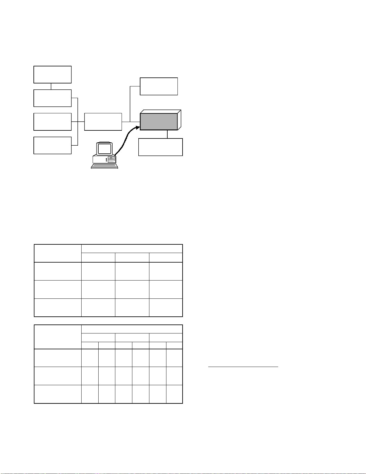
Set up the test equipment as shown below for transceiver alignment, and apply 7.5V DC power to the transceiver.
50-ohm
Dummy Load
RF Signal
Generator
Inline Wattmeter
Deviation Meter
Frequency
Counter
RF Sampling
Coupler
CT-42A connection
Cable
PC
COM port
Transceiver
MIC/EAR
Power Supply
7.5V DC
The transceiver must be programmed for use in the
intended system before alignment is attempted. The RF
parameters are loaded from the file during the alignment
process.
In order to facilitate alignment over the complete operating rang of the equipment, it is recommended that the
channel data in the transceiver be preset as per the chart
below.
Channels
Low Band Edge
(Channel 1)
Band Center
(Channel 2)
High Band Edge
(Channel 3)
Tone-Frequency (Hz) / DCS-code
Channel
Low Band Edge
(Channel 1)
Band Center
(Channel 2)
High Band Edge
(Channel 3)
Ver. AS1 Ver. D Ver. F
400.000 450.000 485.000
415.000 467.500 498.500
430.000 485.000 512.000
Ver. AS1 Ver. D Ver. F
CTCSS
– – – – – –
151.4 – 151.4 – 151.4 –
– 627 – 627 – 627
Frequency (MHz)
DCS
CTCSS
DCS
CTCSS
DCS
The alignment tool outline
Installation of the Alignment tool
The “alignment mode” is a software-based protocol,
accessed by an “Alignment Mode” command from the
computer while switching the transceiver on.It is operated by the alignment tool automatically. During use of
the alignment mode, normal operation is suspended. The
alignment tool program provides all needed operation capability.
The alignment tool consists of an executable file
“CE44.exe” and an accmpanying configuration file
“CE44.cfg” which should be loaded per standard DOS
procedures. Create a suitable directory, then copy these
foles from the distribution diskette into the new directory.
For example, if copying the file from Drive A, use the
following DOS command sequence:
c:\ mkdir align [enter]
c:\ cd align [enter]
c:\ align\ copy a:ce44.*
No further installation steps are required. If you wish
to utilize a different name for the alignment directory, it
will not matter to the executable file.
Booting the Alignment Tool
Change to the “align” directory (or the directory name
you utilized in the previous section). Now type on the
command line: ce44 [ENTER] to boot the alignment tool.
The introductory screen will appear, and you may press
any key to enter the main screen.
Entering Alignment Mode
To enter the alignment mode, turn the transceiver off,
Select “Radio” then “Adjust” parameter. Now, turn the
transceiver back on. When the command has been successful, a message on the computer screen will confirm
that the transceiver is now in the “Alignment” mode.
Alignment Sequence
Although the data displayed on the computer's screen
during alignment is temporary data, it is important you
follow the basic alignment sequence precisely, so that the
displayed data and the data loaded into the transceiver are
identical.
Basic Alignment Sequence
1. Enter the alignment mode
2. Upload data from transceiver
3. Align data
4. Download data to transceiver
Page 3

Alignment
PLL VCV (Varactor Control Voltage)
r Connect the DC voltmeter between TP3 on the Main
Unit and ground.
r Set the transceiver to CH 3 (high band edge), and ad-
just L1004 on the Main Unit for 4.0 V (± 0.1 V) on
the DC voltmeter.
r Set the transceiver to CH 1 (low band edge), and con-
firm the low-end VCV is more than 1.1 V while transmitting, and also while receiving.
Transmitter Output Power
r Set the transceiver to CH 2 (band center).
r Open the “Adjust” window on the CE44 program, then
select the “RF Power (High)” or “RF Power (Low)”
parameter.
r Press the [ENTER] key to enable programming of this
parameter; use the
power meter reading is 5.0 W (± 0.1 W) (for “RF Power
High”) or 1.0 W (± 0.1 W) (for “RF Power Low”).
Confirm that the current consumption is 2.2 A or lower
(for “RF Power High”) or 1.0 A or lower (for “RF
Power Low”).
r Press the [ENTER] key to lock in the new data.
[¡]
or
[¢]
arrow keys so that the
MIC Sensitivity
r Set the transceiver to CH 2 (band center).
r Inject a 1 kHz tone at –37 dBm to the MIC jack.
CLONE GND
SP
IN
r Open the “Adjust” window on CE44, then select the
“MIC Sensitivity” parameter.
r Press the [ENTER] key to enable programming of this
parameter; use the
deviation meter reading is ±3.0 kHz (±0.1 kHz) (for
25 kHz steps) deviation.
r Press the [ENTER] key to lock in the new data.
[¡]
or
[¢]
arrow keys so that the
TP03 L1004
Page 4

Alignment
MAX Deviation
r Set the transceiver to CH 2 (band center).
r Inject a 1 kHz tone at –17 dBm to the MIC jack.
r Open the “Adjust” window on CE44, then select the
“MAX Deviation” parameter.
r Press the [ENTER] key to enable programming of this
parameter; use the
deviation meter reading is ±4.2 kHz (±0.1 kHz) (for
25 kHz steps) or ±2.1 kHz (±0.1 kHz) (for 12.5 kHz
steps) deviation.
r Press the [ENTER] key to lock in the new data.
[¡]
or
[¢]
arrow keys so that the
CTCSS Deviation
r Set the transceiver to CH 2 (band center).
r Open the “Adjust” window on CE44, then select the
“CTCSS Deviation” parameter.
r Press the [ENTER] key to enable programming of this
parameter; use the
deviation meter reading is ±0.8 kHz (±0.1 kHz) (for
25 kHz steps) or ±0.5 kHz (±0.1 kHz) (for 12.5 kHz
steps) deviation.
r Press the [ENTER] key to lock in the new data.
[¡]
or
[¢]
arrow keys so that the
DCS Deviation
r Set the transceiver to CH 3 (high band edge).
r Open the “Adjust” window on CE44, then select the
“DCS Deviation” parameter.
r Press the [ENTER] key to enable programming of this
parameter; use the
deviation meter reading is ±0.8 kHz (±0.1 kHz) (for
25 kHz steps) or ±0.4 kHz (±0.1 kHz) (for 12.5 kHz
steps) deviation.
r Press the [ENTER] key to lock in the new data.
[¡]
or
[¢]
arrow keys so that the
RF Frequency
r Set the transceiver to CH 2 (band center).
r Open the “Adjust” window on CE44, then select the
“RF Frequency” parameter.
r Press the [ENTER] key to enable programming of this
parameter; use the
frequency counter displays the band center frequency
(±100 Hz) for the version being aligned.
r Press the [ENTER] key to lock in the new data.
[¡]
or
[¢]
arrow keys so that the
Sensitivity
r Set the transceiver to CH 3 (high band edge).
r Tune the RF signal generator to the same frequency as
the transceiver’s, then set the generator output level to
40 dBµ with ±3.0 kHz deviation @ 1 kHz tone modu-
lation.
r Open the “Adjust” window on CE44, then select the
“RX Tune” parameter.
r Press the [ENTER] key to enable programming of this
parameter. Use the
best sensitivity; ultimately, the radio should be aligned
so that the RF signal generator output level is –6 dBµ
EMF (0.25 µV) or less for 12 dB SINAD.
r Press the [ENTER] key to lock in the new data.
[¡]
or
[¢]
arrow keys to tune for
 Loading...