

Page 1
Page 3-1
ALIGNMENT PROCEDURES
ALIGNMENT PROCEDURES (Continued)
:37
789
Operating Conditions
Unless otherwise noted, the following conditions must be
observed when aligning the ITC222 chassis:
Chassis must be operated from a 120VAC isolation
transformer, with line voltage set to 120VAC (±2.0V).
Picture controls (black level, contrast, etc.) must be set to
factory presets via the Picture Quality menu.
Procedures must be performed in the sequence given.
A 10X probe must be used for oscilloscope and frequency
measurements.
The audio output leads must not be shorted together or to
ground with the chassis on.
All video signals must have -40 IRE sync tips unless specified
otherwise.
Chassis AC power must be removed for 10 seconds before
disconnecting any cable.
A 3-minute warm-up is required for chassis or module related
alignments. A 15-minute warm-up is required for Kine or
Convergence related alignments.
Required Test Equipment
- Dual-Trace Oscilloscope
- Digital Voltmeter
- Frequency Counter
- Audio Signal Generator
- NTSC Signal Generator (B&K 1249, or equivalent)
- MTS Signal Generator (B&K 2009, or equivalent)
- Sweep/Marker Generator (or Standard Signal
Generator)
- YPrPb Signal Generator (DVD player w/YPrPb)
- DC Power Supply (5.0V/0.25A) for TAG001
- Chipper Check® software
- Chipper Check® interface box and computer
- Personal Computer (IBM Compatible w/ CD ROM and
Sound Card)
NOTE: For optimum performance it is critical that this in-
strument be properly aligned. For Auto Convergence
to work correctly it is HIGHLY RECOM-
MENDED that the geometry alignments are first
verified
Small Signal Board (SSB) Replacement
All alignment data is stored in EEPROMs located on the
Small Signal Board (SSB). If the SSB needs to be replaced,
it is HIGHLY RECOMMENDED the EEPROM data be
downloaded by using Chipper Check. Once the SSB has
been replaced, upload the alignment data back into the
instrument. Then verify that the instrument is properly
aligned.
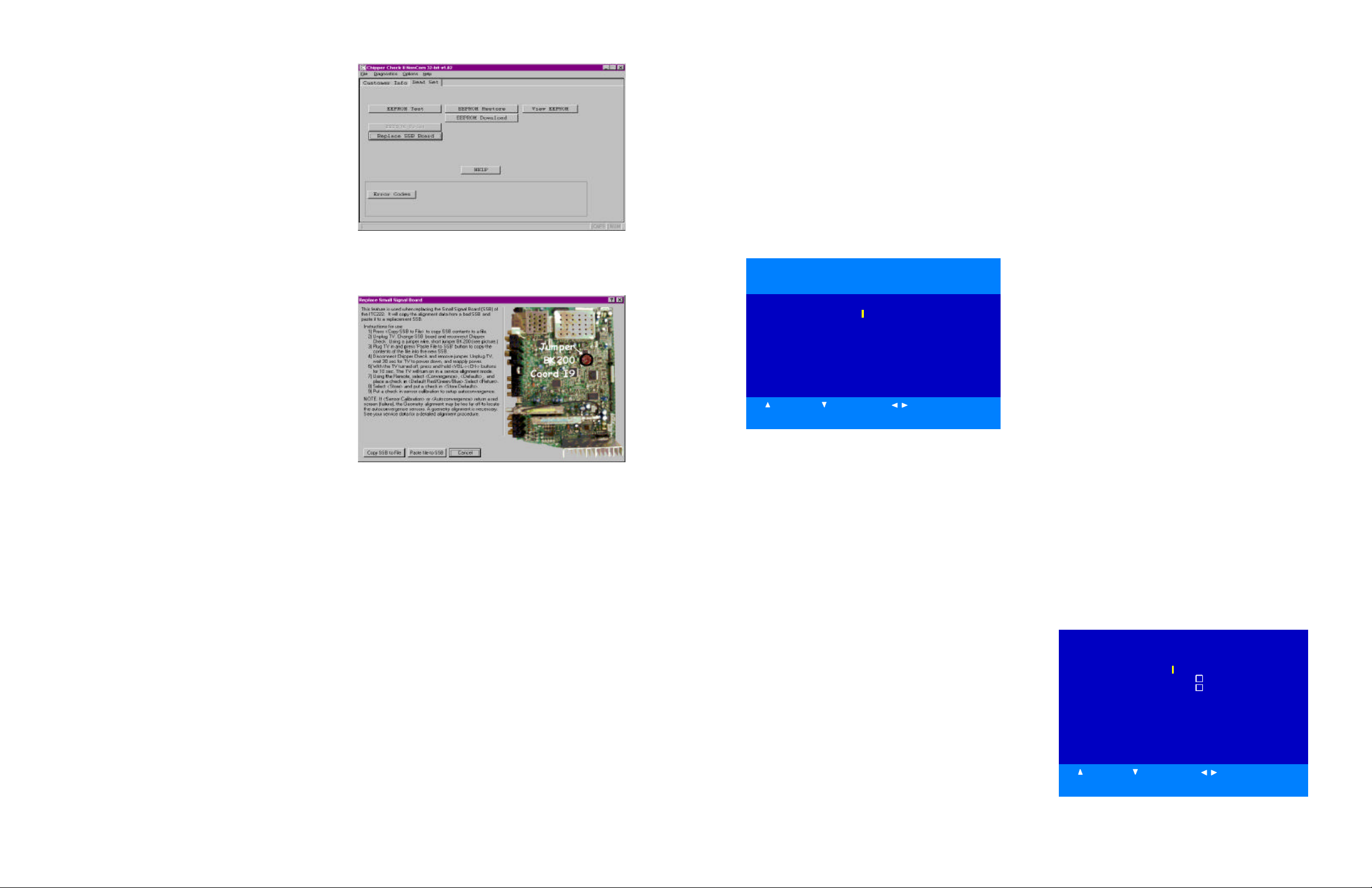
1. Open Chipper Check. Select “Dead Set” “ITC222”.
Follow the On Screen Instructions to establish a connection. Fill in the Customer Information on the “Customer
Info” tab and change to the EEPROM tab.
The following menu should appear.
2. Press the “Replace SSB Board” The following screen
appears
3. Chose “Replace SSB Board Procedure”. Follow the instructions on this screen to copy the alignment data from
the defective SSB to the new SSB.
NOTE: It may be necessary to perform the geometry align-
ment to get the auto convergence to work correctly.
Please refer to the section on Geometry Alignments
CRT Replacement (PTV Models)
If only 1 or 2 CRT’s are replaced use a convergence pattern
to align the new CRT. Align the new CRT to the pattern
generated by the existing CRT by adjusting the Yoke and
Centering Rings. Then run Auto Convergence. If all 3 CRT’s
are replaced, it will be necessary to first center the Green
CRT using a pattern with a center dot. Then align Red and
Blue following the Geometry Alignment procedures.
Service Mode
Most of the alignments for this chassis are software-driven.
Those alignments must be accessed and modified
through the front panel service mode.
Entering the TV Service Mode Using the Front Panel
Controls
1.
Press and release the
POWER button to turn the
instrument off.
2. Wait 10 seconds before trying to enter the Field Service
Mode.
3. Press and hold the VOLUME DOWN and CHANNEL
DOWN buttons for at least 8 seconds.
4. The instrument will switch on and come up with the field
service main menu on the screen. LED will illuminate
before the picture comes up.
The instrument should display the following menu:
Soft-Ver. ITC222_V100-0 000046
DVD Soft-Ver. 3.12
Config. W - - V - - -P - Serial-No. AMN456
QUIT
TUBE
CHASSIS SETUP
FEATURE SETUP
GEOMETRY
VIDEO
EVENT HISTORY
SOUND
MISCELLANEOUS
CONVERGENCE
DVD
UP DOWN
SELECT
Main Menu
The
CH /\ and CH \/ buttons on the front panel are used
to navigate up or down in the menu.
The VOL + and VOL - buttons on the FPA are used to
select a menu item or decrease or increase a value in a
selection list.
The remote control can also be used to navigate the field
NOTE: Before the Field Service Mode is exited; you must
service mode.
check STORE or all changes to alignments will be
• Clear button: When this button is pressed the Field
lost.
Service Mode disappears and the every-day TV
functions are available.
• Menu button: To re-enter the Field Service Mode,
make a long press on the Menu button. The service
technician re-enters in the same menu point where
he left the Field Service Mode.
• ∧: This button is used to navigate up in the menu.
• ∨: This button is used to navigate down in the menu.
• <: This button is used to select a menu item, to
decrease a value or to select the previous value in a
selection list.
• >: This button is used to select a menu item, to
increase a value or to select the next value in a
selection list.
• OK: This button is used to select or deselect a
menu item.
Main Menu
Soft-Ver: Displays the current software version.
Runtime Counter: Displays the total runtime in
hours and mintues.
DVD Soft-Ver: For DVD models only, displays the
current software version.
Config: Displays the configuration code of the
instrument. Each character represents a paraticular
hardware feature or option.
Serial-No.: Displays the serial number of the
instrument.
Common features found in the submenus
Return: The submenu is closed and the main Field
Service Mode menu appears.
Defaults: The default values for the current menu
are copied from ROM to RAM.
Note: If Default is checked a complete realignment of
that particular menu is required.
Store: All current values from a menu group are
stored into memory.
Restore: The last stored settings for the menu
displayed are copied from NVM to RAM.
Tube Type Menu
1. Select the correct tube type from a pulled down
list on the right hand side of the menu. (This
will activate new tube type values along with
default video and geometry parameters)
2. Check STORE to save new parameters in
memory.
TUBE
Return
Tube Type RP 16x9
Store
Restore
UP DOWN SELECT
Tube Submenu
Page 3-2
Page 2
Page 3-4
Page 3-3
ALIGNMENT PROCEDURES (Continued)
Chassis Setup
ALIGNMENT PROCEDURES (Continued)
Subwoofer: Allows the instrument to be configured for
a subwoofer
Pict. Rotation: Specifies whether the picture rotation
option is available or not. (DV Models Only)
Autoconvergence: Specifies whether the
autoconvergence option is available or not. (PTV Models
Only)
DVI: Specifies whether the DVI option is available or
not.
Toplight: Specifies whether the toplight option is
available or not.
CHASSIS SETUP
Return
Subwoofer
Pict. Rotation
Autoconvergen ce
DVI
Toplight
Defaults
UP DOWN SELECT
Chassis Setup Submenu
Feature Setup
Curtains Effect: Determines if the curtains feature is
available to the user.
Opt. Still Pict. : Determines if the Optimised Still Picture
feature is available to the user.
Auto Film Mode: Determines if the Automatic Film
Mode Detection feature is available to the user.
Burn-In Prot. : Determines if the Burn-In Protection
feature is available to the user.
FEATURE SETUP
Return
Curtains Effect
Opt. Still Pict.
Auto Film Mode
Demo Mode
Burn-In Prot.
Welcome/Contact
Program Info
Defaults
UP DOWN SELECT
Feature Setup Submenu
Geometry Alignment
Entering the Geometry menu the display mode must be
set to Standard Scanning Mode (480i/480p and 1080i).
All 480i/480p alignments should be completed using the
RF input. Use either component input or DVI-input for
1080i adjustments.
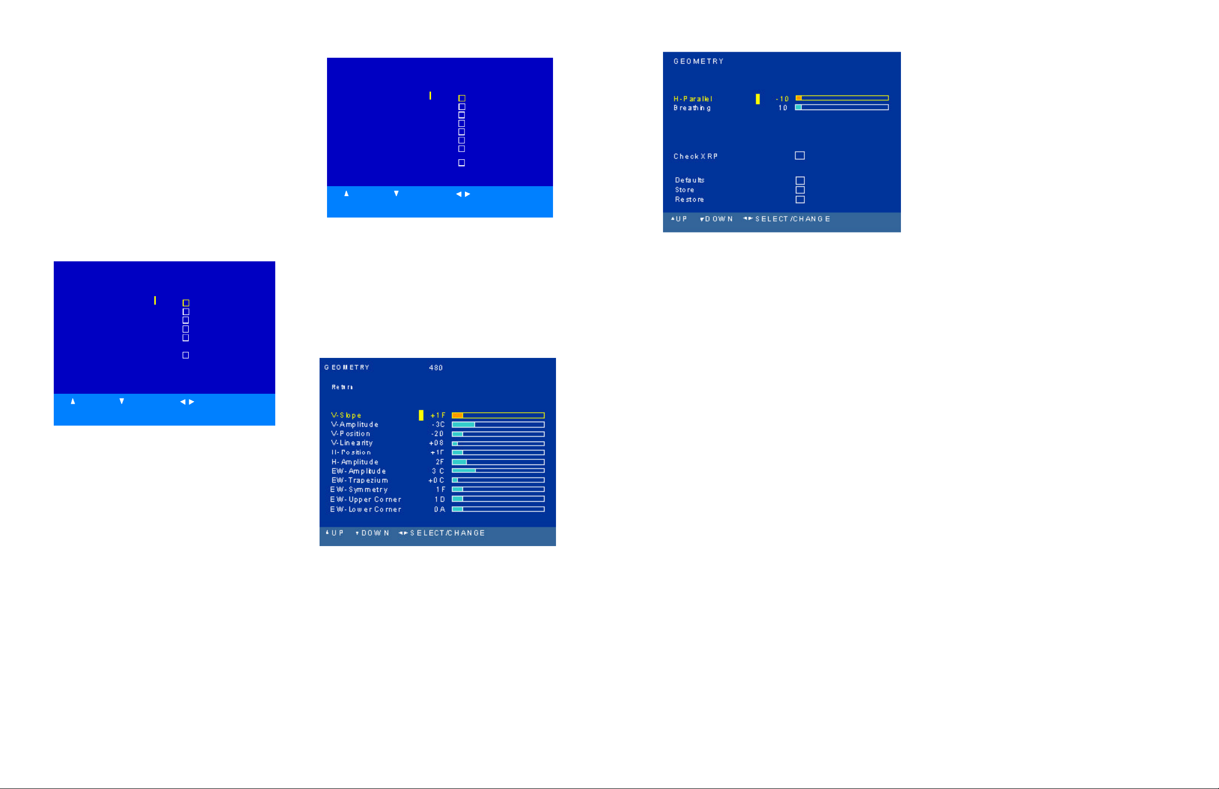
Geometry Submenu
Alignment Procedure (Direct View Models Only)
NOTE: Unless otherwise noted all Geometry adjustments
must performed in both 480i/p and 1080i modes.
1. Place the instrument in the Field Service Mode.
2. Enter the Tube submenu. Verify the correct tube type
is selected.
3. Enter the Geometry submenu.
4. Adjust H-Amplitude (Horizontal Amplitude) for slight
underscan.
5. Enter the Video submenu. Selct the G2 alignment.
Adjust the Screen control on the flyback until the just
becomes visible.
Geometry Submenu
6. Adjust PL557 on the Dynamic Focus Board to center the
raster between the tube border.
7. Realign G2 for 150V on the highest cathode.
8. Tune the instrument to receive a crosshatch pattern.
9. Return to the Geometry submenu.
10. Adjust V-Slope (Vertical Slope) until the middle line of
the test pattern is just visible. (Not used in 1080i)
11. Using a Monoscope pattern, adjust V-Amplitude (Vertical Amplitude) until the first and last horizontal line of
the test pattern is just hidden by the tube.
NOTE: Instruments with 16/9 CRT’s must have this
alignment performed with the format set to 16/9.
12. Adjust V-Position (Vertical Position) until the picture is
centered vertically. It may be necessary to recheck the VAmplitude (Step 11) adjustment.
13. Adjust V-Linearity (Vertical Linearity) for equal height
of the squares in the crosshatch pattern.
NOTE: Instruments with 16/9 CRT’s must have this
alignment performed with the format set to 16/9.
14. Adjust H-Position (Horizontal Position) until the test pattern is horizontally centered.
15. Using a Monoscope pattern adjust H-Amplitude (Horizontal Amplitude) until the first and last horizontal line of
the test pattern is just hidden by the tube. It may be necessary to recheck the H-Position (Step 14) adjustment.
16. Using a Crosshatch pattern adjust EW-Amplitude (East
West Amplitude) until the vertical lines in the middle of
the CRT are straight.
17. Adjust EW-Upper Corner (East West Corner) until the
vertical lines are straight at the top of the screen.
18. Adjust EW-Lower Corner (East West Corner) until are
straight at the bottom of the screen.
19. Adjust EW-Symmetry (East West Symmetry or H-Bow)
until the left and right border of the screen are the same.
NOTE: It may be necessary to repeat Steps 14- 19 after this
adjustment for optimum performance.
20. Adjust H-Parallel (Horizontal Parallelogram) the offset
between the top and bottom of the picture.
21. Adjust EW-Trapezium (East West Trapezium) for best
compromise between Left and right vertical lines.
22. Adjust Breathing (EHT Compensation) until horizontal
amplitude will change with different beam current at the
same ratio as vertical amplitude.
23. H-Max and H-M set the range limitations of the H-Amplitude adjustment. This adjustment should only be used
in cases where CRT is replaced and it does not appear in
the CRT list. To access this adjustment, the Development Support must be checked in the Miscellanous Setup
menu.
24. To check the box to set the shutdown threshold for the
XRP circuitry, hold down the “OK” button for
approxomately 5 seconds. During this automatic process
the screen will blank, then reappear once it is finished.
25. Before exiting the Geometry menu, check Store to save
changes to memory.
26. After the Geometry Alignments, check the Earth-Field
Compensation (EFC) adjustment (DV Models Only). Enter the Advanced Picture Setting Menu. Using a crosshatch pattern, adjust the EFC for minimum picture rotation at the top and bottom.
Alignment Procedure (Projection Models Only)
NOTE: Unless otherwise noted all Geometry adjustments
must performed in both 480i/p and 1080i modes.
1. Place the instrument in the Field Service Mode.
NOTE: It is recommended the Geometry alignments be
performed using the Green CRT only.
2. Enter the Tube submenu. Verify the correct tube type is
selected.
3. Tune the instrument to receive a crosshatch pattern.
4. Return to the Geometry submenu.
5. Adjust V-Slope (Vertical Slope) until the middle line of
the test pattern is just visible. (Not used in 1080i)
6. Exit the Geometry submenu and turn the instrument OFF.
Disconnect the Convergence Yoke connectors BW001
and BW002 (Located in lower right corner of the Convergence Amplifier PCB). Turn the instrument ON and
tune to receive a center line pattern. Adjust horizontal
and vertical center lines according to the chart below
with the static convergence magnets. When completed
turn the instrument OFF and reconnect the convergence
yoke connectors.
Page 3
Kine
Socket
Phosphor
ALIGNMENT PROCEDURES (Continued)
ALIGNMENT PROCEDURES (Continued)
Page 3-5
Page 3-6
Screen Size
40" 2.4 cm (0.94 in) 2.4 cm (0.94 in)
52" 3.1 cm (1.22 in) 3.1 cm (1.22 in)
56" 3.3 cm (1.29 in) 3.3 cm (1.29 in)
61" 3.5 cm (1.37 in) 3.5 cm (1.37 in)
Red Center Line
Set Left of Center
Blue Center Line
Set Right of Center
7. Place in the Field Service Mode. Enter the Geometry
submenu. Using a Monoscope pattern, adjust V-Amplitude (Vertical Amplitude) until the first and last horizontal line of the test pattern is just hidden by the tube.
8. Adjust V-Position (Vertical Position) until the picture is
centered vertically.
9. Adjust V-Linearity (Vertical Linearity) for equal height
of the squares in the crosshatch pattern.
10. Adjust H-Position (Horizontal Position) until the test pattern is horizontally centered.
11. Using a Monoscope pattern adjust H-Amplitude (Horizontal Amplitude) until the first and last horizontal line
of the test pattern is just hidden by the tube.
12. Using a Crosshatch pattern adjust EW-Amplitude (East
West Amplitude) until the vertical lines in the middle of
the CRT are straight.
13. Adjust EW-Trapezium (East West Trapezium) for best
compromise between Left and right vertical lines.
14. Adjust EW-Symmetry (East West Symmetry or H-Bow)
until the left and right border of the screen are the same.
NOTE: It may be necessary to repeat Steps 10- 14 after this
adjustment for optimum performance.
15. Adjust Breathing (EHT Compensation) until horizontal
amplitude will change with different beam current at the
same ratio as vertical amplitude.
16. H-Max and H-M set the range limitations of the H-Amplitude adjustment. This adjustment should only be used
in cases where CRT is replaced and it does not appear in
the CRT list. To access this adjustment, the Development Support must be checked in the Miscellanous Setup
menu.
17. Check the box to set the shutdown threshold for the XRP
circuitry by holding down the “OK” button for 5 sec.
During this automatic process the screen will blank, then
reappear once it is finished.
18. Before exiting the Geometry menu, check Store to save
changes to memory.
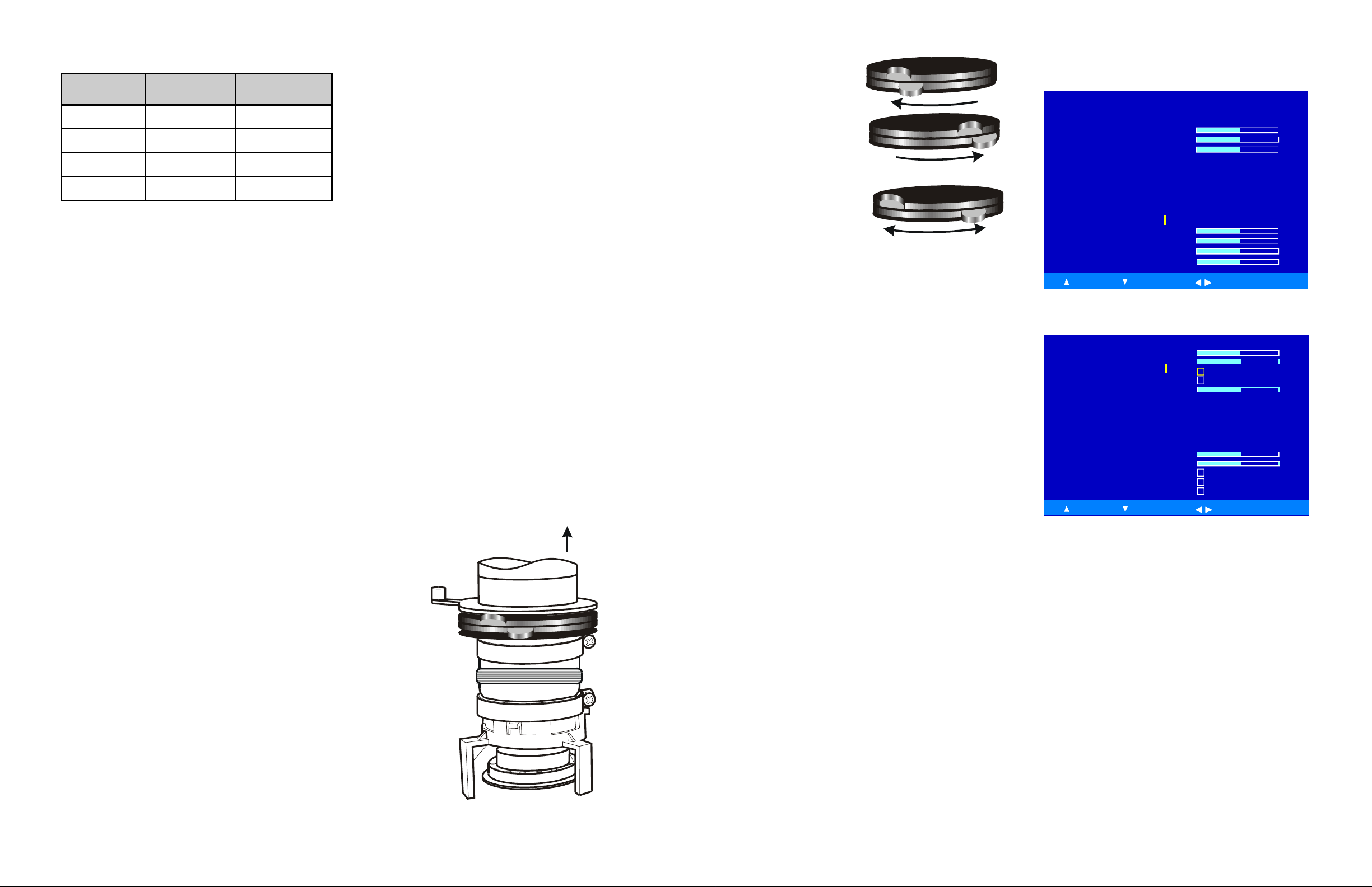
Yoke Centering Ring Adjustment
If Chipper Check is not available it is possible to replace a
single CRT and realign geometry by using the centering rings
on the CRT.
Using the convergence pattern available when in service
menu the pattern from the replacement CRT may be adjusted
to align with either of the two remaining CRT's using the centering rings shown in Figure 1.
First make certain the replacement CRT and yoke are assembled and placed back in the mounting as close as possible
to the original CRT and yoke. At this point having the convergence pattern on screen will assist in the mechanical mounting.
Using the centering rings and observing the convergence
pattern, rotate and move the pattern until the replacement color
overlays as close as possible to the two colors not replaced.
Moving the ring tabs together around the neck of the CRT
draws the raster in small circles. Spreading the tabs apart
moves the raster in more linear angles. The closer the tabs
are together, the less affect on the CRT beam they have.
When the raster is as close as possible fix the magnets with
paint or nail polish to prevent further movement.
After fixing the magnets, if gross geometry errors are apparent, geometry alignment is indicated. If the raster is close,
use the "Auto-convergence" feature provided in the consumer
menu to re-align convergence. This should correct most minor geometry problems. Follow auto-convergence with the
consumer red and blue centering adjustments, then evaluate
the raster again.
In most cases convergence will now be acceptable. If only
slight convergence errors are noted the technician should enter the manual digital convergence menu and begin "touchup" of the screen.
If gross geometry errors are still apparent re-evaluate
whether the errors are noticable on the replacement CRT or
whether they are global, affecting all three CRT's. If the errors affect all three CRT's a full geometry alignment is indicated. If the errors only affect one CRT, particulary the replacement, return to the mechanical placement and centering
ring adjustments and begin those procedures again.
Screen
Centering
SVM Yoke
Figure 1 - Centering Rings
Rotate Tabs Together
Spread Tabs Apart
Figure 2 - Centering Ring Tab Movement
Focus Adjustments
Before attempting the Focus Adjustments, allow the
instrument to warm up for a minimum of 15 minutes.
Dynamic Focus CRT (DV Models Only)
1. Tune the instrument to receive a crosshatch pattern.
2. Turn the F1 (Static) control on the focus block fully clockwise
3. Adjust the F1 control while observing the vertical lines
along the left side of the screen for best possible focus.
4. Turn the F2 (Dynamic) control on the focus block fully
clockwise.
5. Adjust the F2 control while observing the horzontal lines.
Adjust for best possible focus.
6. Repeat step 3 and 5 for best possible overall focus.
Single Focus CRT (DV Models Only)
1. Tune the instrument to receive a crosshatch pattern.
2. Turn PL501 (Located on the Dynamic Focus PCB) to the
full counter clockwise position.
3. Adjust F2 on the focus block for best possible focus of the
horizontal lines.
4. Adjust PL501 for best possible focus of the vertical lines.
5. Repeat steps 3 and 4 for best possible overall focus.
Focus Adjustment (PTV Models)
1. Tune instrument to receive a crosshatch pattern.
2. Preset Contrast to maximun.
3. Adjust each CRT separately. Cover the two CRT’s not being adjusted and adjust for best overall focus.
5. Adjust the Green Electrical Focus control, located behind
the speaker grill for best overall focus.
6. Repeat procedure for the Red and Blue CRT’s.
Video Alignments
VIDEO PA L RF - BG
Return
Peak White
Whitepoint R
Whitepoint G
Whitepoint B
G2 Alignment
Scaling Colour
Scaling Brightness
Cut off R
Cut off G
UP D OWN SELECT/CHANGE
VIDEO PAL RF - BG
Scaling Contrast
Scaling Tint
Contrast max
Drive Loop Disable
Text Contrast
Full White 4/3
Drive Level
Defaults
Store
Restore
UP DOWN SELECT/CHANGE
D4
80
F0
40
- 22
78
+90
D4
80
-18
- 22
78
Video Alignment Submenu
Before attempting the Video Alignments, allow the
instrument to warm up for a minimum of 15 minutes.
1. Tune the instrument to receive a crosshatch
pattern.
5. Place the instrument in the Field Service Mode.
6. Enter the Video submenu.
7. Select G2 adjustment.
8. Adjust Screen control until retrace lines become
visible, then adjust to make retrace lines invisible.
9. Press any key to exit the G2 alignment mode.
10. Select a pluge test pattern. Pattern should have a
0% background with a -2% and +2% bar.
11. Adjust Scaling Black Level to make the -2% bar
invisible, keeping the +2% bar visible.
Page 4

Page 3-7
ALIGNMENT PROCEDURES (Continued)
ALIGNMENT PROCEDURES (Continued)
12. Select a 75% color bar test pattern.
13. Connect a scope to the Blue Cathode of the CRT
board.
14. Adjust the Scaling Color to the levels shown
below.
For these adjustments this bar and the next brighter
bar will be used. On most patterns the remainder of
the bars will progressively become brighter.
2. Adjust Black Cutoff R or Black Cutoff G until any
tinting disappears from the black bar. When properly
adjusted the adjacent bar should be a very low level
gray with no color tinting.
3. Now observe the brighter portions of the bars.
Adjust Whitpoint R, G, or B to remove any signs of
tint in the higher brightness bars. Observe the bars
for signs of CRT overdrive. Some compromise may
be required, but the higher IRE bars should be as
free from color tinting as possible.
Note: There are separate color temperature alignments for
RF (NTSC), Comp 1H, Comp 2H, DVI and
AUX_RGB (If unit has DVD option installed).
2. Adjust for peak white.
3. Contrast Max and Scaling Contrast are preset
according to the CRT type selected and do not need
to be adjusted.
Event
If a run-time event occurs, its error code will be stored in
the NVM. The stored event codes can be read in one of two
methods. The first is with the event menu. The last five
event codes will be displayed, along with a time stamp
from the run time counter. The time stamp will display the
last occurrence of a particular event. The time stamp is
displayed as “Run Hours”. An event counter counts how
many times that event has occurred. The counter will not
count beyond 255. The most recent event code is displayed
on top. To clear the event codes from memory, select the
Clear Event Codes box. A long press will clear all stored
codes.
Note: This alignment must be performed in each of the
following modes, Tuner, Comp 1H, Comp 2H, DVI
and AUX_RGB (if DVD option is installed).
16. The Drive Level Alignment is preset according to
the CRT type selected and does not need to be
adjusted.
17. Before exiting the Video Alignment Submenu, check
Store to save all alignments.
Color Temperature (Overview)
Color Temperature for the ITC222 is similar to past chassis.
Some form of staircase pattern similar to the figure below is
required. Proper identification of the “0” (if available) and
“7.5” or “setup” bars on screen and the waveform produced
on the cathodes of the CRT will be needed. Consult the
specifications manual for the pattern generator used to
confirm the location of these bars.
The oscilloscope waveform shows the relationship between
the bars and the video signal at the cathodes of the CRT.
This waveform is present on all three cathodes. With the
oscilloscope adjusted to provide a full peak to peak readout
of the waveform at the horizontal rate, the 7.5 IRE setup
bar will the critical area. Be certain this bar can be identi
fied using the equipment available. If a 7.5 IRE bar is not
available, 10 IRE may be used.
It should be noted that bar patterns differ. Some vary from
10 to 100 IRE in various steps and in different directions,
but most should have an identifiable 7.5 to 10 IRE bar.
The purpose of the color temperature setup is to assure
uniform gray level from black to the brightest scenes. If a
uniform gray screen is displayed, no matter the brightness
level, no tinting in either red, green or blue direction should
be apparent. This is known as “color tracking”. Once the
proper color temperature is set, AKB will maintain the
cutoff of the CRT to assure proper low light performance.
Black Cutoff R/G, Whitepoint R/G/B Setup
(Recommended Method)
1. Apply a gray test pattern giving a 12 IRE flat
window. Connect Colorimeter near the center of
the screen.
2. Adjust Black Offset R and Black Offset G to
obtain the following color coordinates.
Direct View Projection TV
X 0.282 0.283
Y 0.298 0.296
3. Apply a gray test pattern giving a 50 IRE flat
window.
4. Adjust Whitepoint R, G, and B for the following
color coordinates.
Direct View Projection TV
X 0.282 0.278
Y 0.298 0.291
Note: This alignment must be done in the following
modes, RF (NTSC), Comp 1H, Comp 2H, DVI
and AUX_RGB (If unit has DVD option
installed).
Black Cutoff R/G, Whitepoint R/G/B Setup
(Alternative Method)
1. Apply a vertical gray bar staircase pattern (at least
8 bars from “7.5” to “>75” IRE). Identify the 7.5
IRE bar location. It is the “black” or “cutoff” bar.
Peak White Alignment
1. Apply a white centered pattern of 100 IRE 2% of
the picture surface on a dark background.
2. Adjust for peak white at center of the screen.
3. Check Scaling Black Level, Whitepoint, Black
Offset and Peak White adjustments. It may be
necessary to adjust these alignments several times
for optimum performance.
Note: This alignment must be done in the following
modes, RF (NTSC), Comp 1H, Comp 2H, DVI and
AUX_RGB (If unit has DVD option installed).
Full White 3/4 Alignment
1. Insert a full white pattern of 100 IRE through RF.
(Instrument will automatically set to ¾ mode).
2. Adjust for full white across the screen.
Text Contrast, Contrast Max, Scaling Contrast
Alignments
1. Insert a white centered pattern of 100 IRE, 2% of
the picture surface with a black background.
Only the last error code stored in the NVM can be
read with this method. The LED will blink two separate digits.
Example, if the error code of 23 is the last error code stored
EVENT HISTORY
Return
Clear Event Codes
Code Co unt Time Stamp
11 00 1 00 0135:30
24 01 2 00 0090:10
78 00 3 00 0043:54
51 00 1 00 0001:20
00 00 0 00 0000:00
Test: Brightness Sensor: 2 Colour: R
Direction: Right Value: 125 Scan mode: 2H
UP DOWN SELECT/CHANGE
Event Submenu
in the NVM, the LED will have 2 short flashes, followed by
a short pause. Then will flash 3 times, followed by a long
pause. This will be repeated 4 times.
First allow the instrument to sit unplugged for 60 seconds.
At plug in the LED will first blink twice to indicate
microprocessor has reset. When an attempt is made to power
up, the instrument will attempt 3 times to start. The LED
will display a series of flashes followed by the error codes.
The LED will flash the error code 4 times.
Sound Setup
Effect Strength (MED): Modifies the bass effect
strength for the user setting MEDIUM.
Effect Stength (HIGH) : Modifies the bass effect
strength for the user setting HIGH.
Page 3-8
Page 5

Page 3-9
ALIGNMENT PROCEDURES (Continued)
ALIGNMENT PROCEDURES (Continued)
R e s t or e
10 80
Low Pass Frequency: Modifies the low pass cut-off
frequency.
High Pass Frequency : Modifies the high pass cut-off
frequency.
Sub-woofer Corner Frequency : Modifies the subwoofer corner cut-off frequency.
SOUND
Return
Effect Strength (MED) 80
Effect Strength (HIGH) 9A
Low Pass Frequency 80
High Pass Frequency 56
Sub-woofer Corner Frequency 80
Defaults
Store
Restore
UP DOWN SELECT/CHANGE
Sound Setup Submenu
Miscellaneous
Clear Programs:
Select with a 2 second press to clear
all programs stored in memory and set Picture
Preference, User Picture and Audio settings to factory
values. Returns the instrument to “Out of Factory Mode”.
Default Presets : Sets the default value for all factory
sound and picture presets.
Bus Quiet: In this mode the NVM can be read, modified
or reprogrammed. Enter this function with with a 2
second press. This mode is cancelled with a press of
Clear, Left, Right, Up, Down or On-Off keys.
Development Support : Enables or Disables access to
development support functions in the field service
menus.
Restore Factory Settings : Restores the correct “Out
of Box” condition.
Switch 2nd Tuner to Main : Causes the current signal
on the 2nd tuenr to be switched to the main screen and
the monitor output jacks. Any channel change will
override this feature and return tuning to normal.
MISCELLANOUS
Return
Clear Progs
Default Presets
Bus Quiet
Development Support
Restore Factory Settings
FFI Bit
Switch 2nd tuner to main
UP DOWN SELECT
Miscellaneous Setup Menu
Convergence (PTV Models Only)
Overview
The ITC222 employs a ditigal convergence circuit that makes
it possible to electronically align up to 208 separate points
on the screen. 3 levels of convergence adjustment is provided.
Level 1: Provides 9 adjustment points
Level 2: Provides 25 adjustment points
Level 3: Provides 195 adjustment points
CONVERGE NC E AL I G NM E N T
Ret u r n
Le vel
1 (3 x 3 )
Le vel
2 (5 x 5 )
L e v e l
3 ( 1 5 x
1 3 )
S e n s or c a l i br a t i o n
A u t o c o n v er ge nc e
Def a ul t s
St or e
U P
D O W N
S E L E C T / C H A N G E
Convergence Submenu
It is recommended to adjust Levels 1 and 2 only if repairs
have been made to the Convergence Signal circuitry or after
CRT replacement. Before performing the Convergence
Alignment procedure it is HIGHLY RECOMMENDED the
Geometry Alignment of the instrument is checked.
Note: Alignments must be performed in order. If Level 3
is adjusted, prior to Levels 1 or 2, all Level 3
7. Select “Return” to exit the Convergence Alignment
Menu.
alignments will be lost.
Note: This procedure must be performed in both the 480P
and 540P (1080I) modes. The initial service menu
In Level 1 and 2, Press OK to select the color to be
aligned. The position of the adjustment point can adjusted
screen will indicate which mode the instrument is
in.
using the navigation keys (up, down, left and right) on the
remote. Press the 2 key of the remote to move to the next
adjustment point. Press the EXIT/CLEAR key to exit
when completed.
DVD (DVD Models Only)
1. Place the instrument in the Field Service Mode.
2. Enter the DVD submenu.
3. Activate DVD Factory Mode by selecting the box. Press
Level 3 alignment works simular to Levels 1 and 2. The
only difference, to move to the next adjustment point press 2
(up), 8 (down), 6 (right) and 4 (left) on the remote unit.
when completed with convergence, press STORE to save all
changes.
Sensor Calibration is used to calculate a reference border
for the autoconvergence photo sensors. Check the box to
begin the process. Autoconvergence starts the
autoconvergence process.
Defaults enters a default submenu. Checking the box loads a
and hold the OK button for at least 2 seconds. The screen
will then show the menu shown below. This process may
take several seconds.
1. Place the instrument in the Field Service Mode.
2. Enter the DVD submenu.
DVD
Return
Activate DVD Factory Mode
A 2 second press on the OK key will cause the
TV to put the internal DVD into factory mode.
This may take a few seconds. When completed
the DVD field service commands will be available.
set of default values from the convergence backup NVM to
the Convergence IC RAM. The box will remain checked until
the value is changed or store or restore is pressed in the
convergence submenu.
UP DOWN SELECT
Note: Before the Convergence Alignement menu is exited,
you must check Store or all settings will be lost.
DVD Submenu
Manual Convergence Procedure
1. Turn instrument “On”. Allow to warm up for 20
munitues. Turn instrument “Off”. Enter the Service
Menu holding the “Channel Down” and “Volume
3. Activate DVD Factory Mode by selecting the box. Press
and hold the OK button on the remote for at least 2 seconds. The menu will then change to the menu shown below. This process may take several seconds.
Down” on the FPA for 8 seconds. Enter the
“Convergence Menu”.
2. Perform “Level 3” (and/or Level 1, Level 2) manual
convergence as describe above. When completed,
press “Clear”, then select “Return” to go back to
the main Convergence Alignment Menu.
3. Check “Store” in the main Convergence Menu. A
check mark will appear in the box.
4. Select “Defaults” to enter the Default Menu.
DVD
Return
Activate DVD Factory Mode
Restore Factory Settings
OSD to Video Ratio Normal...
Test Pattern 1 - 5 2...
Start SW update
5. Select “Store Defaults”. Press and hold OK on the
Remote for 2.5 seconds. Then select “Return” to
go back to the main Convergence Alignment Menu.
6. Perform “Sensor Calibration”. Select it and press
UP DOWN SELECT
“OK”.
Note: If the Sensor Calibration is successful, the software
will answer by flashing a GREEN SCREEN . If the
GREEN SCREEN does not appear, turn the
instrument off and begain the convergence
procedure again.
DVD Submenu (with Factory Mode Activated)
Restore Factory Settings: This will re-initialise
the DVD’s NVM content using the system NVM.
OSD to Video Ratio: Aligns the ratio between the
Page 3-10
Page 6

ALIGNMENT PROCEDURES (Continued)
Page 3-11
ALIGNMENT PROCEDURES (Continued)
Page 3-12
DVD Video Signal and the DVD OSD Video Signal.
This is internally adjusted by the DVD and cannot be
modified.
Test Pattern 1 - 5: Provides 5 test patterns for alignment.
1. Scaling Color 75/White, 75% Color Bars
2. Cutoff Alignment, 140mVp/p
3. Drive Alignment, 455mVp/p
4. Peak White Alignment, 700mVp/p
5. Color Temperature and Peak White
Event
Code
Event Circuit Condition
11 I2C_1 Low SDA Line Data Line of I2C Bus_1 Held Low
12 I2C_1 Low SCL Line Clock Line of I2C Bus_1 Held Low
13/95 I2C_2 Low SDA Line Data Line of I2C Bus_2 Held Low
14/95 I2C_2 Low SCL Line Clock Line of I2C Bus_2 Held Low
15 I2C_3 Low SDA Line Data Line of I2C Bus_3 Held Low
16 I2C_3 Low SCL Line Clock Line of I2C Bus_4 Held Low
140/170/700/359/455mVp/p
Start Software Update: Allows the DVD software to be
update. The update is sent as a CDROM
1. Selecting this function will automantically
open the DVD and switch the instrument
to the DVD mode.
2. Place the CDROM in the instrument.
Follow the instructions provided on the
screen. Durning the update process the
display will read “Updating DVD Soft
ware”.
3. After the software update is complete, the
DVD player will reboot. This may take
several seconds to complete. Once it is
complete, the instrument will exit the
DVD Factory Mode. The display will
return to the DVD submenu.
17 I2C_4 Low SDA Line Data Line of I2C Bus_4 Held Low
18 I2C_4 Low SCL Line Clock Line of I2C Bus_4 Held Low
19 Chassis Detection HW No Valid Chassis Detected
21/22/23/24 Free Event Code
25 No ACKN Main Tuner Tuner Main Tuner Does Not Answer
26 No ACKN PIP Tuner Tuner PIP Tuner Does Not Answer
27 No ACKN IX300 Video Video Switch Does Not Answer
28 No ACKN IV300 PSI PSI IC Does Not Answer
29 PDD Bit Is Set PSI IV300 Power Down Detection
31 No ACKN IV400 Deflection IC Does Not Answer
32 POR Bit Is Set Deflection IV400 Power Down Detection
33 Safety_INT Is Active Deflection Safety Circuit Is Active
34 NHF Bit Is Set Deflection Horizontal Flyback Problem
35 NRF Bit Is Set Deflection Oscillator Is Not Locked
36 BCF Bit Is Set Deflection Tube Is Still Not Warm After Warmup Time
37 NDF Bit Is Set Deflection Vertical Problem
38
39 SL Bit Is Set Deflection Phase 1 Not Locked
41 No ACKN IA001 Audio IA001 Does Not Answer
42 RESET Bit is Set Audio The RESET Bit of IA001 Is Active
43 Not Used
44 No ACKN IA900 Audio IC Does Not Answer
45 Wrong MSP Audio Wrong MSP Is Fitted
46/47 Reserved/Not Used
48 No ACKN Main IF IF IF IC (Main Tuner) Does Not Answer
49 No ACKN PIP IF IF IF IC (PIP Tuner) Does Not Answer
XRP Bit Is Set Durning
Normal Operation
Deflection X-Ray Protection
Page 7

Event
ALIGNMENT PROCEDURES (Continued) ALIGNMENT PROCEDURES (Continued)
Page 3-13
Page 3-14
Code
51 No ACKN IV100 Upconverter IC Does Not Answer
52 POR Bit Is Set Upconverter Power Down Detection (IV100)
53 Not Used
54 No ACKN IR005 NVM IC Does Not Answer
55 No ACKN IR006 Port Expander IC Does Not Answer
56 FLS Bit Is Set Flash Info Of The HOP Occurred
57 TECI Message Failed Software Can Not Perform A System Command
58 Event Code Validation Code Validation Failed
59 Wrong GenCAM Version Used GenCAM cut 2.1 Must Be Used
61 5V Good HW Switched 5V Not Available
62 5V and 8V Good HW Switched 5V & 8V Not Available
63 Power_Fail HW Unexpected Level On Power_Fail Line Found (Mains To Low)
64 XRP Alignment HW XRP Adjustment Detected Overvoltage
Event Circuit Condition
Event
Code
92 General I2C Problem SW General Problem Of One Of The I2C Cells
93 Install Problem Of I2C Bus 1 & 2 SW Problem To Install I2C Bus Driver
94 Install Problem Of I2C Bus 3 & 4 SW Problem To Install I2C Bus Driver
95
96 Install Problem Of ADC Driver SW Problem To Install ADC Driver
97 Install Problem Of AV-Link Driver SW Problem To Install AV-Link Driver
98 Install Problem Of SDRAM Timing SW Problem To Install The SDRAM Timing
99 Watchdog SW Watchdog Was Active
Install Problem Of Port Driver Or
Event Circuit Condition
Bus Driver
SW Problem To Install The Port Driver Or I2C Bus Driver
65 XRP NVM Verify HW Write To XRP NVM Area Failed
66 XRP NVM Not Recoverable HW XRP NVM Contents Are Corrutped And Can Not Be Recovered
67 Reserved
68 5V Failed During Operation HW Switched 5V Not Available During Operation
69 H & V Sync Not Valid HW H & V Sync (For OSD) Not Present
71 No ACKN IC040 Video Frame Comb Filter IC Does Not acknowledge
72 No ACKN IX400 Video 2H Video Switch Does Not Acknowledge
73/74/75/76/77 Reserved
78 No ACKN DVD Unit DVD DVD Does Not Answer
79 DVD Ready Bit DVD DVD Ready Bit Is Set
81 No ACKN Convergence IC IK201 PTV Models Convergence IC Does Not Answer
82 No ACKN M24C32 (RP-NVM) PTV Models NVM IC Does Not Answer
83 Wrong Convergence Test Pattern PTV Models Convergence Test Pattern Is Wrong
84 Before Is Was An RP PTV Models Tube Type Is RP, But Convergence Was Not Detected
85 Convergence NVM 1 Problem PTV Models Convergence 1 NVM Data Is Wrong
86 Convergence NVM 2 Problem PTV Models Convergence 2 NVM Data Is Wrong
87 IK201 Loop Blocked PTV Models IK201 Electrical Loop Blocked
88 POR Bit Is Set PTV Models The POR Set Of IK201 Is Set
89 Convergence Power Supply Off PTV Models Convergence Power Suopply Is Not Valid
91 Watchdog Disabled SW Watchdog Function Is Disabled
 Loading...