

Page 1

Alienware Aurora R9
Service Manual
Regulatory Model: D23M
Regulatory Type: D23M002
Page 2

Contents
1 Working inside your computer..........................................................................................................5
Safety instructions.......................................................................................................................................................5
Before working inside your computer..........................................................................................................................5
Before you begin ...................................................................................................................................................5
Electrostatic discharge—ESD protection.................................................................................................................... 6
ESD field service kit ................................................................................................................................................... 6
Transporting sensitive components............................................................................................................................ 7
After working inside your computer.............................................................................................................................7
2 Removing and installing components..............................................................................................9
Inside view of your computer...................................................................................................................................... 9
System-board components....................................................................................................................................... 10
Recommended tools................................................................................................................................................. 11
Screw list...................................................................................................................................................................11
Left-side cover...........................................................................................................................................................12
Removing the left-side cover................................................................................................................................12
Installing the left-side cover..................................................................................................................................13
Top cover.................................................................................................................................................................. 14
Removing the top cover....................................................................................................................................... 14
Installing the top cover......................................................................................................................................... 14
Right-side cover........................................................................................................................................................ 15
Removing the right-side cover............................................................................................................................. 15
Installing the right-side cover............................................................................................................................... 16
2.5-inch hard drive.................................................................................................................................................... 18
Removing the 2.5-inch hard drive........................................................................................................................ 18
Installing the 2.5-inch hard drive.......................................................................................................................... 19
3.5-inch hard drive.................................................................................................................................................... 21
Removing the 3.5-inch hard drive........................................................................................................................ 21
Installing the 3.5-inch hard drive.......................................................................................................................... 22
2.5-inch hard-drive cage........................................................................................................................................... 24
Removing the 2.5-inch hard-drive cage............................................................................................................... 24
Installing the 2.5-inch hard-drive cage................................................................................................................. 25
3.5-inch hard-drive cage........................................................................................................................................... 26
Removing the 3.5-inch hard-drive cage............................................................................................................... 26
Installing the 3.5-inch hard-drive cage................................................................................................................. 26
460 W power-supply unit...........................................................................................................................................27
Removing the 460 W power-supply unit.............................................................................................................. 27
Installing the 460 W power-supply unit................................................................................................................ 29
850 W Power-supply unit.......................................................................................................................................... 32
Removing the 850 W power-supply unit.............................................................................................................. 32
Installing the 850 W power-supply unit................................................................................................................ 33
Right tron-light board.................................................................................................................................................35
Removing the right tron-light board......................................................................................................................35
2
Page 3

Installing the right tron-light board........................................................................................................................36
Processor liquid-cooling assembly............................................................................................................................37
Removing the processor liquid-cooling assembly................................................................................................37
Installing the processor liquid-cooling assembly..................................................................................................40
Coin-cell battery........................................................................................................................................................ 42
Removing the coin-cell battery.............................................................................................................................42
Installing the coin-cell battery...............................................................................................................................43
Memory modules.......................................................................................................................................................45
Removing the memory modules.......................................................................................................................... 45
Installing the memory modules............................................................................................................................ 46
Solid-state drive........................................................................................................................................................ 48
Removing the solid-state drive.............................................................................................................................48
Installing the solid-state drive...............................................................................................................................49
Single-graphics card................................................................................................................................................. 50
Removing the single-graphics card......................................................................................................................50
Installing the single-graphics card........................................................................................................................52
Dual-graphics card....................................................................................................................................................54
Removing the dual-graphics card........................................................................................................................ 54
Installing the dual-graphics card.......................................................................................................................... 57
Front bezel ............................................................................................................................................................... 60
Removing the front bezel..................................................................................................................................... 60
Installing the front bezel....................................................................................................................................... 62
Top bezel.................................................................................................................................................................. 67
Removing the top bezel....................................................................................................................................... 67
Installing the top bezel......................................................................................................................................... 68
Bottom cover.............................................................................................................................................................69
Removing the bottom cover................................................................................................................................. 69
Installing the bottom cover................................................................................................................................... 70
Processor fan and heat-sink assembly..................................................................................................................... 71
Removing the processor fan and heat-sink assembly......................................................................................... 71
Installing the processor fan and heat-sink assembly........................................................................................... 73
Processor..................................................................................................................................................................75
Removing the processor...................................................................................................................................... 75
Installing the processor........................................................................................................................................ 76
Wireless card............................................................................................................................................................ 76
Removing the wireless card.................................................................................................................................76
Installing the wireless card...................................................................................................................................77
Antennas...................................................................................................................................................................79
Removing the antennas....................................................................................................................................... 79
Installing the antennas......................................................................................................................................... 80
Front I/O-panel..........................................................................................................................................................81
Removing the front I/O panel............................................................................................................................... 81
Installing the front I/O-panel.................................................................................................................................82
Front-chassis fan.......................................................................................................................................................83
Removing the front-chassis fan............................................................................................................................83
Installing the front-chassis fan..............................................................................................................................84
Top-chassis fan.........................................................................................................................................................85
Removing the top-chassis fan..............................................................................................................................85
Installing the top-chassis fan................................................................................................................................86
Power-button board...................................................................................................................................................88
3
Page 4

Removing the power-button board.......................................................................................................................88
Installing the power-button board.........................................................................................................................89
System board............................................................................................................................................................90
Removing the system board................................................................................................................................ 90
Installing the system board.................................................................................................................................. 92
Entering the Service Tag in the BIOS setup program..........................................................................................95
3 Device drivers................................................................................................................................... 96
Operating system......................................................................................................................................................96
Downloading the audio driver....................................................................................................................................96
Downloading the graphics driver...............................................................................................................................96
Downloading the USB driver.....................................................................................................................................97
Downloading the WiFi driver..................................................................................................................................... 98
Downloading the media-card reader driver...............................................................................................................98
Downloading the chipset driver.................................................................................................................................99
Downloading the network driver................................................................................................................................99
4 System setup.................................................................................................................................. 101
System setup.......................................................................................................................................................... 101
Entering BIOS setup program.................................................................................................................................101
Navigation keys.......................................................................................................................................................101
Boot Sequence........................................................................................................................................................101
System setup options..............................................................................................................................................102
Clearing CMOS settings..........................................................................................................................................104
Clearing forgotten password................................................................................................................................... 105
5 Troubleshooting............................................................................................................................. 107
Enhanced Pre-Boot System Assessment (ePSA) diagnostics................................................................................107
Running the ePSA diagnostics...........................................................................................................................107
System diagnostic lights..........................................................................................................................................107
Recovering the operating system............................................................................................................................108
Flashing BIOS (USB key)........................................................................................................................................108
Flashing the BIOS...................................................................................................................................................108
WiFi power cycle.....................................................................................................................................................109
Flea power release..................................................................................................................................................109
4
Page 5
Identifier GUID-DD3AE169-A824-4F1D-832E-585B176F6FAF
Status Released
Working inside your computer
Identifier GUID-71128823-CE64-4E17-9439-DEE95AF668C4
Status Released
Safety instructions
Use the following safety guidelines to protect your computer from potential damage and to ensure your personal safety. Unless
otherwise noted, each procedure included in this document assumes that you have read the safety information that shipped with
your computer.
NOTE: Before working inside your computer, read the safety information that shipped with your computer. For more
safety best practices, see the Regulatory Compliance home page at www.dell.com/regulatory_compliance.
NOTE: Disconnect all power sources before opening the computer cover or panels. After you finish working inside
the computer, replace all covers, panels, and screws before connecting to the electrical outlet.
CAUTION: To avoid damaging the computer, ensure that the work surface is flat and clean.
CAUTION: Handle components and cards with care. Do not touch the components or contacts on a card. Hold a card
by its edges or by its metal mounting bracket. Hold a component such as a processor by its edges, not by its pins.
CAUTION: You should only perform troubleshooting and repairs as authorized or directed by the Dell technical
assistance team. Damage due to servicing that is not authorized by Dell is not covered by your warranty. See the
safety instructions that shipped with the product or at www.dell.com/regulatory_compliance.
CAUTION: Before touching anything inside your computer, ground yourself by using a wrist grounding strap or by
periodically touching an unpainted metal surface, such as the metal at the back of the computer. While you work,
periodically touch an unpainted metal surface to dissipate static electricity, which could harm internal components.
CAUTION: When you disconnect a cable, pull on its connector or on its pull tab, not on the cable itself. Some cables
have connectors with locking tabs or thumb-screws that you must disengage before disconnecting the cable. When
disconnecting cables, keep them evenly aligned to avoid bending any connector pins. When connecting cables,
ensure that the ports and connectors are correctly oriented and aligned.
CAUTION: Press and eject any installed card from the media-card reader.
NOTE: The color of your computer and certain components may appear differently than shown in this document.
Identifier GUID-5D3B1051-9384-409A-8D5B-9B53BD496DE8
Status Released
Before working inside your computer
NOTE: The images in this document may differ from your computer depending on the configuration you ordered.
Identifier GUID-D1AE8571-3E47-4D09-AD7C-6AB2F8F0541F
Status Released
Before you begin
Steps
1. Save and close all open files and exit all open applications.
2. Shut down your computer. Click Start > Power > Shut down.
NOTE: If you are using a different operating system, see the documentation of your operating system for shutdown instructions.
5
Page 6

3. Disconnect your computer and all attached devices from their electrical outlets.
4. Disconnect all attached network devices and peripherals, such as keyboard, mouse, and monitor from your computer.
5. Remove any media card and optical disc from your computer, if applicable.
6. After the computer is unplugged, press and hold the power button for 5 seconds to ground the system board.
Identifier GUID-E1EAA29F-F785-45A4-A7F8-3E717B40D541
Status Released
Electrostatic discharge—ESD protection
ESD is a major concern when you handle electronic components, especially sensitive components such as expansion cards,
processors, memory DIMMs, and system boards. Very slight charges can damage circuits in ways that may not be obvious, such
as intermittent problems or a shortened product life span. As the industry pushes for lower power requirements and increased
density, ESD protection is an increasing concern.
Due to the increased density of semiconductors used in recent Dell products, the sensitivity to static damage is now higher than in
previous Dell products. For this reason, some previously approved methods of handling parts are no longer applicable.
Two recognized types of ESD damage are catastrophic and intermittent failures.
• Catastrophic – Catastrophic failures represent approximately 20 percent of ESD-related failures. The damage causes an
immediate and complete loss of device functionality. An example of catastrophic failure is a memory DIMM that has received a
static shock and immediately generates a "No POST/No Video" symptom with a beep code emitted for missing or nonfunctional
memory.
• Intermittent – Intermittent failures represent approximately 80 percent of ESD-related failures. The high rate of intermittent
failures means that most of the time when damage occurs, it is not immediately recognizable. The DIMM receives a static
shock, but the tracing is merely weakened and does not immediately produce outward symptoms related to the damage. The
weakened trace may take weeks or months to melt, and in the meantime may cause degradation of memory integrity,
intermittent memory errors, etc.
The more difficult type of damage to recognize and troubleshoot is the intermittent (also called latent or "walking wounded") failure.
Perform the following steps to prevent ESD damage:
• Use a wired ESD wrist strap that is properly grounded. The use of wireless anti-static straps is no longer allowed; they do not
provide adequate protection. Touching the chassis before handling parts does not ensure adequate ESD protection on parts
with increased sensitivity to ESD damage.
• Handle all static-sensitive components in a static-safe area. If possible, use anti-static floor pads and workbench pads.
• When unpacking a static-sensitive component from its shipping carton, do not remove the component from the anti-static
packing material until you are ready to install the component. Before unwrapping the anti-static packaging, ensure that you
discharge static electricity from your body.
• Before transporting a static-sensitive component, place it in an anti-static container or packaging.
Identifier
Status Released
GUID-4AA1893E-5817-437E-8D54-6A96821FC6E6
ESD field service kit
The unmonitored Field Service kit is the most commonly used service kit. Each Field Service kit includes three main components:
anti-static mat, wrist strap, and bonding wire.
Components of an ESD field service kit
The components of an ESD field service kit are:
• Anti-Static Mat – The anti-static mat is dissipative and parts can be placed on it during service procedures. When using an
anti-static mat, your wrist strap should be snug and the bonding wire should be connected to the mat and to any bare metal on
the system being worked on. Once deployed properly, service parts can be removed from the ESD bag and placed directly on
the mat. ESD-sensitive items are safe in your hand, on the ESD mat, in the system, or inside a bag.
• Wrist Strap and Bonding Wire – The wrist strap and bonding wire can be either directly connected between your wrist and
bare metal on the hardware if the ESD mat is not required, or connected to the anti-static mat to protect hardware that is
temporarily placed on the mat. The physical connection of the wrist strap and bonding wire between your skin, the ESD mat,
and the hardware is known as bonding. Use only Field Service kits with a wrist strap, mat, and bonding wire. Never use
wireless wrist straps. Always be aware that the internal wires of a wrist strap are prone to damage from normal wear and tear,
and must be checked regularly with a wrist strap tester in order to avoid accidental ESD hardware damage. It is recommended
to test the wrist strap and bonding wire at least once per week.
• ESD Wrist Strap Tester – The wires inside of an ESD strap are prone to damage over time. When using an unmonitored kit, it
is a best practice to regularly test the strap prior to each service call, and at a minimum, test once per week. A wrist strap tester
6
Page 7

is the best method for doing this test. If you do not have your own wrist strap tester, check with your regional office to find out if
they have one. To perform the test, plug the wrist-strap's bonding-wire into the tester while it is strapped to your wrist and push
the button to test. A green LED is lit if the test is successful; a red LED is lit and an alarm sounds if the test fails.
• Insulator Elements – It is critical to keep ESD sensitive devices, such as plastic heat sink casings, away from internal parts
that are insulators and often highly charged.
• Working Environment – Before deploying the ESD Field Service kit, assess the situation at the customer location. For
example, deploying the kit for a server environment is different than for a desktop or portable environment. Servers are typically
installed in a rack within a data center; desktops or portables are typically placed on office desks or cubicles. Always look for a
large open flat work area that is free of clutter and large enough to deploy the ESD kit with additional space to accommodate
the type of system that is being repaired. The workspace should also be free of insulators that can cause an ESD event. On the
work area, insulators such as Styrofoam and other plastics should always be moved at least 12 inches or 30 centimeters away
from sensitive parts before physically handling any hardware components
• ESD Packaging – All ESD-sensitive devices must be shipped and received in static-safe packaging. Metal, static-shielded
bags are preferred. However, you should always return the damaged part using the same ESD bag and packaging that the new
part arrived in. The ESD bag should be folded over and taped shut and all the same foam packing material should be used in
the original box that the new part arrived in. ESD-sensitive devices should be removed from packaging only at an ESDprotected work surface, and parts should never be placed on top of the ESD bag because only the inside of the bag is shielded.
Always place parts in your hand, on the ESD mat, in the system, or inside an anti-static bag.
• Transporting Sensitive Components – When transporting ESD sensitive components such as replacement parts or parts to
be returned to Dell, it is critical to place these parts in anti-static bags for safe transport.
ESD protection summary
It is recommended that all field service technicians use the traditional wired ESD grounding wrist strap and protective anti-static
mat at all times when servicing Dell products. In addition, it is critical that technicians keep sensitive parts separate from all
insulator parts while performing service and that they use anti-static bags for transporting sensitive components.
Identifier
Status Released
GUID-0332D293-B3CC-4042-8A0D-795B07BE277E
Transporting sensitive components
When transporting ESD sensitive components such as replacement parts or parts to be returned to Dell, it is critical to place these
parts in anti-static bags for safe transport.
Lifting equipment
Adhere to the following guidelines when lifting heavy weight equipment:
CAUTION: Do not lift greater than 50 pounds. Always obtain additional resources or use a mechanical lifting device.
1. Get a firm balanced footing. Keep your feet apart for a stable base, and point your toes out.
2. Tighten stomach muscles. Abdominal muscles support your spine when you lift, offsetting the force of the load.
3. Lift with your legs, not your back.
4. Keep the load close. The closer it is to your spine, the less force it exerts on your back.
5. Keep your back upright, whether lifting or setting down the load. Do not add the weight of your body to the load. Avoid twisting
your body and back.
6. Follow the same techniques in reverse to set the load down.
Identifier
Status Released
GUID-06588814-2678-4667-9FF9-C009F4BCE185
After working inside your computer
About this task
CAUTION: Leaving stray or loose screws inside your computer may severely damage your computer.
Steps
1. Replace all screws and ensure that no stray screws remain inside your computer.
2. Connect any external devices, peripherals, or cables you removed before working on your computer.
3. Replace any media cards, discs, or any other parts that you removed before working on your computer.
4. Connect your computer and all attached devices to their electrical outlets.
7
Page 8

5. Turn on your computer.
8
Page 9
Identifier GUID-7FBB11D7-9820-47BB-AFAA-48FA912314D9
Status Released
Removing and installing components
Identifier GUID-F5203808-CEB0-44D9-B061-6D16AD77519C
Status Released
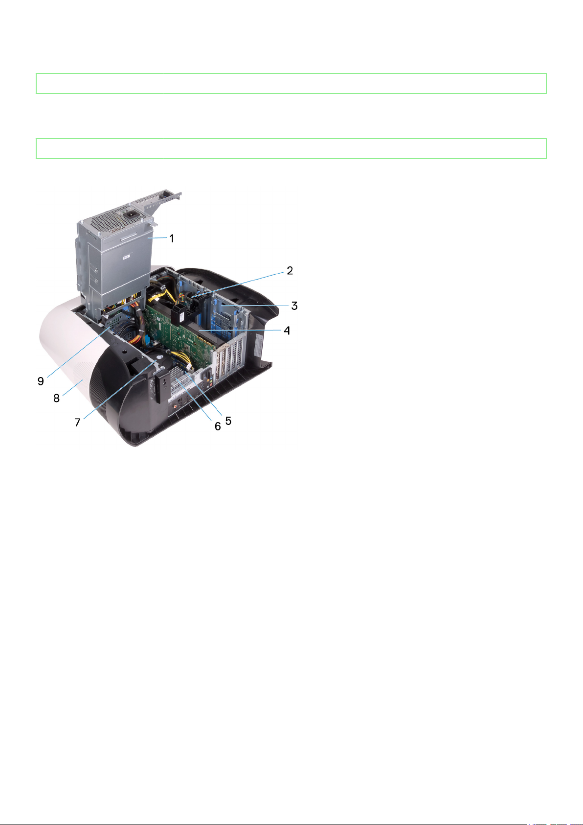
Inside view of your computer
1. power-supply unit
2. 2.5-inch hard drive
3. 2.5-inch hard-drive cage
4. graphics card
5. system board
6. VR heat sink
7. processor fan and liquid cooling assembly
8. top cover
9. 3.5-inch hard-drive cage
9
Page 10
Identifier GUID-238DE792-1E85-4294-891F-EC985C8470AB
Status Released
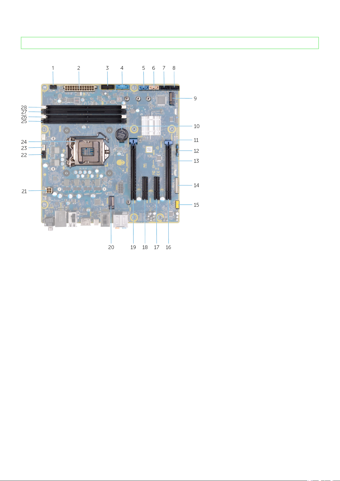
System-board components
1.
front-chassis fan connector (FRONT_FAN)
2. power-supply connector
3. front-panel USB cable 2 (F_USB2)
4. front-panel USB cable 1 (F_USB1)
5. SATA 6 Gbps drive connector (SATA1)
6. SATA 6 Gbps drive connector (SATA2)
7. SATA 6 Gbps drive connector (SATA3)
8. SATA 6 Gbps drive connector (SATA4)
9. solid-state drive slot (M.2 SSD)
10. coin-cell battery
11. Service mode (SERVICE MODE)
12. CMOS reset jumper (CMOS_CLR)
13. Password reset jumper (PW_CLR)
14. LED controller connector (LED_CONTROLLER)
15. front audio connector (F_AUDIO)
16. PCI-Express x8 slot (SLOT4)
17. PCI-Express x4 slot (SLOT3)
18. PCI-Express x4 slot (SLOT3)
19. PCI-Express x16 mechanical/x8 electrical slot (SLOT1)
20. wireless-card slot (M.2 WIFI)
21. processor connector (AIX_CPU)
22. top-chassis fan (TOP_FAN)
23. processor-cooling assembly pump-fan connector (PUMP_FAN)
24. processor socket (CPU1)
25. memory-module slot 3 (DDR4/XMM3)
26. memory-module slot 1 (DDR4/XMM1)
10
Page 11
27. memory-module slot 2 (DDR4/XMM2)
28. memory-module slot 4 (DDR4/XMM4)
Identifier GUID-EA979CC8-84EC-4827-86C4-C80A8C31F4BF
Status Released
Recommended tools
The procedures in this document may require the following tools:
• Philips screwdriver #1
• Flat-head screwdriver
• Plastic scribe
Identifier GUID-CC648B28-FBF9-4A6F-BB11-4C6C2FA3D08A
Status Released
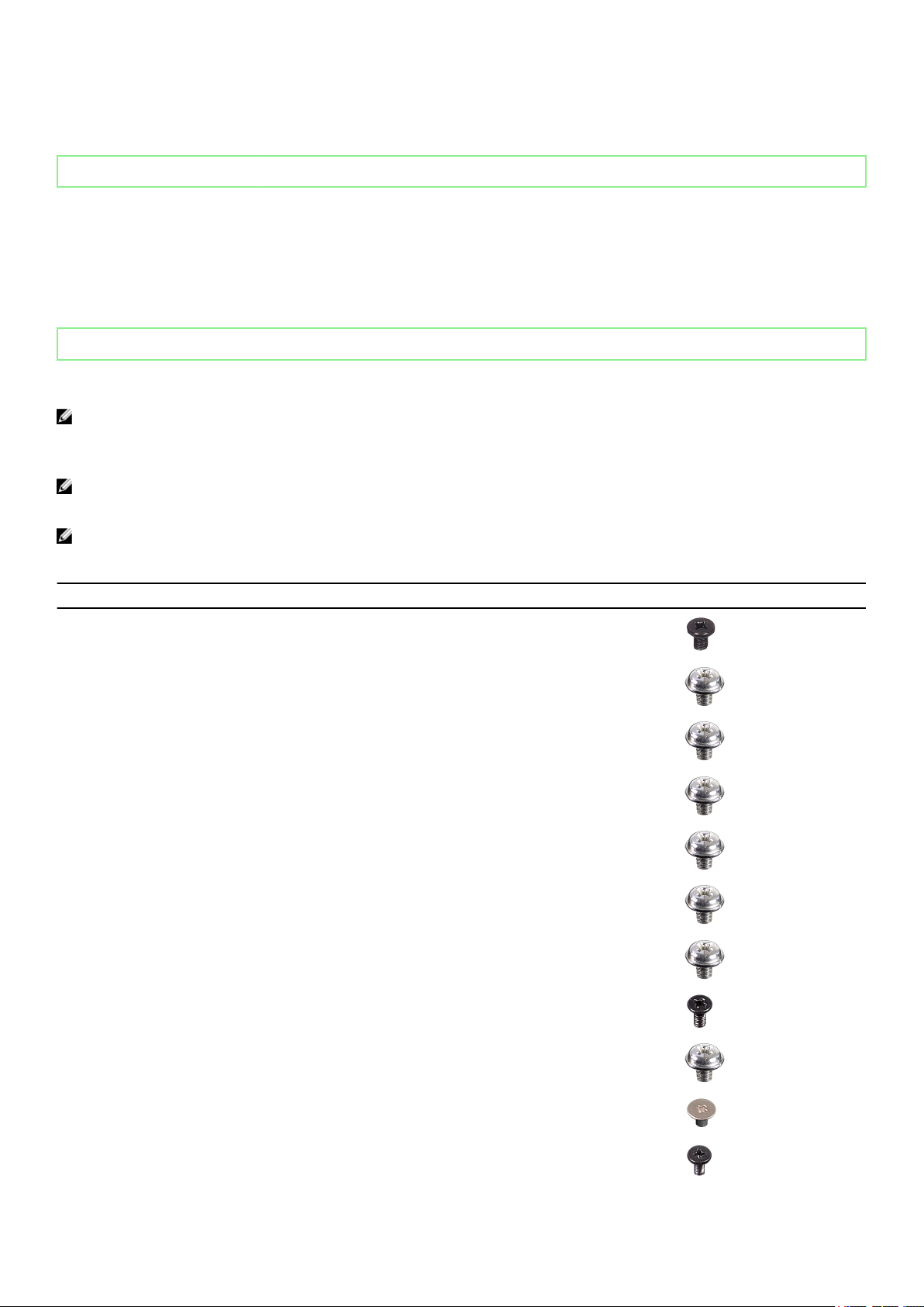
Screw list
NOTE: When removing screws from a component, it is recommended to note the screw type, the quantity of screws,
and then place them in a screw storage box. This is to ensure that the correct number of screws and correct screw
type is restored when the component is replaced.
NOTE: Some computers have magnetic surfaces. Ensure that the screws are not left attached to such surface when
replacing a component.
NOTE: Screw color may vary with the configuration ordered.
Table 1. Screw list
Component Secured to Screw type Quantity Screw image
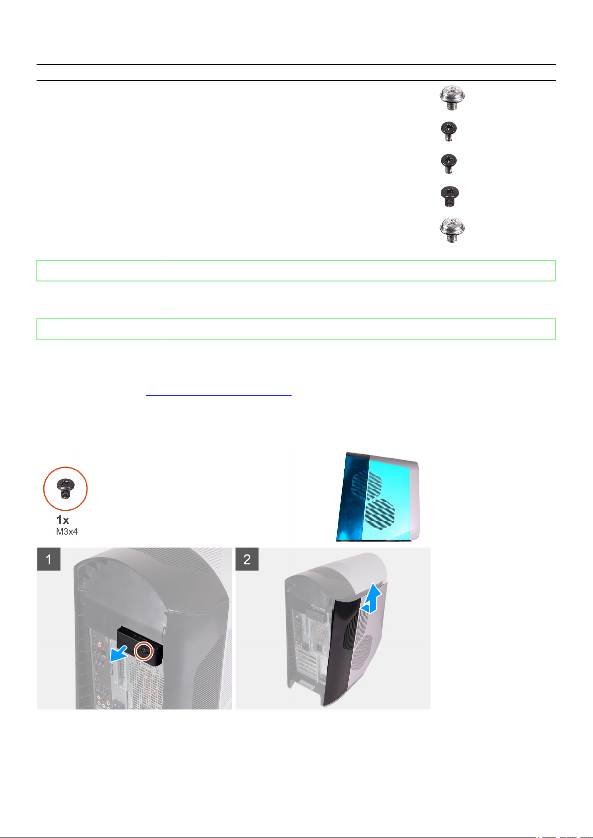
Side-panel release latch Chassis M3x4 1
2.5-inch hard-drive cage Chassis #6-32 2
3.5-inch hard-drive cage Chassis #6-32 2
Power-supply unit
bracket
Power-supply unit Chassis #6-32 4
Right tron-light board Chassis #6-32 4
Radiator and fan
assembly
Antennas Chassis M3x4t 4
Power-supply unit cage #6-32 2
Radiator and fan cage #6-32 4
Top bezel Chassis #6-32 4
Solid-state drive System board M2x2.5 1
Wireless card System board M2x4 1
11
Page 12
Component Secured to Screw type Quantity Screw image
Cable-management
panel
Front-panel light-board Front bezel M2x4 4
Power button module Front bezel M2x4 2
Front I/O-panel Front bezel M3x4 4
System board Chassis #6-32 8
Identifier GUID-E9D0D744-F098-486A-9576-4EEEC69CDCD7
Status Released
Chassis #6-32 2
Left-side cover
Identifier GUID-A97423F0-680A-4496-9FFC-1425A29616EC
Status Released
Removing the left-side cover
Prerequisites
1. Follow the procedure in Before working inside your computer.
About this task
The following images indicate the location of the left-side cover and provides a visual representation of the removal procedure.
Steps
1. Remove the screw (M3x4) that secures the side-cover release latch to the chassis.
12
Page 13
2. Pull the side-cover release latch to release the left-side cover away from the chassis.
3. Lift the left-side panel from the chassis.
Identifier GUID-508E90CB-F339-4BD8-A469-D02039D5FEA7
Status Released
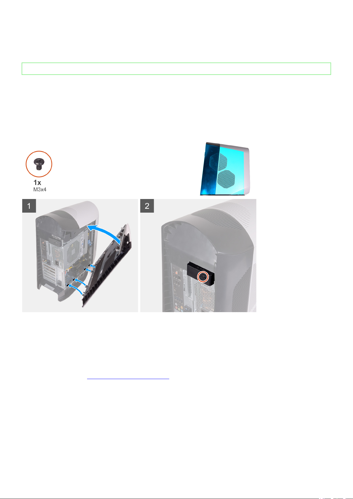
Installing the left-side cover
Prerequisites
If you are replacing a component, remove the existing component before performing the installation procedure.
About this task
The following images indicate the location of the left-side cover and provides a visual representation of the installation procedure.
Steps
1. Locate the tabs on the left-side cover and slots on the chassis.
2. Rotate the left-side cover towards the chassis until it snaps into place.
3. Replace the screw (M3x4) that secures the side-cover release latch to the chassis.
Next steps
1. Follow the procedure in After working inside your computer.
13
Page 14
Identifier GUID-620085B3-6141-4F38-9D7B-9D41454DBC1B
Status Released
Top cover
Identifier GUID-24AF8F06-18F7-404C-BA7A-1F814D07C178
Status Released
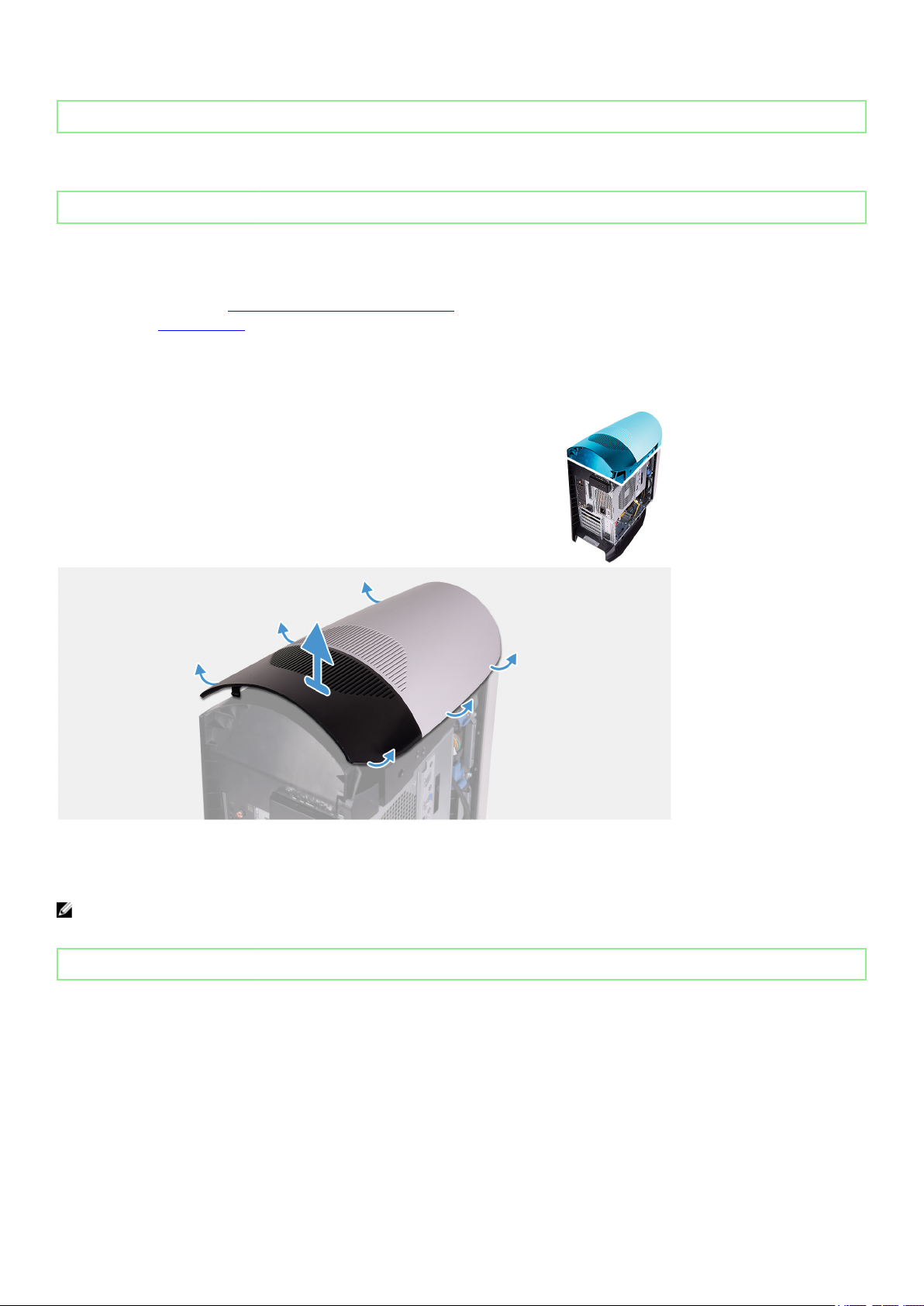
Removing the top cover
Prerequisites
1. Follow the procedure in Before working inside your computer.
2. Remove the left-side cover.
About this task
The following images indicate the location of the top cover and provides a visual representation of the removal procedure.
Steps
Starting from the rear, pull up on the top cover to release it from the chassis.
NOTE: Top cover is tightly secured to the chassis by clips and may requires force to remove it off the chassis.
Identifier GUID-405B7B75-37D2-4E7D-B423-5A31753387B6
Status Released
Installing the top cover
Prerequisites
If you are replacing a component, remove the existing component before performing the installation procedure.
About this task
The following images indicate the location of the top cover and provides a visual representation of the installation procedure.
14
Page 15
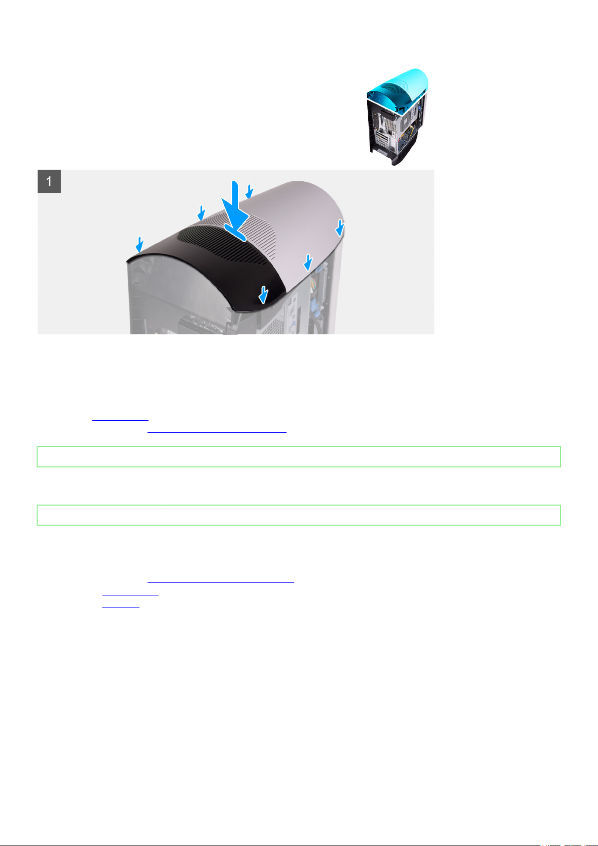
Steps
Align the tabs on the top cover with the slots on the chassis and snap the top cover into place.
Next steps
1. Install the left-side cover.
2. Follow the procedure in After working inside your computer.
Identifier
Status Released
GUID-47CC4B39-1E69-4DF9-AAA6-115CC8553BCC
Right-side cover
Identifier
Status Released
Removing the right-side cover
Prerequisites
1. Follow the procedure in Before working inside your computer.
2. Remove the left-side cover.
3. Remove the top cover.
About this task
The following images indicate the location of the right-side cover and provides a visual representation of the removal procedure.
GUID-853210C9-D31A-424A-B01F-E14CB7936497
15
Page 16
Steps
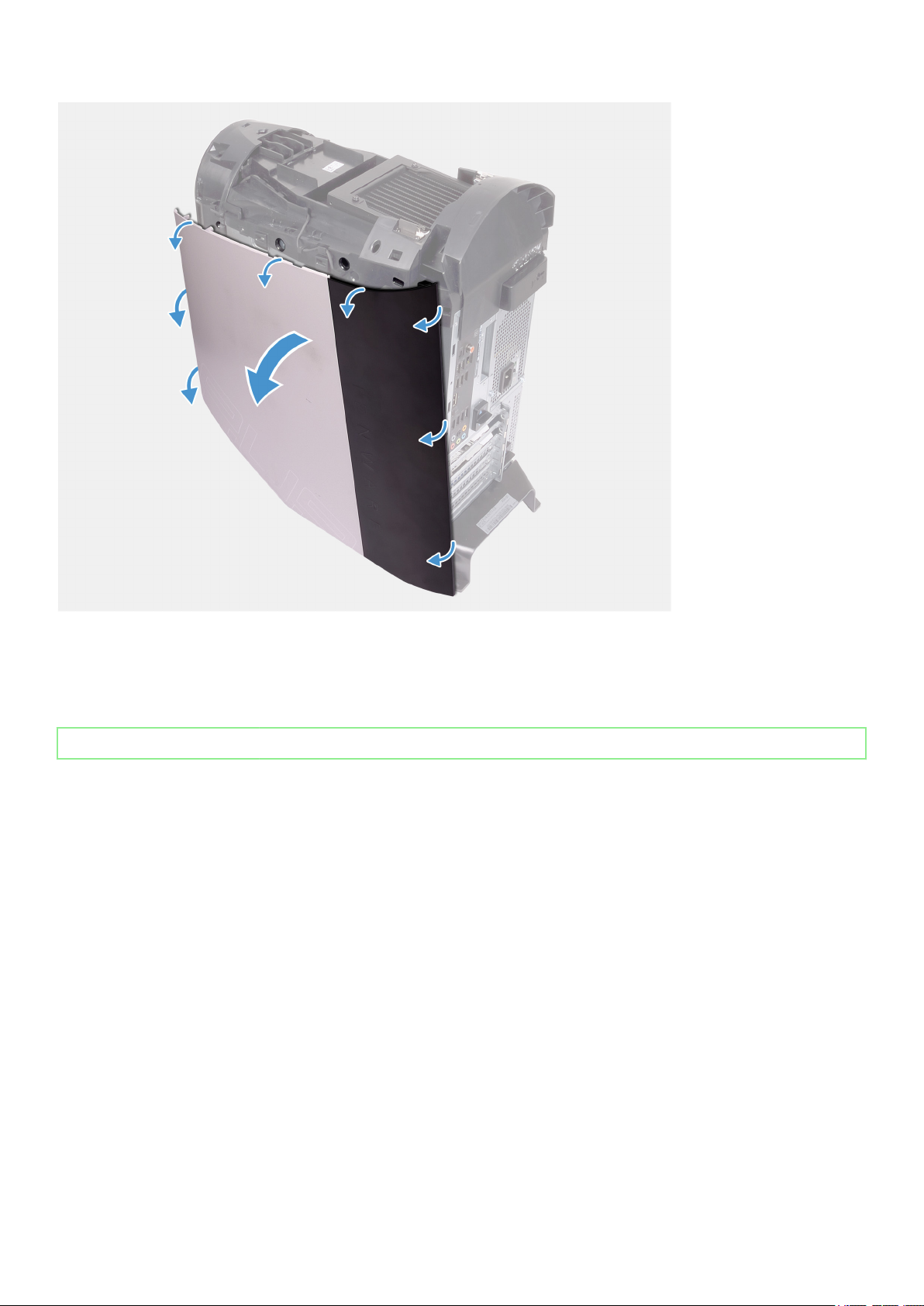
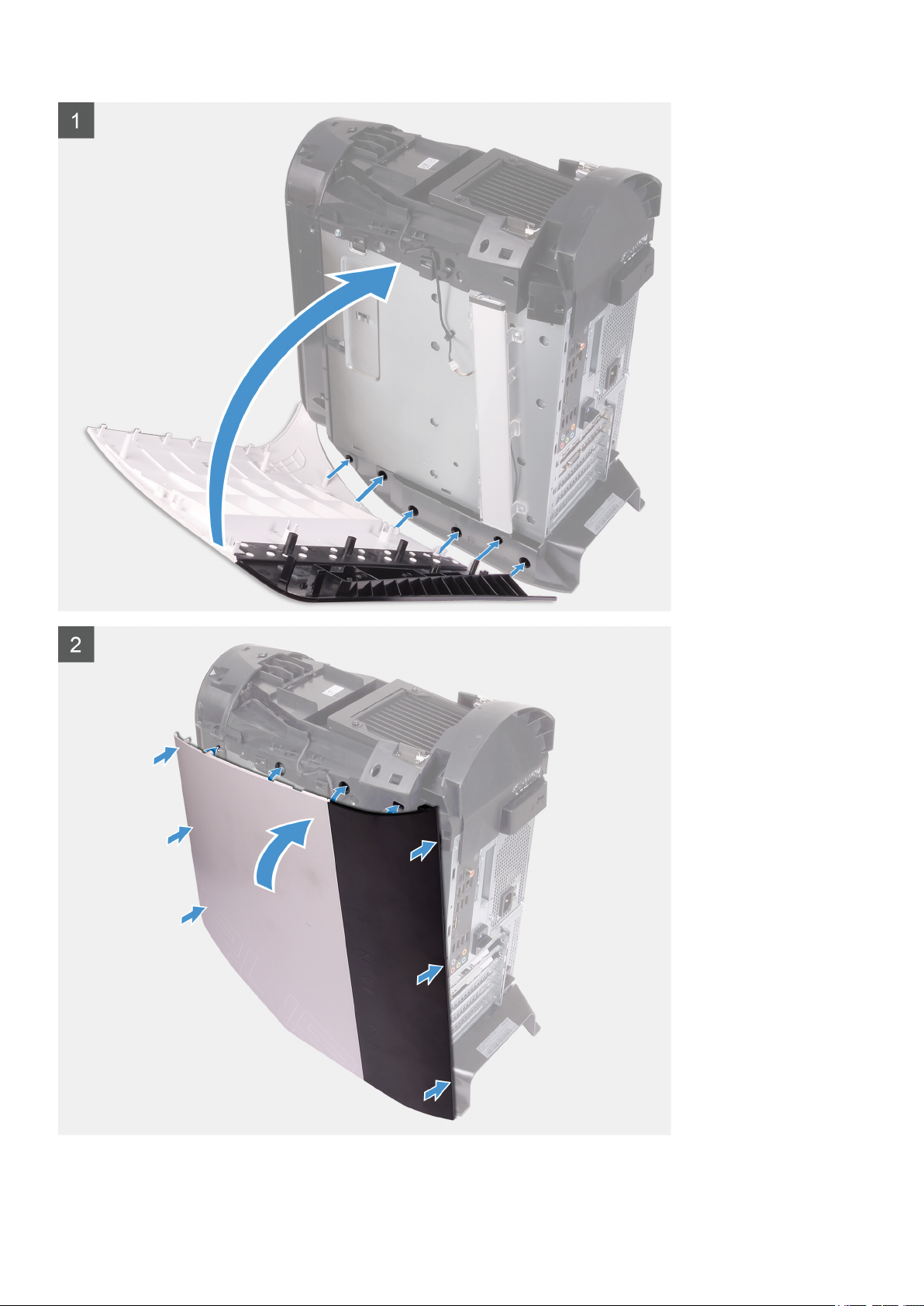
1. Starting from the top-front tab, pull the right-side cover away from the chassis.
2. Remove the right-side cover from the chassis.
Identifier
Status Released
GUID-B108C3E6-8802-4D81-82D1-696C73C5AB41
Installing the right-side cover
Prerequisites
If you are replacing a component, remove the existing component before performing the installation procedure.
About this task
The following images indicate the location of the right-side cover and provides a visual representation of the installation procedure.
16
Page 17
17
Page 18

Steps
1. Align the tabs on the right-side cover with the slots on the chassis
2. Rotate the right-side cover towards the chassis until it snaps into place.
Next steps
1. Install the top cover.
2. Install the left-side cover.
3. Follow the procedure in After working inside your computer.
Identifier GUID-48E04E13-AE09-46CA-9395-A522584DB9B8
Status Released
2.5-inch hard drive
Identifier GUID-6B215E2D-4EA8-4234-9347-68EB28774771
Status Released
Removing the 2.5-inch hard drive
Prerequisites
1. Follow the procedure in Before working inside your computer.
2. Remove the left-side cover.
About this task
The following images indicate the location of the 2.5-inch hard drive and provides a visual representation of the removal procedure.
18
Page 19
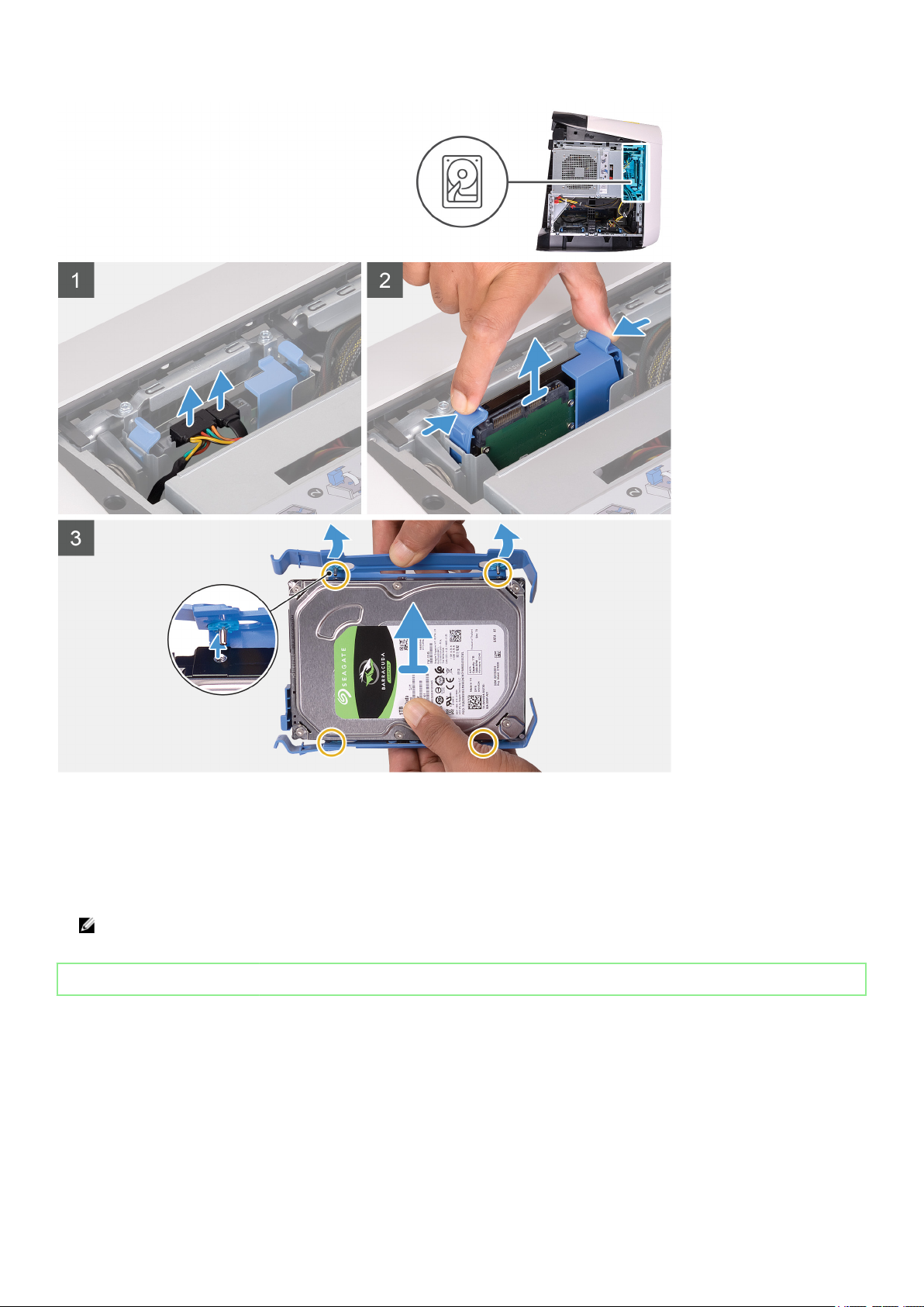
Steps
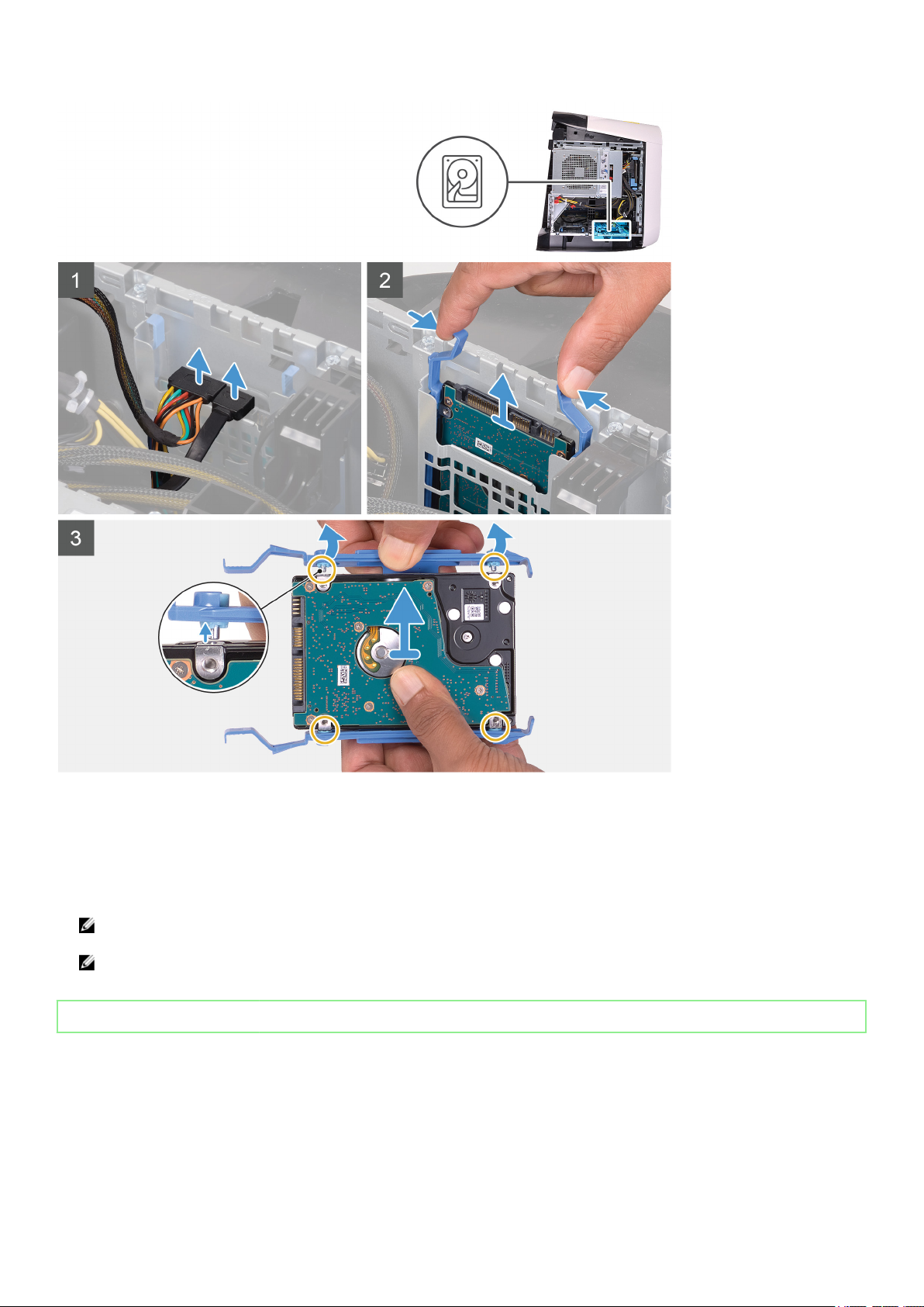
1. Disconnect the data and power cables from the hard drive.
2. Press the release tabs on the hard-drive carrier and slide the hard-drive assembly out of the hard-drive cage.
3. Pry the hard-drive carrier to release the tabs on the assembly from the slots on the hard drive.
4. Lift the hard drive out of the hard-drive assembly.
NOTE: Note the orientation of the hard drive so that you can replace it correctly.
NOTE: Repeat the steps to remove any additional 2.5-inch hard drive from your computer.
Identifier GUID-275897FB-5590-421A-BCB2-21150A688A6D
Status Released
Installing the 2.5-inch hard drive
Prerequisites
If you are replacing a component, remove the existing component before performing the installation procedure.
19
Page 20
About this task
The following images indicate the location of the 2.5-inch hard drive and provides a visual representation of the installation
procedure.
20
Page 21

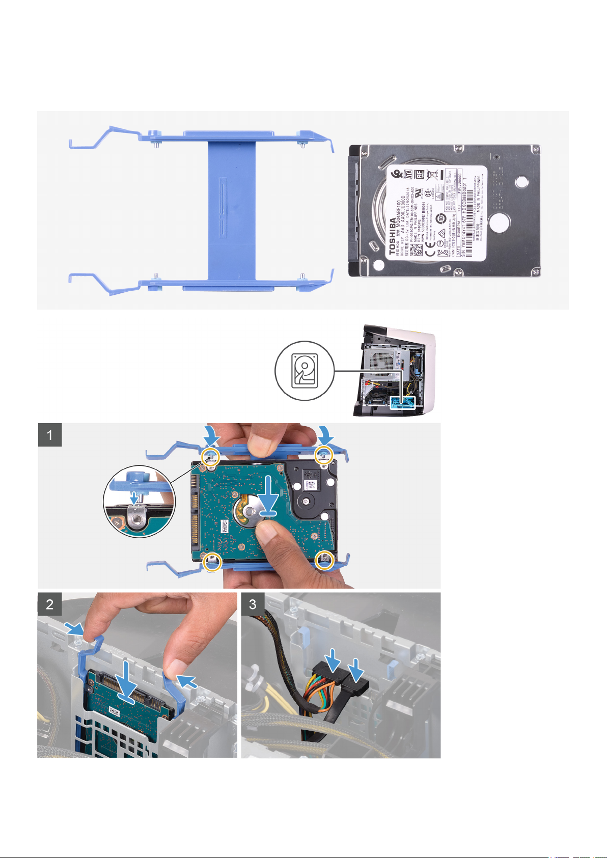
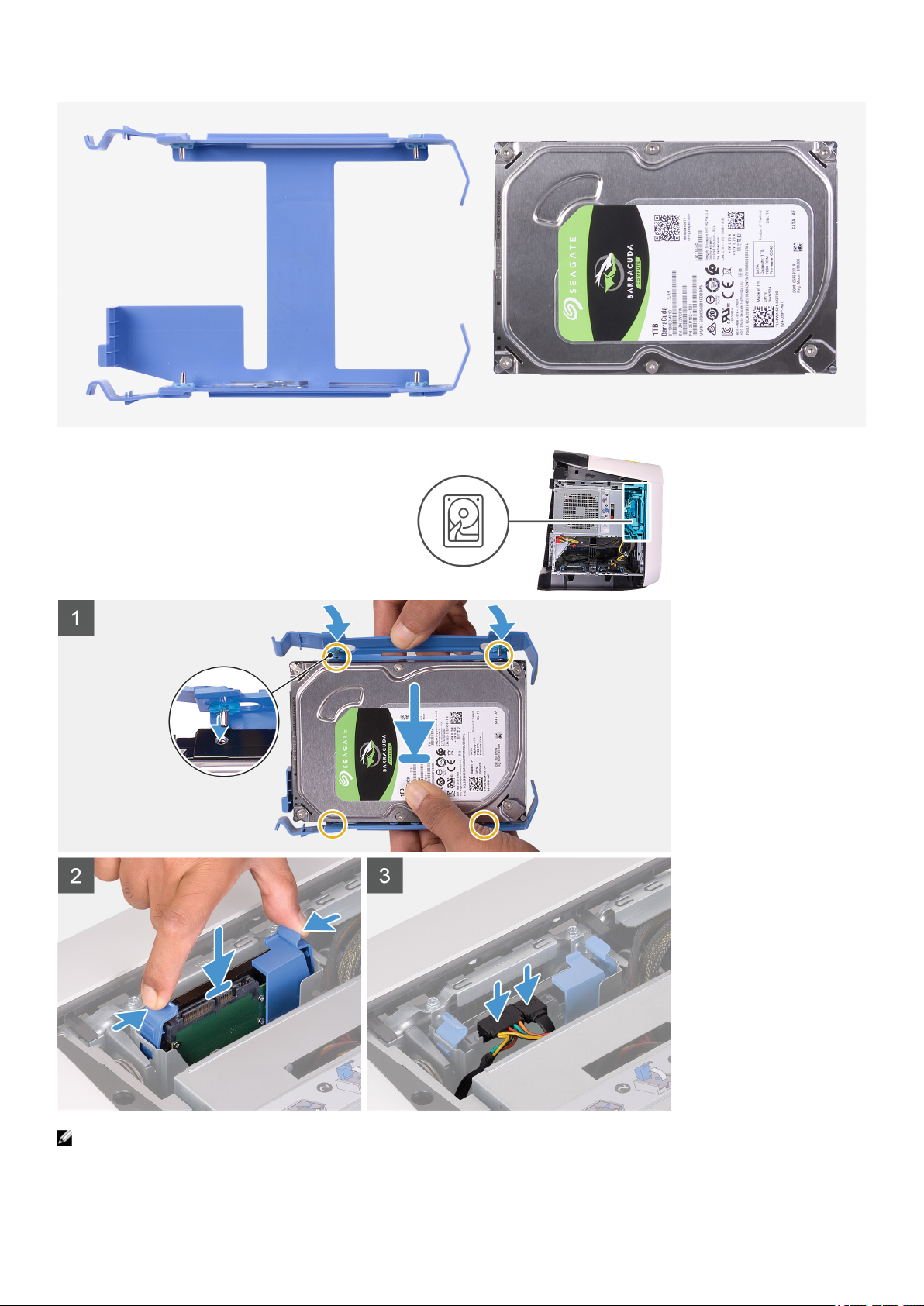
NOTE: Note the orientation on the hard-drive carrier to replace it correctly.
Steps
1. Align the hard drive with the pins on the hard-drive carrier.
2. Using the tabs on the opposite side, flex open the carrier to insert the pins on the other side.
3. Slide the hard-drive assembly into the hard-drive cage until it snaps into place.
4. Connect the data cable and power cable to the hard drive.
NOTE: Repeat the steps to install any additional 2.5-inch hard drive from your computer.
Next steps
1. Install the left-side cover.
2. Follow the procedure in After working inside your computer.
Identifier GUID-DFA3DF29-7400-460D-B0A6-B30544A46E4A
Status Released
3.5-inch hard drive
Identifier GUID-D9C16C7A-A854-4337-A7DD-A72CA49185FF
Status Released
Removing the 3.5-inch hard drive
Prerequisites
1. Follow the procedure in Before working inside your computer.
2. Remove the left-side cover.
About this task
The following images indicate the location of the 3.5-inch hard drive and provides a visual representation of the removal procedure.
21
Page 22
Steps
1. Disconnect the data and power cables from the hard drive.
2. Press the release tabs on the hard-drive carrier and slide the hard-drive carrier out of the hard-drive cage.
3. Pry the hard-drive carrier to release the tabs on the carrier from the slots on the hard drive.
4. Lift the hard drive out of the hard-drive assembly.
NOTE: Note the orientation of the hard drive so that you can replace it correctly.
Identifier GUID-F07172A4-38E4-4597-9B16-1AAA90FD55D0
Status Released
Installing the 3.5-inch hard drive
Prerequisites
If you are replacing a component, remove the existing component before performing the installation procedure.
About this task
The following images indicate the location of the 3.5-inch hard drive and provides a visual representation of the installation
procedure.
22
Page 23
NOTE: Note the orientation on the hard-drive carrier to replace it correctly.
23
Page 24
Steps
1. Align the hard drive with the pins on the hard-drive carrier.
2. Using the tabs on the opposite side, flex open the carrier to insert the pins on the other side.
3. Slide the hard-drive assembly into the hard-drive cage until it snaps into place.
4. Connect the data and power cables to the hard drive.
Next steps
1. Install the left-side cover.
2. Follow the procedure in After working inside your computer.
Identifier GUID-D81D7691-6844-4C8C-9674-BE582EB058F8
Status Released
2.5-inch hard-drive cage
Identifier GUID-0735C260-B509-46C6-84D8-1F3463519C27
Status Released
Removing the 2.5-inch hard-drive cage
Prerequisites
1. Follow the procedure in Before working inside your computer.
2. Remove the left-side cover.
3. Remove the 2.5-inch hard drive, if installed.
About this task
The following images indicate the location of the 2.5-inch and provides a visual representation of the removal procedure.
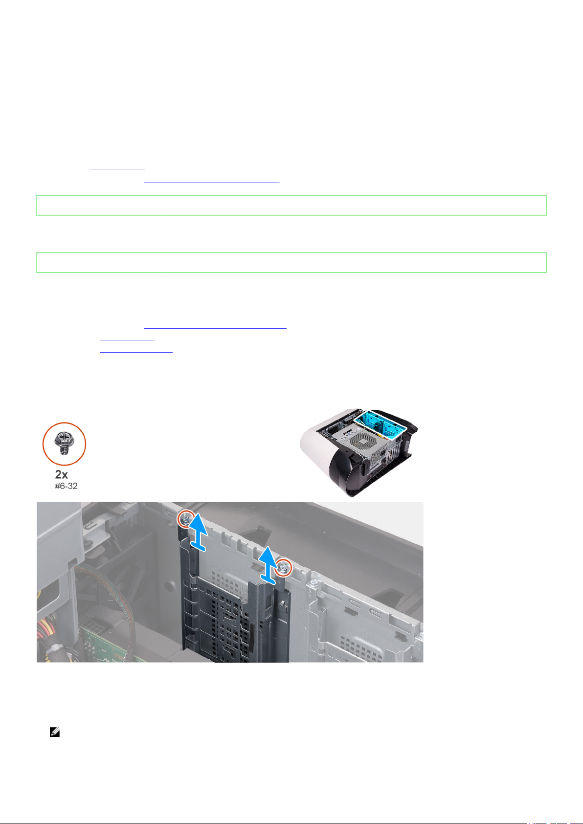
Steps
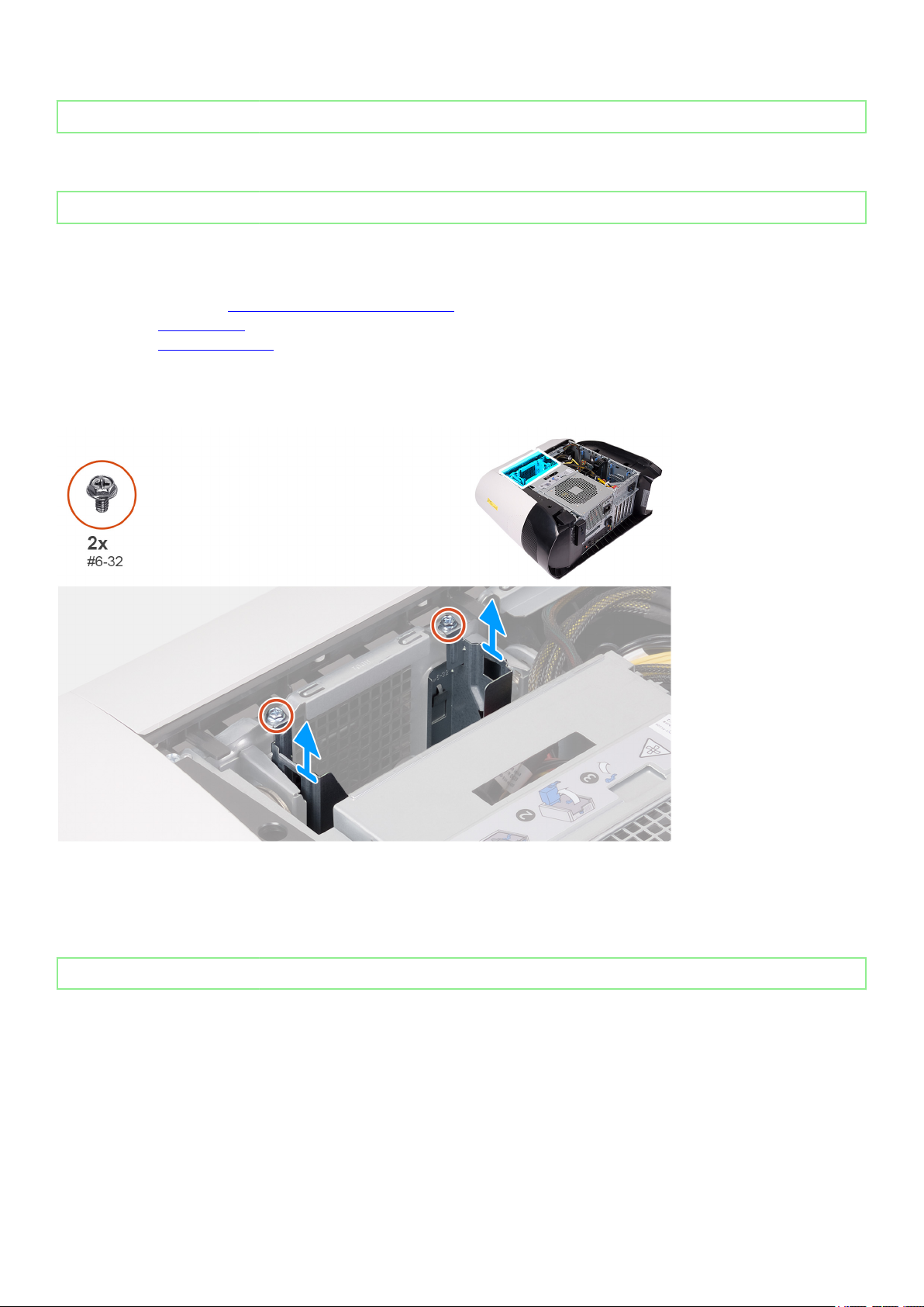
1. Remove the two screws (#6-32) that secure the 2.5-inch hard-drive cage to the chassis.
2. Slide and remove the 2.5-inch hard-drive cage off the chassis.
NOTE: Repeat the procedure from step 1 to step 2 to remove the other 2.5-inch hard-drive cage.
24
Page 25
Identifier GUID-8E2AAFD1-CFB8-44DD-AAC7-D3125BB9A58E
Status Released
Installing the 2.5-inch hard-drive cage
Prerequisites
If you are replacing a component, remove the existing component before performing the installation procedure.
About this task
The following images indicate the location of the 2.5-inch hard-drive cage and provides a visual representation of the installation
procedure.
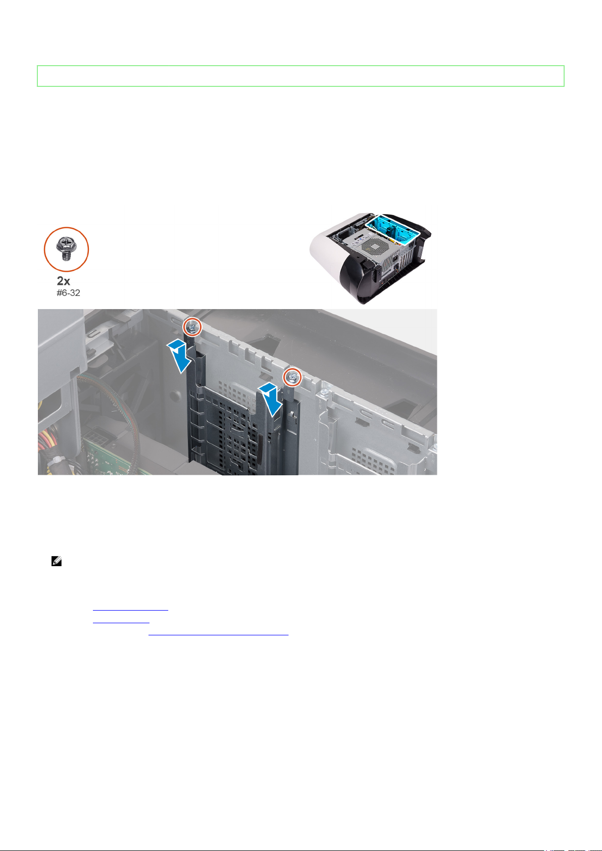
Steps
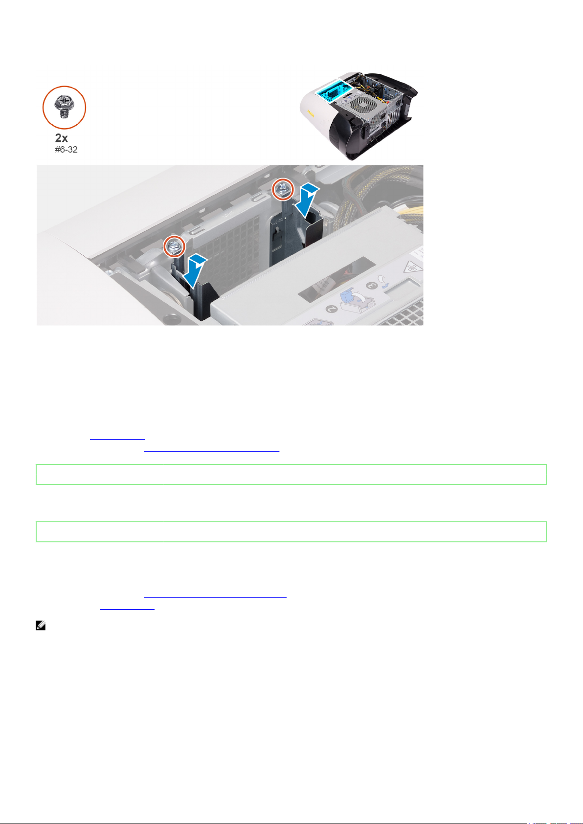
1. Insert the 2.5-inch hard-drive cage into its slot on the chassis.
2. Align the tabs on the cage with the tabs on the chassis.
3. Replace the two screws (#6-32) that secure the 2.5-inch hard-drive cage to the chassis.
NOTE: Repeat the procedure from step 1 to step 3 to install the other 2.5-inch hard-drive cage.
Next steps
1. Install the 2.5-inch hard drive, if required.
2. Install the left-side cover.
3. Follow the procedure in After working inside your computer.
25
Page 26
Identifier GUID-44EEE532-23C0-44F6-BD38-36469E5FFD8D
Status Released
3.5-inch hard-drive cage
Identifier GUID-E5668432-AA17-4F4E-A3E5-A97A0FAD0BEA
Status Released
Removing the 3.5-inch hard-drive cage
Prerequisites
1. Follow the procedure in Before working inside your computer.
2. Remove the left-side cover.
3. Remove the 3.5-inch hard drive, if installed.
About this task
The following images indicate the location of the 3.5-inch and provides a visual representation of the removal procedure.
Steps
1. Remove the two screws (#6-32) that secure the 3.5-inch hard-drive cage to the chassis.
2. Lift the 3.5-inch hard-drive cage off the chassis.
Identifier
Status Released
GUID-0852762D-895D-4086-8E33-B73077AEEA10
Installing the 3.5-inch hard-drive cage
Prerequisites
If you are replacing a component, remove the existing component before performing the installation procedure.
About this task
The following images indicate the location of the 3.5-inch hard-drive cage and provides a visual representation of the installation
procedure.
26
Page 27
Steps
1. Insert the 3.5-inch hard-drive cage into its slot on the chassis.
2. Align the tabs on the cage with the tabs on the chassis.
3. Replace the two screws (#6-32) that secure the 3.5-inch hard-drive cage to the chassis.
Next steps
1. Install the left-side cover.
2. Follow the procedure in After working inside your computer.
Identifier
Status Released
GUID-88726DE4-DA39-4C4B-8EF5-3DD564906BEA
460 W power-supply unit
Identifier
Status Released
Removing the 460 W power-supply unit
Prerequisites
1. Follow the procedure in Before working inside your computer.
2. Remove the left-side cover.
NOTE: Note the routing of all cables as you remove them so that you can route them correctly after you replace the
power-supply unit.
About this task
The following images indicate the location of the power-supply unit and provides a visual representation of the removal procedure.
GUID-4957DE0C-A6C3-4AF0-89EB-EDC1F5734446
27
Page 28
28
Page 29
Steps
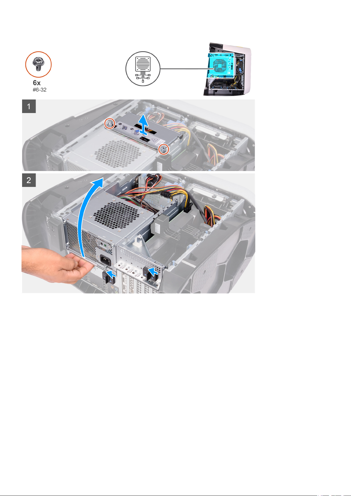
1. Remove the two screws (#6-32) that secure the power-supply unit bracket to the power-supply unit cage.
2. Lift the power-supply unit bracket off the power-supply unit cage.
3. Lift the power-supply unit cage and rotate the power-supply unit cage away from the chassis.
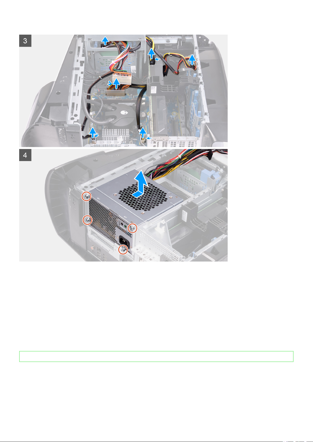
4. Press the releasing clip on the power-cable connectors and disconnect the power cables from the graphics card.
5. Disconnect the power cables from the hard drives.
6. Disconnect the processor-power cable and system-board power cable from the system board.
7. Rotate the power-supply unit cage towards the chassis.
8. Remove the four screws (#6-32) that secure the power-supply unit to the chassis.
9. Slide and lift the power-supply unit, along with the cables, off the chassis.
Identifier
Status Released
GUID-53CB7106-AC83-4281-84FF-08B8BD9CEBA9
Installing the 460 W power-supply unit
Prerequisites
If you are replacing a component, remove the existing component before performing the installation procedure.
29
Page 30
WARNING: The cables and ports on the back of the power-supply unit are color-coded to indicate the different power
wattage. Ensure that you plug in the cable to the correct port. Failure to do so may result in damaging the powersupply unit and/or system components.
About this task
The following images indicate the location of the power-supply unit and provides a visual representation of the installation
procedure.
30
Page 31

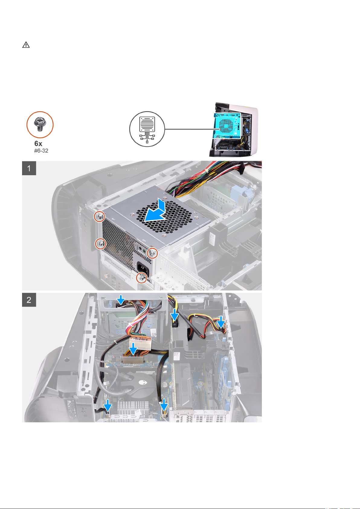
Steps
1. Place the power supply on the chassis.
2. Align the screw holes on the power-supply unit with the screw holes on the chassis.
3. Replace the four screws (#6-32) that secure the power-supply unit to the chassis.
4. Lift and rotate the power-supply unit cage away from the chassis
5. Connect the processor-power cable and system-board power cable to the system board.
6. Connect the power cables to the hard drives.
7. Connect the power cables to the graphics card.
8. Rotate the power-supply unit cage towards the chassis
9. Slide the power-supply unit cage release latches towards the locked position.
10. Align the screw holes on the power-supply unit bracket with the screw holes on the power-supply unit cage.
11. Replace the two screws (#6-32) that secure the power-supply unit bracket to the power-supply unit cage.
Next steps
1. Install the left-side cover.
2. Follow the procedure in After working inside your computer.
31
Page 32

Identifier GUID-503E968B-8693-464C-BD25-B3690D37D365
Status Released
850 W Power-supply unit
Identifier GUID-86608D10-D747-4DDD-82E7-B43EF6F92854
Status Released
Removing the 850 W power-supply unit
Prerequisites
1. Follow the procedure in Before working inside your computer.
2. Remove the left-side cover.
NOTE: Note the routing of all cables as you remove them so that you can route them correctly after you replace the
power-supply unit.
About this task
The following images indicate the location of the power-supply unit and provides a visual representation of the removal procedure.
32
Page 33

Steps
1. Remove the two screws (#6-32) that secure the power-supply unit bracket to the power-supply unit cage.
2. Lift the power-supply unit bracket off the power-supply unit cage.
3. Press the releasing clip on the power-cable connectors and disconnect all the power cables from the power-supply unit.
4. Remove the four screws (#6-32) that secure the power-supply unit to the chassis.
5. Slide and lift the power-supply unit, along with the cables, off the chassis.
Identifier GUID-5452F553-ECCE-4406-9479-98B9804A425B
Status Released
Installing the 850 W power-supply unit
Prerequisites
If you are replacing a component, remove the existing component before performing the installation procedure.
WARNING: The cables and ports on the back of the power-supply unit are color-coded to indicate the different power
wattage. Ensure that you plug in the cable to the correct port. Failure to do so may result in damaging the powersupply unit and/or system components.
About this task
The following images indicate the location of the power-supply unit and provides a visual representation of the installation
procedure.
33
Page 34

Steps
1. Place the power supply on the chassis.
2. Align the screw holes on the power-supply unit with the screw holes on the chassis.
3. Replace the four screws (#6-32) that secure the power-supply unit to the chassis.
4. Connect all the power cables to the power-supply unit.
5. Align the screw holes on the power-supply unit bracket with the screw holes on the power-supply unit cage.
6. Replace the two screws (#6-32) that secure the power-supply unit bracket to the power-supply unit cage.
Next steps
1. Install the left-side cover.
2. Follow the procedure in After working inside your computer.
34
Page 35

Identifier GUID-A2B01E9B-CEE6-4E67-BCE0-93A927E80764
Status Released
Right tron-light board
Identifier GUID-EB56B368-61E6-46BB-B405-C08BD26A0FCC
Status Released
Removing the right tron-light board
Prerequisites
1. Follow the procedure in Before working inside your computer.
2. Remove the left-side cover.
3. Remove the top-cover.
4. Remove the right-side cover.
About this task
The following images indicate the location of the right tron-light board and provides a visual representation of the removal
procedure.
35
Page 36

Steps
1. Disconnect the tron-light cable.
2. Remove the four screws (#6-32) that secure the right tron-light board to the chassis.
3. Remove the right tron-light board off the chassis.
Identifier GUID-7234299B-186B-4AE5-90DA-A4F67B6666CF
Status Released
Installing the right tron-light board
Prerequisites
If you are replacing a component, remove the existing component before performing the installation procedure.
About this task
The following images indicate the location of the right tron-light board and provides a visual representation of the installation
procedure.
Steps
1. Align the screw holes on the right tron-light board with the screw holes on the chassis.
2. Replace the four screws (#6-32) that secure the right tron-light board to the chassis.
36
Page 37

3. Connect the tron-light cable.
Next steps
1. Install the right-side cover.
2. Install the top-cover.
3. Install the left-side cover.
4. Follow the procedure in After working inside your computer.
Identifier GUID-7E776F1F-1FBF-4B34-AD17-18E98DB265CE
Status Released
Processor liquid-cooling assembly
Identifier GUID-12547E7D-5948-4AA2-B0DA-F9049C082CEB
Status Released
Removing the processor liquid-cooling assembly
Prerequisites
1. Follow the procedure in Before working inside your computer.
WARNING: Despite having a plastic shield, the processor liquid-cooling assembly may be very hot during normal
operation. Ensure that it had sufficient time to cool before you touch it.
CAUTION: To ensure maximum cooling for the processor, do not touch the heat transfer areas on the processor
liquid-cooling assembly. The oils in your skin can reduce the heat transfer capability of the thermal grease.
2. Remove the left-side cover.
3. Remove the top-cover.
4. Remove the right-side cover.
5. Remove the memory modules.
About this task
The following images indicate the location of the processor liquid-cooling assembly and provides a visual representation of the
removal procedure.
37
Page 38

38
Page 39

Steps
1. Lay the computer on the right side.
2. Slide the power-supply unit cage release latches to the unlock position.
3. Lift the power-supply unit cage.
4. Rotate the power-supply unit cage away from the chassis.
5. Loosen the two captive screws that secure the VR heat sink to the system board.
6. Remove the four screws (#6-32) that secure the radiator and fan assembly to the radiator and fan cage.
7. Lift the VR heat sink off the computer.
8. Disconnect the processor-cooling assembly cables from the system board.
9. In the reverse sequential order (as indicated on the processor cooler), loosen the four captive screws that secure the processor
cooler to the system board.
NOTE: If your are using an electric screwdriver, torque the screws at 6.9 +/-1.15 kilogram-force centimeter (6 +/-1
pound force inch).
10. Lift the processor-cooling assembly along with the cables off the computer.
39
Page 40

Identifier GUID-F0C8F9A0-A9BB-4E1D-8720-B669A9CC1F0F
Status Released
Installing the processor liquid-cooling assembly
Prerequisites
If you are replacing a component, remove the existing component before performing the installation procedure.
CAUTION: Incorrect alignment of the processor liquid-cooling assembly can damage the system board and
processor.
About this task
The following images indicate the location of the processor liquid-cooling assembly and provides a visual representation of the
installation procedure.
40
Page 41

Steps
1. Slide the radiator and fan assembly into the radiator and fan cage.
NOTE: Ensure that the hoses are facing the front of the system
2. Align the screw holes on the processor cooler with the screw holes on the system board.
3. Align the screw holes on the VR heat sink with the screw holes on the system board.
4. Tighten the two captive screws that secure the VR heat sink to the system board.
5. In the sequential order (as indicated on the processor cooler), tighten the four captive screws that secure the processor cooler
to the system board.
NOTE: If your are using an electric screwdriver, torque the screws at 6.9 +/-1.15 kilogram-force centimeter (6 +/-1
pound force inch).
6. Connect the processor-cooling assembly cables to the system board.
7. Replace the four screws (#6-32) that secure the radiator and fan assembly to the chassis.
8. Rotate the power-supply unit cage towards the chassis.
9. Slide the power-supply unit cage release latches towards the locked position.
Next steps
1. Install the memory modules.
2. Install the right-side cover.
3. Install the top-cover.
4. Install the left-side cover.
5. Follow the procedure in After working inside your computer.
41
Page 42

Identifier GUID-D99D5F9B-0FF3-406B-A51F-FFA061BB89EA
Status Released
Coin-cell battery
Identifier GUID-2CD64C9B-AC2C-4313-B17E-BCB5C2900231
Status Released
Removing the coin-cell battery
Prerequisites
1. Follow the procedure in Before working inside your computer.
NOTE: Before working inside your computer, read the safety information that shipped with your computer and
follow the steps in Before working inside your computer. After working inside your computer, follow the
instructions in After working inside your computer. For more safety best practices, see the Regulatory
Compliance home page at www.dell.com/regulatory_compliance.
CAUTION: Removing the coin-cell battery resets the BIOS setup program’s settings to default. It is recommended
that you note the BIOS setup program’s settings before removing the coin-cell battery.
2. Remove the left-side cover.
About this task
The following images indicate the location of the coin-cell battery and provides a visual representation of the removal procedure.
42
Page 43

Steps
1. Lay the computer on the right side.
2. Slide the power-supply unit cage release latches to the unlock position.
3. Lift the power-supply unit cage and rotate the power-supply unit cage away from the chassis.
4. Press the battery-release lever away from the coin-cell battery until the coin-cell battery pops up.
5. Lift the coin-cell battery out of its socket.
Identifier
Status Released
GUID-695AF3FB-15C6-4A26-A28E-F296FD2A221C
Installing the coin-cell battery
Prerequisites
If you are replacing a component, remove the existing component before performing the installation procedure.
About this task
The following images indicate the location of the coin-cell battery and provides a visual representation of the installation procedure.
43
Page 44

Steps
1. Insert a new coin-cell battery (CR2032) into the battery socket with the positive side facing up, and snap the battery into place.
44
Page 45

2. Rotate the power-supply unit cage towards the chassis.
3. Slide the power-supply unit cage release latches towards the locked position.
Next steps
1. Install the left-side cover.
2. Follow the procedure in After working inside your computer.
Identifier GUID-2A6DAE1B-1FBE-40F9-8D46-40E8C3FBD267
Status Released
Memory modules
Identifier GUID-590C016E-BA8E-42F6-A918-4851C3BD3713
Status Released
Removing the memory modules
Prerequisites
1. Follow the procedure in Before working inside your computer.
2. Remove the left-side cover.
About this task
The following images indicate the location of the memory modules and provides a visual representation of the removal procedure.
45
Page 46

Steps
1. Lay the computer on the right side.
2. Slide the power-supply unit cage release latches to the unlock position.
3. Lift the power-supply unit cage and rotate the power-supply unit cage away from the chassis.
4. Push the securing clips away from the memory module.
5. Grasp the memory module near the securing clip, and then gently ease the memory module out of the memory-module slot.
NOTE: Repeat step 5 to step 6 to remove any other memory modules installed in your computer.
CAUTION: To prevent damage to the memory module, hold the memory module by the edges. Do not touch the
components on the memory module.
Identifier GUID-F3FCC2B6-BB4B-41C3-A34C-D4B75B35D62F
Status Released
Installing the memory modules
Prerequisites
If you are replacing a component, remove the existing component before performing the installation procedure.
About this task
The following images indicate the location of the memory modules and provides a visual representation of the installation
procedure.
46
Page 47

Steps
1. Ensure that the securing clips are extended away from the memory-module slot.
47
Page 48

2. Align the notch on the memory module with the tab on the memory-module slot.
3. Insert the memory module into the memory-module slot and press the memory module down until it snaps into position and the
securing clips lock in place.
CAUTION: To prevent damage to the memory module, hold the memory module by the edges. Do not touch the
components on the memory module.
NOTE: Repeat step 1 to step 3 to replace any other memory modules installed in your computer.
4. Rotate the power-supply unit cage towards the chassis.
5. Slide the power-supply unit cage release latches towards the locked position.
NOTE: Use slots XMM1 and XMM2 if you need to use two memory modules. For more information, see System-
board components.
The following table lists the available memory configuration matrix:
Table 2. Memory configuration matrix
Configuration
8 GB DDR4 8 GB
16 GB DDR4 8 GB 8 GB
32 GB DDR4 16 GB 16 GB
64 GB DDR4 16 GB 16 GB 16 GB 16 GB
16 GB XMP 8 GB 8 GB
32 GB XMP 16 GB 16 GB
64 GB XMP 16 GB 16 GB 16 GB 16 GB
Next steps
1. Remove the left-side cover.
2. Follow the procedure in After working inside your computer.
Identifier
Status Released
XMM1 XMM2 XMM3 XMM4
GUID-42A997F5-329D-4712-8018-6C6114C5255F
Slot
Solid-state drive
Identifier
Status Released
Removing the solid-state drive
GUID-2FDD0FF0-61C1-4661-85BF-206FB411F5BA
Prerequisites
1. Follow the procedure in Before working inside your computer.
CAUTION: Solid-state drives are fragile. Exercise care when handling the solid-state drive.
NOTE: To avoid data loss, do not remove the drive while the computer is in sleep or on state.
2. Remove the left-side cover.
3. Remove the single-graphics card or dual-graphics card, as applicable.
About this task
The following images indicate the location of the solid-state drive and provides a visual representation of the removal procedure.
48
Page 49

Steps
1. Remove the screw (M2x2.5) that secures the solid-state drive to the system board.
2. Slide and lift the solid-state drive off the system board.
Identifier
Status Released
GUID-3EC3CC10-F196-483D-8697-D656951B6693
Installing the solid-state drive
Prerequisites
If you are replacing a component, remove the existing component before performing the installation procedure.
CAUTION: Solid-state drives are fragile. Exercise care when handling the solid-state drive.
About this task
The following images indicate the location of the solid-state drive and provides a visual representation of the installation procedure.
49
Page 50

Steps
1. Align the notch on the solid-state drive with the tab on the solid-state drive slot.
2. Insert the solid-state drive at a 45-degree angle into the system board.
3. Press the other end of the solid-state drive down and replace the screw (M2x2.5) that secure the solid-state drive to the system
board.
Next steps
1. Install the single-graphics card or dual-graphics card, as applicable.
2. Install the left-side cover.
3. Follow the procedure in After working inside your computer.
Identifier
Status Released
GUID-C88E0941-ABAD-49DF-9EBD-7E2A1BBCE117
Single-graphics card
Identifier
Status Released
Removing the single-graphics card
Prerequisites
1. Follow the procedure in Before working inside your computer.
2. Remove the left-side cover.
About this task
The following images indicate the location of the graphics card and provides a visual representation of the removal procedure.
GUID-78033958-A3FE-41F0-ABEC-164A9F24C2D2
50
Page 51

51
Page 52

Steps
1. Lay the computer on the right side.
2. Slide the power-supply unit cage release latches to the unlock position.
3. Lift the power-supply unit cage and rotate the power-supply unit cage away from the chassis.
4. Lift to release the graphics-card bracket from the chassis.
5. Press the releasing clip on the power-cable connectors and disconnect the power cables from the graphics card.
6. Push the securing tab on the PCIe slot away from the graphics card, grasp the card by its top corner, and ease it out of the slot.
Identifier
Status Released
GUID-4B922CF0-D6B7-4EA6-8DDA-B325D9BE11FE
Installing the single-graphics card
Prerequisites
If you are replacing a component, remove the existing component before performing the installation procedure.
About this task
The following images indicate the location of the graphics card and provides a visual representation of the installation procedure.
52
Page 53

53
Page 54

Steps
1. Place the card into the X16 slot and press down firmly until the graphics card snaps into place.
2. Connect the power cables to the graphics card.
3. Slide the tab on the graphics-card bracket into the slot on the chassis and rotate it into place.
4. Rotate the power-supply unit cage towards the chassis.
5. Slide the power-supply unit cage release latches towards the locked position.
Next steps
1. Install the left-side cover.
2. Follow the procedure in After working inside your computer.
Identifier
Status Released
GUID-FFF69F90-A7C5-4E6E-9A2F-4C9AC2D50A3B
Dual-graphics card
Identifier
Status Released
Removing the dual-graphics card
Prerequisites
1. Follow the procedure in Before working inside your computer.
2. Remove the left-side cover.
54
GUID-95507521-1D3A-4784-BB13-2A48A50979A7
Page 55

About this task
The following images indicate the location of the graphics card and provides a visual representation of the removal procedure.
55
Page 56

Steps
1. Lay the computer on the right side.
2. Slide the power-supply unit cage release latches to the unlock position.
3. Lift the power-supply unit cage and rotate the power-supply unit cage away from the chassis.
4. Lift the graphics bridge that connects the graphics cards.
5. Lift to release the graphics-card bracket from the chassis.
6. Press the releasing clip on the power-cable connectors and disconnect the power cables from the graphics card.
7. Push the securing tab on the PCIe slot away from the graphics card, grasp the card by its top corner, and ease it out of the slot
on the PCI-Express x8 slot.
8. Push the securing tab on the PCIe slot away from the graphics card, grasp the card by its top corner, and ease it out of the slot
on the PCI-Express x16/x8 slot.
56
Page 57

Identifier GUID-40C3BFBA-408E-42EE-8287-3BD09D729263
Status Released
Installing the dual-graphics card
Prerequisites
If you are replacing a component, remove the existing component before performing the installation procedure.
About this task
The following images indicate the location of the graphics card and provides a visual representation of the installation procedure.
57
Page 58

58
Page 59

Steps
1. Align the graphics card with the slot on the system board.
2. Place the card into the x16/x8 slot and press down firmly until the graphics card snaps into place.
3. Place the card into the x8 slot and press down firmly until the graphics card snaps into place.
4. Connect the power cables to the graphics card.
5. Slide the tab on the graphics-card bracket into the slot on the chassis and snap it into place.
6. Replace the graphics bridge that connects the graphics cards.
7. Rotate the power-supply unit cage towards the chassis.
8. Slide the power-supply unit cage release latches towards the locked position.
Next steps
1. Install the left-side cover.
2. Follow the procedure in After working inside your computer.
59
Page 60

Identifier GUID-AB7F04D1-8F7C-4BC0-B2DF-4DA5B9236708
Status Released
Front bezel
Identifier GUID-ABC9A18E-F890-4D09-9752-B808C852CFBA
Status Released
Removing the front bezel
Prerequisites
1. Follow the procedure in Before working inside your computer.
2. Remove the left-side cover.
3. Remove the top-cover.
4. Remove the right-side cover.
5. Remove the single-graphics card or dual-graphics card, as applicable.
About this task
The following images indicate the location of the front bezel and provides a visual representation of the removal procedure.
60
Page 61

61
Page 62

Steps
1. Lay the computer on the right side.
2. Slide the power-supply unit cage release latches to the unlock position.
3. Lift the power-supply unit cage and rotate the power-supply unit cage away from the chassis.
4. Rotate and pull the front bezel away from the front of the chassis to release the tabs on the front bezel from the slots on the
front panel.
5. Remove the two screws (#6-32) that secure the front-panel slot cover to the chassis.
6. Remove the cable management cover off the chassis.
7. Disconnect the USB cables, LED controller cable and audio cable from the system board and remove the cables from the
routing guides on the inside of the chassis.
8. Place the computer in an upright position.
9. Disconnect the tron-light cable and then remove the cable from the routing guides on the chassis.
10. Grasp and release the front bezel tabs sequentially from the top, by moving them outward from the front panel.
11. Remove the power-button module cable from the routing guides on the chassis and disconnect the power-button module cable.
12. Route the cables through the slot on the front panel and lift the front bezel away from the chassis.
Identifier
Status Released
GUID-E5437E36-3486-4C46-969C-214A321A520A
Installing the front bezel
Prerequisites
If you are replacing a component, remove the existing component before performing the installation procedure.
62
Page 63

About this task
The following images indicate the location of the front bezel and provides a visual representation of the installation procedure.
636465
Page 64

Page 65

Page 66

Steps
1. Route the cables through the slot on the front panel and align and clip the front bezel into place.
2. Align the screw hole of the cable management cover with the screw hole on the chassis.
3. Replace the two screws (#6-32) that secure the cable management cover to the chassis.
4. Connect the USB cables, LED controller cable and audio cable to the system board and route the cables through the routing
guides on the inside of the chassis.
5. Route the power-button module cable through the routing guides on the chassis and connect the power-button module cable.
6. Place the computer in an upright position.
7. Route the tron-light cable through the routing guides on the chassis and connect the tron-light cable.
8. Rotate the power-supply unit cage towards the chassis.
9. Slide the power-supply unit cage release latches towards the locked position.
Next steps
1. Install the single-graphics card or dual-graphics card, as applicable.
2. Install the right-side cover.
3. Install the top-cover.
4. Install the left-side cover.
5. Follow the procedure in After working inside your computer.
66
Page 67

Identifier GUID-E1972E37-7A6D-4C2A-B247-B731F94E93EC
Status Released
Top bezel
Identifier GUID-272C9875-CA03-46A7-A759-38E74BC2309A
Status Released
Removing the top bezel
Prerequisites
1. Follow the procedure in Before working inside your computer.
2. Remove the left-side cover.
3. Remove the top cover.
4. Remove the right-side cover.
5. Remove the wireless card.
6. Remove the front bezel.
About this task
The following images indicate the location of the top bezel and provides a visual representation of the removal procedure.
67
Page 68

Steps
1. Remove the four screws (#6-32) that secure the top bezel to the right and left of the chassis.
2. Lift the top cover off the chassis.
Identifier GUID-5750F41E-F86C-4F70-BC0E-56E6F8FE18DF
Status Released
Installing the top bezel
Prerequisites
If you are replacing a component, remove the existing component before performing the installation procedure.
About this task
The following images indicate the location of the top bezel and provides a visual representation of the installation procedure.
Steps
1. Align the tabs on the top cover with the slots on the chassis and snap the top cover into place.
2. Replace the four screws (#6-32) that secure the top bezel to the right and left of the chassis.
68
Page 69

Next steps
1. Install the front bezel.
2. Install the wireless card.
3. Install the right-side cover.
4. Install the top cover.
5. Install the left-side cover.
6. Follow the procedure in After working inside your computer.
Identifier GUID-68FB5D70-6269-41DC-A808-5BF09CE77EF4
Status Released
Bottom cover
Identifier GUID-50D0B217-D108-43B3-82C7-08F99523CF72
Status Released
Removing the bottom cover
Prerequisites
1. Follow the procedure in Before working inside your computer.
2. Remove the left-side cover.
3. Remove the top cover.
4. Remove the right-side cover.
5. Remove the 2.5-inch hard-drive cages.
6. Remove the front bezel.
About this task
The following images indicate the location of the bottom cover and provides a visual representation of the removal procedure.
69
Page 70

Steps
1. Place the computer on a clean and flat surface with the left side facing up.
2. Press the securing tabs to release the bottom cover from the slots on the chassis.
3. Remove the bottom cover from the chassis.
Identifier
Status Released
GUID-B81BF51B-99E6-47D9-9BE9-8248F51182D5
Installing the bottom cover
Prerequisites
If you are replacing a component, remove the existing component before performing the installation procedure.
About this task
The following images indicate the location of the bottom cover and provides a visual representation of the installation procedure.
70
Page 71

Steps
1. Align the tabs on the bottom cover with the slots on the chassis.
2. Rotate the bottom cover towards the chassis until it snaps into place.
Next steps
1. Install the front bezel.
2. Install the 2.5-inch hard-drive cages.
3. Install the right-side cover.
4. Install the top cover.
5. Install the left-side cover.
6. Follow the procedure in After working inside your computer.
Identifier
Status Released
GUID-144718DC-52F6-4737-BAE2-BEE6BE85E996
Processor fan and heat-sink assembly
Identifier
Status Released
Removing the processor fan and heat-sink assembly
Prerequisites
1. Follow the procedure in Before working inside your computer.
NOTE: The heat sink may become hot during normal operation. Allow sufficient time for the heat sink to cool
before you touch it.
GUID-2B25FA05-9B5D-42C5-8F7C-462DAFC9B3BD
71
Page 72

CAUTION: For maximum cooling of the processor, do not touch the heat transfer areas on the heat sink. The oils
in your skin can reduce the heat transfer capability of the thermal grease.
2. Remove the left-side cover.
About this task
The following images indicate the location of the processor fan and heat-sink assembly and provides a visual representation of the
removal procedure.
72
Page 73

Steps
1. Lay the computer on the right side.
2. Slide the power-supply unit cage release latches to the unlock position.
3. Lift the power-supply unit cage and rotate the power-supply unit cage away from the chassis.
4. Disconnect the processor-fan cable from the system board.
5. In reverse sequential order, loosen the four captive screws that secure the processor fan and heat-sink assembly to the system
board.
6. Lift the processor fan and heat-sink assembly off the system board.
Identifier
Status Released
GUID-050058B6-A646-4BDD-A06D-44457557FDA6
Installing the processor fan and heat-sink assembly
Prerequisites
If you are replacing a component, remove the existing component before performing the installation procedure.
CAUTION: If either the processor or the heat sink is replaced, use the thermal grease provided in the kit to ensure
that thermal conductivity is achieved.
About this task
The following images indicate the location of the processor fan and heat-sink assembly and provides a visual representation of the
installation procedure.
73
Page 74

Steps
1. Place the processor fan and heat-sink assembly on the processor.
74
Page 75

2. Align the captive screws on the processor fan heat-sink assembly with the screw holes on the system board.
3. In sequential order, tighten the four captive screws that secure the processor fan and heat-sink assembly to the system board.
4. Connect the processor-fan cable to the system board.
5. Rotate the power-supply unit cage towards the chassis.
6. Slide the power-supply unit cage release latches towards the locked position.
Next steps
1. Install the left-side cover.
2. Follow the procedure in After working inside your computer.
Identifier GUID-CA447DD8-2E2F-41C3-AB86-5E82BB744D6A
Status Released
Processor
Identifier GUID-0FB1D748-0548-488A-93EB-70B23248D5DC
Status Released
Removing the processor
Prerequisites
1. Follow the procedure in Before working inside your computer.
2. Remove the left-side cover.
3. Remove the processor liquid-cooling assembly or processor fan and heat-sink assembly, as applicable.
About this task
The following images indicate the location of the processor and provides a visual representation of the removal procedure.
Steps
1. Press the release lever down and then push it away from the processor to release it from the tab.
2. Extend the release lever completely and open the processor cover.
3. Lift the processor off the processor socket.
75
Page 76

Identifier GUID-BDDAAC5D-035F-4948-8DAC-4F7A71E7C28E
Status Released
Installing the processor
Prerequisites
If you are replacing a component, remove the existing component before performing the installation procedure.
About this task
The following images indicate the location of the processor and provides a visual representation of the installation procedure.
Steps
1. Ensure that the release lever on the processor socket is fully extended and the processor cover is fully open.
CAUTION: Position the processor correctly in the processor socket to avoid permanent damage to the processor.
2. Align the pin-1 corner on the processor with the pin-1 corner on the processor socket, and then place the processor in the
processor socket.
CAUTION: Ensure that the processor-cover notch is positioned underneath the alignment post.
3. When the processor is fully seated in the socket, close the processor cover.
4. Pivot the release lever down and place it under the tab on the processor cover.
Next steps
1. Install the processor liquid-cooling assembly or processor fan and heat-sink assembly, as applicable.
2. Install the left-side cover.
3. Follow the procedure in After working inside your computer.
Identifier
Status Released
GUID-602E7FD5-CE2D-4838-B813-40F62F9EC1F1
Wireless card
Identifier
Status Released
Removing the wireless card
GUID-D1F091E1-7D9B-4859-8236-A9F7F9C2DAE9
Prerequisites
1. Follow the procedure in Before working inside your computer.
76
Page 77

2. Remove the left-side cover.
3. Remove the single-graphics card or dual-graphics card, as applicable.
About this task
The following images indicate the location of the wireless card and provides a visual representation of the removal procedure.
Steps
1. Remove the screw (M2x4) that secures the wireless card to the system board.
2. Lift the wireless-card bracket off the wireless card.
3. Disconnect the antenna cables from the wireless card.
4. Slide and remove the wireless card from the wireless-card slot.
Identifier
Status Released
GUID-B97B241A-6A39-426D-AF14-D2CC13C350DD
Installing the wireless card
Prerequisites
If you are replacing a component, remove the existing component before performing the installation procedure.
CAUTION: To avoid damage to the wireless mini-card, do not place any cables under it.
About this task
The following images indicate the location of the wireless card and provides a visual representation of the installation procedure.
77
Page 78

Steps
1. Connect the antenna cables to the wireless card.
The following table provides the antenna-cable color scheme for the wireless card supported by your computer.
Table 3. Antenna-cable color scheme
Connectors on the wireless card Antenna-cable color
Main (white triangle) White
Auxiliary (black triangle) Black
2. Place the wireless-card bracket on the wireless card.
3. Align the notch on the wireless card with the tab on the wireless-card slot.
4. Slide the wireless card at an angle into the wireless-card slot.
5. Replace the screw (M2x4) that secures the wireless card to the system board.
Next steps
1. Install the single-graphics card or dual-graphics card, as applicable.
2. Install the left-side cover.
3. Follow the procedure in After working inside your computer.
78
Page 79

Identifier GUID-52936119-70B6-4A46-8A28-D02064B3DE02
Status Released
Antennas
Identifier GUID-7CF11241-698A-4708-A502-CC9D1480CF82
Status Released
Removing the antennas
Prerequisites
1. Follow the procedure in Before working inside your computer.
2. Remove the left-side cover.
3. Remove the top-cover.
4. Remove the right-side cover.
5. Remove the wireless card.
6. Remove the front bezel.
About this task
The following images indicate the location of the antennas and provides a visual representation of the removal procedure.
Steps
1. Note the antenna-cable routing and remove the antenna cables from the securing clips and routing guides inside the chassis.
2. Push down the antenna cables towards the top of the computer through the cable-routing slot on the chassis.
3. Remove the four screws (M3x4t) that secures the antennas to the chassis.
4. Remove the antenna cables from the routing guides on the top cover.
5. Pry the antenna off the chassis.
79
Page 80

Identifier GUID-9664E776-5BD3-4A37-9E87-4B9079B90C5F
Status Released
Installing the antennas
Prerequisites
If you are replacing a component, remove the existing component before performing the installation procedure.
About this task
The following images indicate the location of the antennas and provides a visual representation of the installation procedure.
Steps
1. Adhere the antenna to the chassis.
2. Replace the four screws (M3x4t) that secures the antennas to the chassis.
3. Route the antenna cables through the routing guides on the chassis.
4. Slide the cables through the cable-routing slot on the chassis, and then route the antenna cables through the securing clips and
routing guides inside the chassis.
Next steps
1. Install the front bezel.
2. Install the wireless card.
3. Install the right-side cover.
4. Install the top-cover.
5. Install the left-side cover.
6. Follow the procedure in After working inside your computer.
80
Page 81

Identifier GUID-AABF242F-90AA-497E-B8A1-EF544FED8CC0
Status Released
Front I/O-panel
Identifier GUID-2DF56F2C-22A7-4E5D-ABEE-D7D18E9B60BE
Status Released
Removing the front I/O panel
Prerequisites
1. Follow the procedure in Before working inside your computer.
2. Remove the top cover.
3. Remove the left-side cover.
4. Remove the right-side cover.
5. Remove the front bezel.
About this task
The following images indicate the location of the front I/O-panel and provides a visual representation of the removal procedure.
Steps
1. Remove the four screws (M3x4) that secures the front I/O-panel to the front bezel.
2. Lift the front I/O-panel off the front bezel.
81
Page 82

Identifier GUID-01AB9A5A-5619-4068-8ECB-679D31977480
Status Released
Installing the front I/O-panel
Prerequisites
If you are replacing a component, remove the existing component before performing the installation procedure.
About this task
The following images indicate the location of the front I/O-panel and provides a visual representation of the installation procedure.
Steps
1. Align the screw holes on the front I/O-panel with the screw holes on the front bezel.
2. Replace the four screws (M3x4) that secures the front I/O-panel to the front bezel.
Next steps
1. Install the front bezel.
2. Install the right-side cover.
3. Install the left-side cover.
4. Install the top cover.
5. Follow the procedure in After working inside your computer.
82
Page 83

Identifier GUID-77329D96-2234-4734-A4BA-3D7FBE8128B6
Status Released
Front-chassis fan
Identifier GUID-0E3AC2E4-7D7F-4312-8DC9-8D54E0B54C05
Status Released
Removing the front-chassis fan
Prerequisites
1. Follow the procedure in Before working inside your computer.
2. Remove the left-side cover.
3. Remove the single-graphics card or dual-graphics card, as applicable.
About this task
The following images indicate the location of the front-chassis fan and provides a visual representation of the removal procedure.
Steps
1. Disconnect the front-chassis fan cable from the system board.
2. Push the tab to release the front-chassis fan from the chassis.
3. Slide and lift the front-chassis fan off the chassis.
83
Page 84

Identifier GUID-A0A333C9-45AC-42D7-BE01-DF2F6BC8BB66
Status Released
Installing the front-chassis fan
Prerequisites
If you are replacing a component, remove the existing component before performing the installation procedure.
About this task
The following images indicate the location of the front-chassis fan and provides a visual representation of the installation
procedure.
Steps
1. Align the tabs on the front-chassis fan with the slots on the chassis and slide the fan until it snaps into position.
2. Connect the front-chassis fan cable to the system board.
Next steps
1. Install the single-graphics card or dual-graphics card, as applicable.
2. Install the left-side cover.
3. Follow the procedure in After working inside your computer.
84
Page 85

Identifier GUID-BD3DD0EB-CA4C-4CAE-94E5-CA84B48D0E8C
Status Released
Top-chassis fan
Identifier GUID-AABF1B02-F40F-4683-BA7A-528BCC19FBEE
Status Released
Removing the top-chassis fan
Prerequisites
1. Follow the procedure in Before working inside your computer.
2. Remove the left-side cover.
About this task
The following images indicate the location of the top-chassis fan and provides a visual representation of the removal procedure.
85
Page 86

Steps
1. Lay the computer on the right side.
2. Slide the power-supply unit cage release latches to the unlock position.
3. Lift the power-supply unit cage and rotate the power-supply unit cage away from the chassis.
4. Remove the screw that secures the top-chassis fan to the chassis.
5. Disconnect the top-chassis fan cable from the system board.
6. Remove the top-chassis fan from the chassis.
7. Remove the top-chassis fan cable from the routing guide on the top-chassis fan bracket.
8. Push the rubber grommets through the holes at each corner of the fan to release top-chassis fan from the bracket.
9. Slide the top-chassis fan off the top-chassis fan bracket.
Identifier
Status Released
GUID-66032364-977F-4E09-9626-9485F8442D83
Installing the top-chassis fan
Prerequisites
If you are replacing a component, remove the existing component before performing the installation procedure.
About this task
The following images indicate the location of the top-chassis fan and provides a visual representation of the installation procedure.
86
Page 87

Steps
1. Align the holes on the top-chassis fan with the holes on the top-chassis fan bracket.
87
Page 88

2. Insert the ends of the rubber grommets through the holes at each corner of the fan.
3. Align the grommets in the fan with the holes at each corner of the top-chassis fan bracket and pull through until they snap into
place.
4. Replace the screw (#6-32) that secures the top-chassis fan to the chassis.
5. Route the top-chassis fan cable through the routing guide on the bracket.
6. Align the tabs on the top-chassis fan with the slots on the chassis and slide the fan until it snaps into position.
7. Replace the screw that secures the top-chassis fan to the chassis.
8. Connect the top-chassis fan cable to the system board.
9. Rotate the power-supply unit cage towards the chassis.
10. Slide the power-supply unit cage release latches towards the locked position.
Next steps
1. Install the left-side cover.
2. Follow the procedure in After working inside your computer.
Identifier GUID-EC7A2916-B336-41E4-9C0D-C540B38F510C
Status Released
Power-button board
Identifier GUID-885138AC-CD18-4A72-8CC9-ED7DB518E78E
Status Released
Removing the power-button board
Prerequisites
1. Follow the procedure in Before working inside your computer.
2. Remove the left-side cover.
3. Remove the right-side cover.
4. Remove the top-cover.
5. Remove the front bezel.
About this task
The following images indicate the location of the power-button board and provides a visual representation of the removal
procedure.
88
Page 89

Steps
1. Remove the two screws (M2x4) that secure the power-button module to the front bezel.
2. Lift the power-button module off the front bezel.
3. Disconnect the cables from the power-button module.
Identifier
Status Released
GUID-972D1BB7-70DB-402F-82A7-2F9032F74FE2
Installing the power-button board
Prerequisites
If you are replacing a component, remove the existing component before performing the installation procedure.
About this task
The following images indicate the location of the power-button board and provides a visual representation of the installation
procedure.
89
Page 90

Steps
1. Align the screw holes on the power-button module with the screw holes on the front bezel.
2. Replace the two screws (M2x4) that secure the power-button module to the front bezel.
3. Connect the cables to the power-button module.
Next steps
1. Install the front bezel.
2. Install the top-cover.
3. Install the right-side cover.
4. Install the left-side cover.
5. Follow the procedure in After working inside your computer.
Identifier
Status Released
GUID-46B53388-5C4F-4861-92E0-6AE357EE9CBF
System board
Identifier
Status Released
Removing the system board
Prerequisites
1. Follow the procedure in Before working inside your computer.
NOTE: Your computer’s Service Tag is stored in the system board. You must enter the Service Tag in the BIOS
setup program after you replace the system board.
NOTE: Replacing the system board removes any changes you have made to the BIOS using the BIOS setup
program. You must make the appropriate changes again after you replace the system board.
NOTE: Before disconnecting the cables from the system board, note the location of the connectors so that you
can reconnect the cables correctly after you replace the system board.
2. Remove the left-side cover.
3. Remove the memory modules.
90
GUID-70F4394A-9472-4DFD-B7A8-92148CB80DB2
Page 91

4. Remove the solid-state drive.
5. Remove the wireless card.
6. Remove the processor liquid-cooling assembly or processor fan and heat-sink assembly, as applicable.
7. Remove the single-graphics card or dual-graphics card, as applicable.
8. Remove the processor.
About this task
The following images indicate the location of the system board and provides a visual representation of the removal procedure.
91
Page 92

Steps
1. Disconnect the front panel USB cables from the system board.
2. Disconnect the hard drive data cables from the system board.
3. Disconnect the front panel audio cable from the system board.
4. Disconnect the LED controller cable from the system board.
5. Disconnect the graphics-card power cable from the system board.
6. Disconnect the processor power cable from the system board.
7. Disconnect the top-chassis fan cable from the system board.
8. Disconnect the system-board power cable from the system board.
9. Disconnect the front-chassis fan cable from the system board.
10. Remove the antenna cables from the routing guides on the chassis.
11. Remove the eight screws (#6-32) that secure the system-board assembly to the chassis.
12. Lift the system board off the chassis.
Identifier
Status Released
GUID-5E09845B-133D-4575-AC74-DFA5F2F4FC10
Installing the system board
Prerequisites
If you are replacing a component, remove the existing component before performing the installation procedure.
About this task
The following images indicate the location of the system board and provides a visual representation of the installation procedure.
92
Page 93

93
Page 94

Steps
1. Align the ports on the system-board assembly with the slots on the chassis and align the system-board assembly in place.
2. Slide the system-board assembly to engage the latches that secure it to the chassis.
3. Replace the nine screws (#6-32) that secure the system-board assembly to the chassis.
4. Route the antenna cables through the routing guides on the chassis.
5. Route and connect the front-chassis fan cable to the system board.
6. Route and connect the system-board power cable to the system board.
7. Route and connect the top-chassis fan cable to the system board.
8. Route and connect the processor power cable to the system board.
9. Route and connect the graphics-card power cable to the system board.
10. Route and connect the LED controller cable to the system board.
11. Route and connect the front panel audio cable to the system board.
12. Route and connect the hard drive data cable to the system board.
13. Route and connect the front panel USB cables to the system board.
Next steps
1. Install the processor.
2. Install the single-graphics card or dual-graphics card, as applicable.
3. Install the processor liquid-cooling assembly or processor fan and heat-sink assembly, as applicable.
4. Install the wireless card.
5. Install the solid-state drive.
6. Install the memory modules.
7. Install the left-side cover.
8. Follow the procedure in After working inside your computer.
NOTE: Your computer’s Service Tag is stored in the system board. You must enter the Service Tag in the BIOS
setup program after you replace the system board.
94
NOTE: Replacing the system board removes any changes you have made to the BIOS using the BIOS setup
program. You must make the appropriate changes again after you replace the system board.
Page 95

Identifier GUID-C264FC4F-B5CD-4F08-9183-CB9FC26A5E6A
Status Released
Entering the Service Tag in the BIOS setup program
Steps
1. Turn on or restart your computer.
2. Press F2 when the Dell logo is displayed to enter the BIOS setup program.
3. Navigate to the Main tab and enter the Service Tag in the Service Tag Input field.
Next steps
NOTE: Service tag is the alphanumeric identifier located at the back side of your computer.
95
Page 96

Identifier GUID-B7285CF1-FC18-4DE7-8A89-31812159C4BE
Status Released
Device drivers
Identifier GUID-2959A596-4E1F-4C1B-9E6C-857583B2F398
Status Released
Operating system
• Windows 10 Home (64-bit)
• Windows 10 Professional (64-bit)
Identifier GUID-DD32CB6A-6C6E-4127-90F1-E2DF2412C595
Status Released
Downloading the audio driver
Steps
1. Turn on your computer.
2. Go to www.dell.com/support.
3. Enter the Service Tag of your computer, and then click Submit.
NOTE: If you do not have the Service Tag, use the auto-detect feature or manually browse for your computer
model.
4. Click Drivers & downloads.
5. Click the Detect Drivers button.
6. Review and agree to the Terms and Conditions to use SupportAssist, then click Continue.
7. If necessary, your computer starts to download and install SupportAssist.
NOTE: Review on-screen instructions for browser-specific instructions.
8. Click View Drivers for My System.
9. Click Download and Install to download and install all driver updates detected for your computer.
10. Select a location to save the files.
11. If prompted, approve requests from User Account Control to make changes on the system.
12. The application installs all drivers and updates identified.
NOTE: Not all files can be installed automatically. Review the installation summary to identify if manual
installation is necessary.
13. For manual download and installation, click Category.
14. Click Audio in the drop-down list.
15. Click Download to download the audio driver for your computer.
16. After the download is complete, navigate to the folder where you saved the audio driver file.
17. Double-click the audio driver file icon and follow the instructions on the screen to install the driver.
Identifier
Status Released
GUID-66B4DB07-F4BF-4188-8363-EB6191B37196
Downloading the graphics driver
Steps
1. Turn on your computer.
2. Go to www.dell.com/support.
3. Enter the Service Tag of your computer, and then click Submit.
NOTE: If you do not have the Service Tag, use the auto-detect feature or manually browse for your computer
model.
96
Page 97

4. Click Drivers & downloads.
5. Click the Detect Drivers button.
6. Review and agree to the Terms and Conditions to use SupportAssist, then click Continue.
7. If necessary, your computer starts to download and install SupportAssist.
NOTE: Review on-screen instructions for browser-specific instructions.
8. Click View Drivers for My System.
9. Click Download and Install to download and install all driver updates detected for your computer.
10. Select a location to save the files.
11. If prompted, approve requests from User Account Control to make changes on the system.
12. The application installs all drivers and updates identified.
NOTE: Not all files can be installed automatically. Review the installation summary to identify if manual
installation is necessary.
13. For manual download and installation, click Category.
14. Click Video in the drop-down list.
15. Click Download to download the graphics driver for your computer.
16. After the download is complete, navigate to the folder where you saved the graphics driver file.
17. Double-click the graphics driver file icon and follow the instructions on the screen to install the driver.
Identifier GUID-8FFA775C-7C2B-4BAD-90F5-2EAEAB4F47B3
Status Released
Downloading the USB driver
Steps
1. Turn on your computer.
2. Go to www.dell.com/support.
3. Enter the Service Tag of your computer, and then click Submit.
NOTE: If you do not have the Service Tag, use the auto-detect feature or manually browse for your computer
model.
4. Click Drivers & downloads.
5. Click the Detect Drivers button.
6. Review and agree to the Terms and Conditions to use SupportAssist, then click Continue.
7. If necessary, your computer starts to download and install SupportAssist.
NOTE: Review on-screen instructions for browser-specific instructions.
8. Click View Drivers for My System.
9. Click Download and Install to download and install all driver updates detected for your computer.
10. Select a location to save the files.
11. If prompted, approve requests from User Account Control to make changes on the system.
12. The application installs all drivers and updates identified.
NOTE: Not all files can be installed automatically. Review the installation summary to identify if manual
installation is necessary.
13. For manual download and installation, click Category.
14. Click Chipset in the drop-down list.
15. Click Download to download the USB driver for your computer.
16. After the download is complete, navigate to the folder where you saved the USB driver file.
17. Double-click the USB driver file icon and follow the instructions on the screen to install the driver.
97
Page 98

Identifier GUID-A84950BC-B29C-426F-B00A-04A03C7346E5
Status Released
Downloading the WiFi driver
Steps
1. Turn on your computer.
2. Go to www.dell.com/support.
3. Enter the Service Tag of your computer, and then click Submit.
NOTE: If you do not have the Service Tag, use the auto-detect feature or manually browse for your computer
model.
4. Click Drivers & downloads.
5. Click the Detect Drivers button.
6. Review and agree to the Terms and Conditions to use SupportAssist, then click Continue.
7. If necessary, your computer starts to download and install SupportAssist.
NOTE: Review on-screen instructions for browser-specific instructions.
8. Click View Drivers for My System.
9. Click Download and Install to download and install all driver updates detected for your computer.
10. Select a location to save the files.
11. If prompted, approve requests from User Account Control to make changes on the system.
12. The application installs all drivers and updates identified.
NOTE: Not all files can be installed automatically. Review the installation summary to identify if manual
installation is necessary.
13. For manual download and installation, click Category.
14. Click Network in the drop-down list.
15. Click Download to download the WiFi driver for your computer.
16. After the download is complete, navigate to the folder where you saved the WiFi driver file.
17. Double-click the WiFi driver icon and follow the instructions on the screen to install the driver.
Identifier
Status Released
GUID-905BA8BD-A94E-4456-BEFA-F73498910BF7
Downloading the media-card reader driver
Steps
1. Turn on your computer.
2. Go to www.dell.com/support.
3. Enter the Service Tag of your computer, and then click Submit.
NOTE: If you do not have the Service Tag, use the auto-detect feature or manually browse for your computer
model.
4. Click Drivers & downloads.
5. Click the Detect Drivers button.
6. Review and agree to the Terms and Conditions to use SupportAssist, then click Continue.
7. If necessary, your computer starts to download and install SupportAssist.
NOTE: Review on-screen instructions for browser-specific instructions.
8. Click View Drivers for My System.
9. Click Download and Install to download and install all driver updates detected for your computer.
10. Select a location to save the files.
11. If prompted, approve requests from User Account Control to make changes on the system.
12. The application installs all drivers and updates identified.
98
Page 99

NOTE: Not all files can be installed automatically. Review the installation summary to identify if manual
installation is necessary.
13. For manual download and installation, click Category.
14. Click Chipset in the drop-down list.
15. Click Download to download the media-card reader driver for your computer.
16. After the download is complete, navigate to the folder where you saved the media-card reader driver file.
17. Double-click the media-card reader driver file icon and follow the instructions on the screen to install the driver.
Identifier GUID-68AD9874-365F-41C0-B35F-D6E140B893DC
Status Released
Downloading the chipset driver
Steps
1. Turn on your computer.
2. Go to www.dell.com/support.
3. Enter the Service Tag of your computer, and then click Submit.
NOTE: If you do not have the Service Tag, use the auto-detect feature or manually browse for your computer
model.
4. Click Drivers & downloads.
5. Click the Detect Drivers button.
6. Review and agree to the Terms and Conditions to use SupportAssist, then click Continue.
7. If necessary, your computer starts to download and install SupportAssist.
NOTE: Review on-screen instructions for browser-specific instructions.
8. Click View Drivers for My System.
9. Click Download and Install to download and install all driver updates detected for your computer.
10. Select a location to save the files.
11. If prompted, approve requests from User Account Control to make changes on the system.
12. The application installs all drivers and updates identified.
NOTE: Not all files can be installed automatically. Review the installation summary to identify if manual
installation is necessary.
13. For manual download and installation, click Category.
14. Click Chipset in the drop-down list.
15. Click Download to download the chipset driver for your computer.
16. After the download is complete, navigate to the folder where you saved the saved the chipset driver file.
17. Double-click the chipset driver file icon and follow the instructions on the screen to install the driver.
Identifier
Status Released
GUID-02779B77-B7F7-44A4-BCC4-808F60A86E8E
Downloading the network driver
Steps
1. Turn on your computer.
2. Go to www.dell.com/support.
3. Enter the Service Tag of your computer, and then click Submit.
NOTE: If you do not have the Service Tag, use the auto-detect feature or manually browse for your computer
model.
4. Click Drivers & downloads.
5. Click the Detect Drivers button.
6. Review and agree to the Terms and Conditions to use SupportAssist, then click Continue.
7. If necessary, your computer starts to download and install SupportAssist.
99
Page 100

NOTE: Review on-screen instructions for browser-specific instructions.
8. Click View Drivers for My System.
9. Click Download and Install to download and install all driver updates detected for your computer.
10. Select a location to save the files.
11. If prompted, approve requests from User Account Control to make changes on the system.
12. The application installs all drivers and updates identified.
NOTE: Not all files can be installed automatically. Review the installation summary to identify if manual
installation is necessary.
13. For manual download and installation, click Category.
14. Click Network in the drop-down list.
15. Click Download to download the network driver for your computer.
16. After the download is complete, navigate to the folder where you saved the network driver file.
17. Double-click the network driver file icon and follow the instructions on the screen to install the driver.
100
 Loading...