

Page 1

Interceptor
2005
Manual Version 1.1, revised June 20, 2005
By
Warning:
This is a dangerous piece of sporting equipment. Like any air rifle or air pistol, it
can cause injury or death. By purchasing this paintball marker you assume all
liability. Alien Paintball Products INC. (Alien) assumes no liability for its use or
misuse or for injury or death due its to misuse or mishandling. Please follow all
Federal, state and local ordinances.
Risk of injury, especially blindness, can be greatly reduced by the proper
handling of the marker. It is of utmost importance that user and everyone within
200 feet of the marker have proper paintball goggles on at all times when this
weapon is ready for firing.
Remember it is the “unloaded” gun that shoots and hurts people. This marker
retains air even after the bottle has been taken off. It can retain a charge hours or
even days after the bottle has been removed. Before removing protective eye
gear always check and double check that there are no balls in the chamber and
the marker has no pressure.
Always have a safety plug in or a safety sock on between uses. Always put on
paintball approved safety goggles before uncovering barrel. Always cover barrel
before removing safety goggles.
Page 2

Table of contents
Safety .................................................................................................................................. 3
Limited Warranty................................................................................................................4
Operating Design................................................................................................................4
Interceptor Specifications ................................................................................................... 5
High Pressure Air (HPA) & Nitrogen................................................................................. 5
CO2..................................................................................................................................... 5
Barrels and Accessories...................................................................................................... 5
Operation and Maintenance................................................................................................ 6
Low Pressure Regulator...................................................................................................... 7
Hopper and Paint................................................................................................................. 8
Setting the trigger pull ........................................................................................................9
Electronics......................................................................................................................... 10
USAGE......................................................................................................................... 10
Turning on the Equalizer .......................................................................................... 10
Turning off the Equalizer .......................................................................................... 10
Bypassing the Eye System........................................................................................ 11
General Usage Tips................................................................................................... 11
LED Colors and Meanings........................................................................................ 11
Tournament Lock...................................................................................................... 12
Trigger Programming................................................................................................ 12
Dwell..................................................................................................................... 14
Debounce™ .......................................................................................................... 14
Eye Mode.............................................................................................................. 15
BIP Delay™.......................................................................................................... 15
Rate of Fire (ROF) Cap......................................................................................... 15
Eye Power............................................................................................................. 15
Firing Mode .......................................................................................................... 16
Programming Complete........................................................................................ 16
Computer Programming Mode (Equalink)............................................................... 16
Terminology.................................................................................................................. 17
Dwell......................................................................................................................... 17
Debounce™ .............................................................................................................. 17
Eye Mode.................................................................................................................. 18
BIP Delay™.............................................................................................................. 18
ROF Cap ................................................................................................................... 18
Eye Power................................................................................................................. 19
Firing Mode .............................................................................................................. 19
Reset.......................................................................................................................... 19
Disassembly...................................................................................................................... 20
Reassembly....................................................................................................................... 23
Troubleshooting................................................................................................................ 26
2
Page 3

Safety
The Interceptor marker will propel a paintball at speeds fast enough to blind,
even with the barrel removed or at the lowest operating pressures.
Goggles means: safety approved paintball goggles, when on the paintball field or
approved safety glasses when servicing or making repairs.
• Read the entire manual before operating the Interceptor marker.
• Never point the marker at anyone not wearing goggles.
• Never look down the barrel of your marker while it is attached to the
marker, even if you are wearing goggles.
• Never look into the firing chamber of a marker without goggles on and the
barrel and bolt removed.
• Never look down the feed neck of a marker without goggles on.
• Extra care is needed when handling a marker when the bolt is removed as
a ball or exploded ball can additionally fire out of feed neck or back of
marker.
• Turn off marker when operation is not desirable.
• Play only at commercial playing fields. Proper fields will have a
Chronograph, referees and clearly marked safety areas. Chronograph
your marker before every game at safety limit of 280 feet per second.
• You will be held liable if some else is hurt from a paintball shot from your
marker, regardless of fault. Make sure you are not shooting at unsafe
velocities and that everyone present has proper eyewear
• The manual on disassembly is for those confident and experienced in
marker repair. If uncertain take your marker to a trained Air smith
• Depressurized markers before maintenance or disassembly, ALWAYS
wear safety glasses when pressure testing a partially disassembled
marker. Be especially careful of LPR piston when LPR cap is removed
3
Page 4

Congratulations on your purchase of the Interceptor paintball marker by:
We believe it to be the best paintball marker available today and the best value.
Limited Warranty
Alien warrantees the Interceptor against damages in manufacturing and defects
for the period of One Year from time of purchase. Copy of sales receipt must be
included for all warranty work.
Electrical components are covered for a period of 90 days. Warranty on wiring
harnesses is limited to defects in manufacturing.
Misuse, abuse or alteration of the marker voids the warrenty. Disassembly of the
pneumatic valve voids it’s warrenty.
Alien will pay return shipping only on warranty work. Owners will pay shipping to
Alien for warrenty work. Owner will pay shipping both directions on non-warrenty
work.
Operating Design
The Interceptor is an open bolt, pneumatic ram design, yet it is a new design in
this category. The Interceptor uses a patent pending “Structurally Independent
Ram Housing”. Other markers put a round ram into a housing. Alien placed the
solenoid on the ram and the ram on the trigger frame. This eliminates the
torturous pair paths cut into the body or, in their absence, lengthy additional
hoses. The constant air supply is attached right to the ram. The result is the
shortest air passages practical, short passages equating to faster cycling times.
Having the ram housing outside the receiver body gives you a smaller, tighter
marker and one that has a unique and appealing look.
Further the Interceptor utilizes a patent pending “Sweep Valve” and “Sweep Bolt”
to minimize turbulence and to cause the air to flow under and around the ball.
The “Sweep Air System” improves accuracy.
We believe that even a brief use of the Interceptor marker will show its improved
trajectory, fast reliable operation and that it is comfortable to hold and easy to
aim and shoot. By taking a new path, Alien again ended up "Light-years Ahead"
4
Page 5

Interceptor Specifications
Weight 2 lbs. 4.5 ozs. with Invasion barrel
Length 18.5 inches with 12 inch barrel
Height 6.75 inches; 8.5 inches with riser
Range 175+ feet
Ball detents Dual rubber catch bumpers
Power Single nine volt. Alkaline battery recommend
Barrel Included is an ultra-premimum13.5 inch gun drilled and
honed .688-caliber barrel.
High Pressure Air (HPA) & Nitrogen
The Interceptor includes a HPA Inline regulator. This accepts high preset tanks
(800 to 850 psi), low preset tanks (400 to 500 psi), or adjustable tanks.
Adjustable tanks should be set to, at least, the upper limits of low-pressure tanks
(500 psi) so as not to starve the Inline regulator and cause slower cycling of the
marker or low shots. High preset tanks are recommended for their lower weight,
compared to adjustable tanks, and their ability to be used with more of the
aftermarket regulators, as some Inline regulators creep with low input pressure.
CO2
CO2 is not recommended. High firing rates can freeze the pneumatic valves in
electro pneumatic paintball markers and damage O-Rings. This is the main
reason for limiting the warrenty on electrical parts to 90 days. Damage from using
CO2 can be minimized by using an Anti-Siphon tank or a remote harness
mounted tank with hose. Nevertheless performance loss can occur and will be
more noticeable on colder days. Should liquid CO2 get into the solenoid it will
likely freeze the valve and you will be done playing until the valve can be
replaced.
Barrels and Accessories
The Interceptor uses the most standard threading of the barrel types, which is the
same found on Cockers, Timmys and Trixes. All Inline regulators designed for
“standard” paintball uses will fit, as will “standard” drops, rails and cradles.
5
Page 6

Operation and Maintenance
As described in the following Equalizer section, depressing the power button
turns on the electronics. Next air the marker up and you are now ready to fire.
The gauge on the front block should read as low as 75 lbs, but more commonly
closer to 95 lbs. This is the pressure of the air activating the ram. It was once
considered best to have as low a cocking pressure as possible. This was due to
the widespread use of the self-cocking pneumatic type markers. These markers
were prone to chopping balls and the use of extremely low pressure could result
in less ball breakage. In electro-pneumatic markers the pressure needs only to
be low enough not to cause extra kick or a banging of the ram as it opens and
closes. Operating your Interceptor at the lowest end of the spectrum will offer no
additional performance and shot consistency will suffer.
To setup your Interceptor, begin with the LPR at 95 or 100, then Chrono your
marker by adjusting the inline regulator to the field speed limits, generally 265 to
280 fps. Next, turn down the LPR until either the ball speed drops or the cycling
speed drops. Now, turn the LPR pressure up until the marker is performing
optimally again, note the pressure shown on the gauge. That is your markers
lowest optimal pressure. After shooting several cases it is common for that
pressure to drop. Do not try to get too close to the lowest setting. Find the lowest
setting and add a few pounds and forget about it. After a few cases you may
want to recheck the best LPR setting. At that time you may want to take off the
gauge. You will quickly learn how to “feel’ the best range for your Interceptor,
how low the LPR is set before getting inconsistent shots and how high before it
has excessive kick.
The main maintenance on you Interceptor is cleaning it after usage to avoid dirt
build up on the bolt and trigger, and keeping an eye on the power light to see
when it goes to blinking red and the battery has to be changed. If you want to oil
your bolt O–Rings it is best to use a synthetic type oil like the one included with
you Interceptor, or at least a pneumatic oil that will not harm the rubber O-Rings.
When you clean your Interceptor apply a couple of drops of oil to the piston rod
by extending the hammer forward. You can let a small amount of oil run down a
screwdriver shaft or apply with a Q-Tip.
6
Page 7
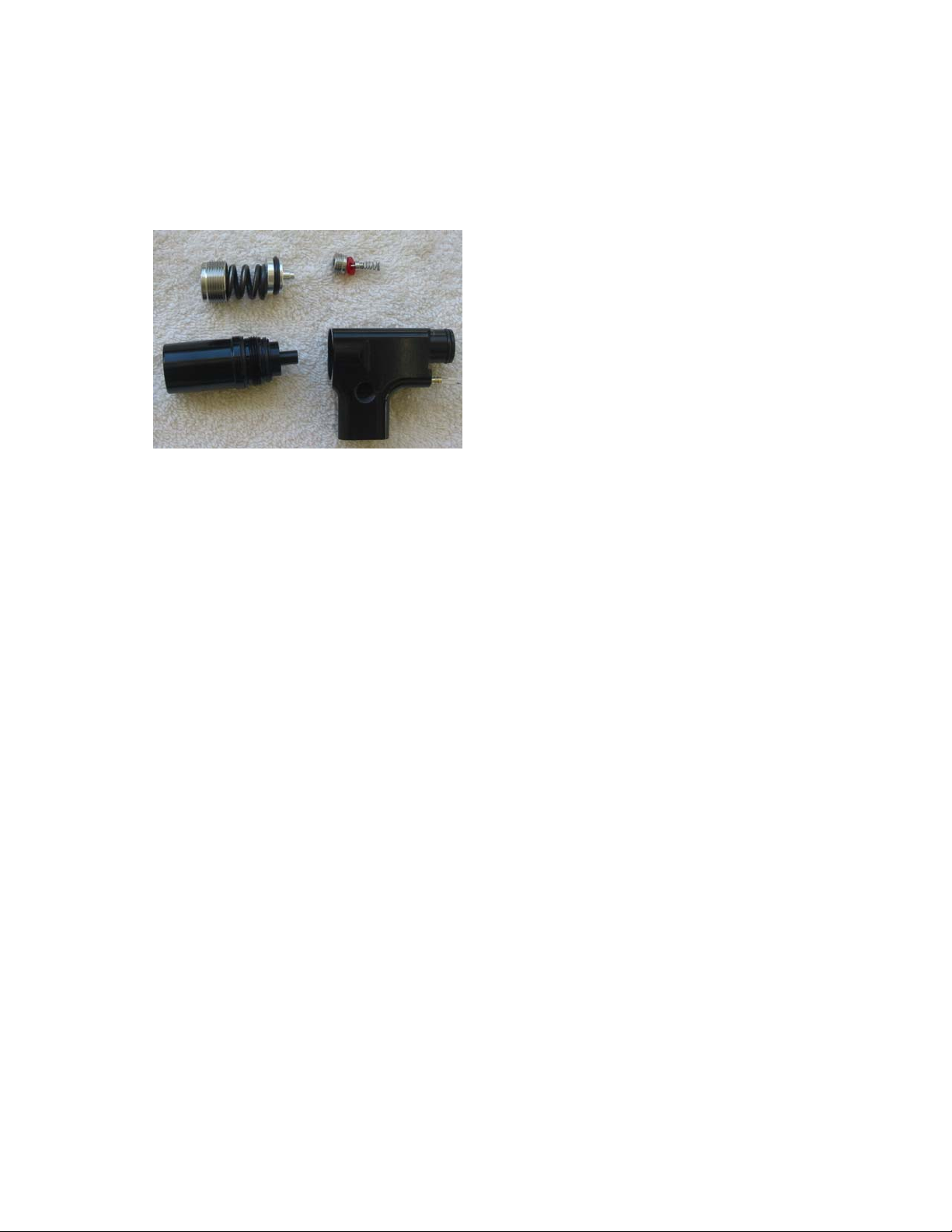
Low Pressure Regulator
Interceptor’s LPR is similar to most designs found in use for paintball. The
shoulder of a pin presses against a sealing surface. A piston pushes against the
pin to allow air to escape between the
pin and seal. The pressure of the
escaping air pushes back against that
piston, compressing a spring until the
piston no longer presses against the pin
and air is sealed. Correct pressure. Air
is used, pressure drops, pressure
against springs is reduced, spring
expands pushing piston, piston pushes
pin allowing air to escape. Screw down
the cap for higher pressure. Unscrew
the cap for lower pressure. Perfect!
Well almost perfect. Imperfect seals and contaminated O-Rings cause creeping
air pressure. In the event of LPR malfunction degas marker.
First, put on Safety glasses or Paintball goggles!
Careful, the piston can shoot out of the LPR body when the LPR cap is off
causing injury or blindness!
Completely unscrew LPR cap. Check cap and spring. If they are dirty clean the
cap and spring. If the inside of the LPR body is clean then the piston O-Ring may
have become dry through repeated use. A few drops of the supplied synthetic oil
will again allow for the piston’s smooth travel. Apply directly to the outside of the
piston, push piston down and replace spring and screw cap back on and you
may have solved the problem. However do this only if you are in a real hurry and
intend to clean the piston after play. Do not gas the marker back up with the
piston pushed down and the cap not replaced. Piston can shoot out of the
LPR Body.
For monthly servicing, or complete cleaning of your LPR, first remove spring and
cap as above and place a few drops of oil inside LPR. Push Piston down. With
Safety glasses or Paintball goggles on, and pointing the marker towards
something soft and intended to catch the piston, gas up the Interceptor, the
piston will shoot out of the LPR.
Listen to the LPR. If there is a leak between the pin and seal you can hear it now
that the piston is gone. If it is leaking, degas marker and remove the seal cap
with a 3/16ths Allen head wrench. Remove pin and spring and clean all parts of
the LPR. Replace the spring, pin, seal and cap as one unit. Screwing them into
place with Allen head wrench. It is best to use a new seal. If you do not have a
7
Page 8
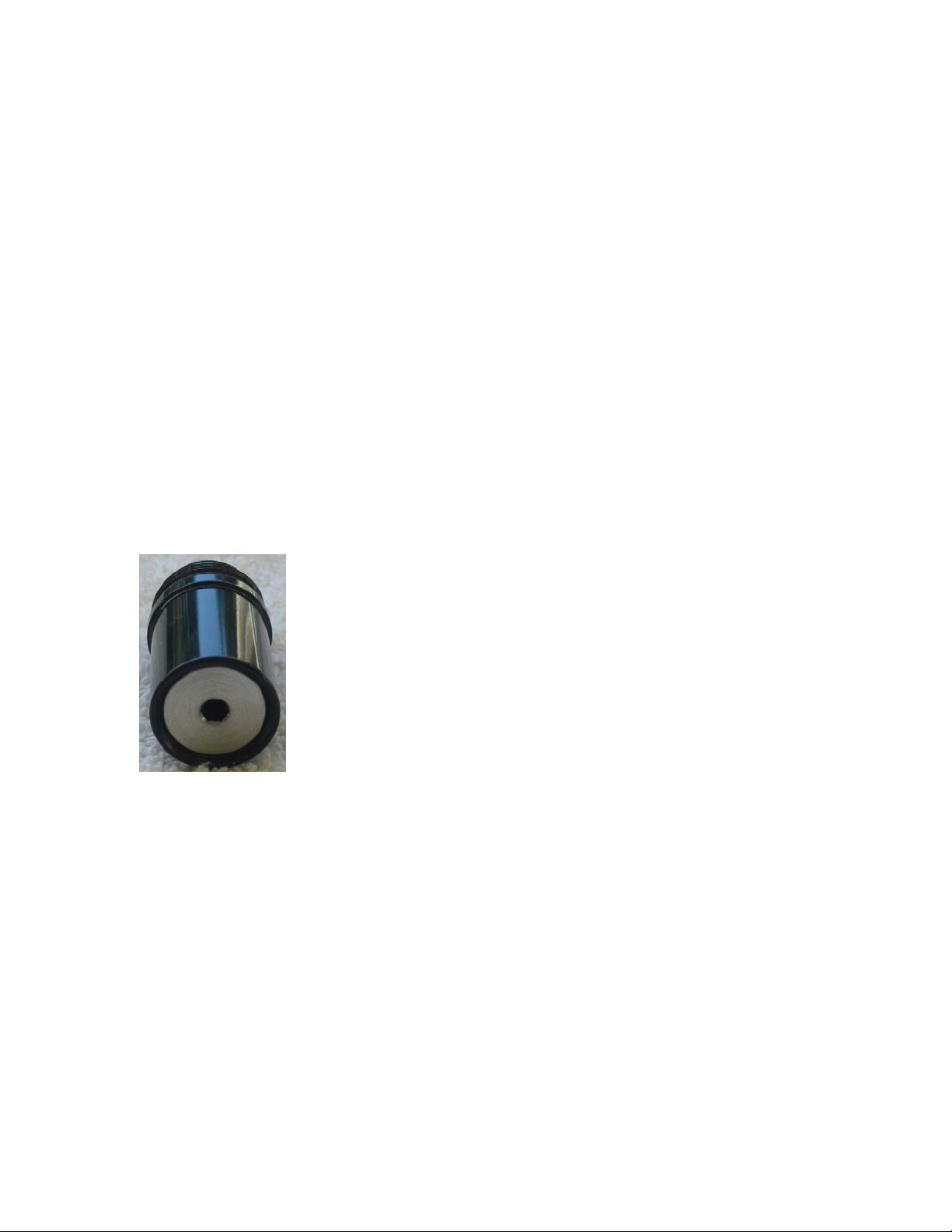
new seal then the best surface of the seal should be placed against the shoulder
of the pin.
If the seal is not leaking do not remove the seal and pin assembly, as the
assembly will last for a very long time is left alone. Look at the pressure gauge. If
you have degassed the marker and the gauge went to zero and then, after
gassing back up the gauge reads pressure again, the back O-Ring on the LPR
body is leaking. Remove the LPR from the Front Block and clean it. Replace ORing and lightly oil it. If you do not have a new 015 quad ring, inspect O-Ring. If
cut you can replace with bottle O-Ring, but they are too narrow and getting it to
seal may be difficult. Urethane rings will seal better than standard Buna rubber.
O-Ring creep is only possible if either air is escaping past pin and seal assembly,
or past back O-Ring.
Air leaking past Front O-Ring will have an audible leak from the surface between
the LPR body and the Front Block.
Air leaking out the front cap is caused by bad Piston O-Ring seating. Do not
degas! Slowly unscrew Cap and remove spring and piston. Check to see if piston
is tilted. If so the piston is dry, lubricate. If not then it is likely
that the O-Ring is cut or torn. Replace and lubricate. When
reassembling the LPR stack the cap, spring and piston and
lower the LPR body onto the three stacked pieces to that the
piston does not get tilted when assembling them. Tighten the
cap to just flush and the gas the marker up to make the final
LPR adjustment.
Hopper and Paint
The interceptor is capable of extremely fast firing and only the fastest hoppers
are capable of keeping up with it and demonstrating is full capabilities. Likewise
the use of top quality paintballs will be necessary for highest performance and
accuracy. NOTE: The Interceptor anti-chop eyes can be fooled by sunlight. Take
the hopper out and let the sunlight hit the eyes and you will notice the LED will go
from blinking green to pulsating green even without a ball in place. Therefore the
use of clear hoppers is not recommended with the Interceptor. While a clear
hopper can be used, you will likely find that the use of clear hoppers on sunny
days will cause your Interceptor to skip and chop at high rates of fire.
8
Page 9
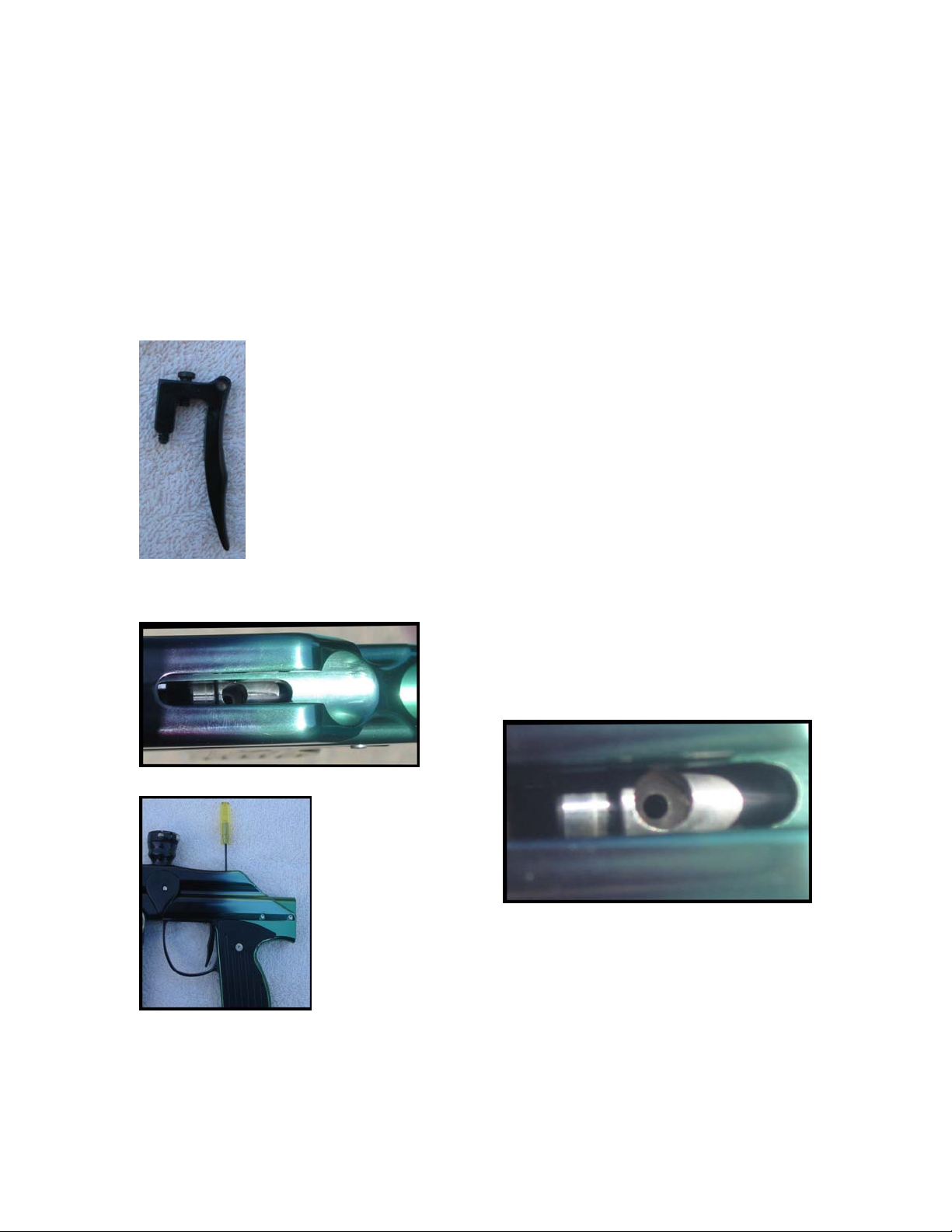
Setting the trigger pull
Your Interceptor has been designed so the trigger travel can be easily adjusted
without disassembly of you marker. The contact point is fixed. There are two
adjustments, one for forward travel and one for backward travel. Adjustments are
made with Allen head drivers, 1/16 for the front screw and 5/64 for the back
screw. Both adjustments are accessible by removing the bolt and looking
down to see the hammer. When the hammer is back you can see the trigger stop
plate.
Back setscrew hits ledge in trigger frame. Front cap screw hits
plate.
The front screw limits the travel after the switch is activated. The
setscrew hitting the “stop plate” limits travel. This plate is
also what the return spring rests against. Again the front hole in
the trigger plate accesses the screw to adjust the travel past the
firing point. Turning clockwise lowers the screw and increases the
travel. Turning counter clockwise raises the screw and limits the
travel.
Move the hammer forward 1/2 inch or so and you will be able to look through the
hole in the hammer to see the back hole in the stop plate. To adjust the travel
before the switch is activated, place an Allen
head wrench through the hole in the hammer
and through the hole in the stop plate and
into the screw.
NOTE: the two
adjustment screws
are opposite.
Screwing clockwise
increases the travel
on one, but decreases travel on the other. Make small
adjustments until you are sure which way you need to turn.
Half turns are adaquate. Large movements mean you are
turning the wrong way.
9
Page 10

Electronics
Equalizer
TM
Usage in Alien Interceptor
Equalizer is a trademark of Wicked Air Sportz
Revision 1.2- 05/05/05
All material including, but not limited to photographs, text, and concepts contained in
this manual is copyright ©2003-2005 By Wicked Air Sportz and Jim Drew.
Distribution of this data without permission is strictly prohibited! All rights reserved,
worldwide.
All material including, but not limited to photographs, text, and concepts contained in
this manual is copyright ©2004-2005 By Wicked Air Sportz and Jim Drew.
Distribution of this data without permission is strictly prohibited! All rights reserved,
worldwide.
USAGE
The Equalizer has numerous features, which can be a bit overwhelming
to those that are not use to having so much flexibility. However,
every possible step has been taken to make sure that the use of this
product is extremely simple.
Turning on the Equalizer
To turn on the Equalizer, press and hold the power button (located on
the back of the grip frame) for ½ of a second, and release it. The LED
should light solid orange or flickering orange and stay that way for
several seconds after releasing the button.
Turning off the Equalizer
10
Page 11

To turn off the Equalizer, press and hold the power button until the
LED becomes solid red, and then release the button. The LED will
blink red while the button is being held, this is normal.
Bypassing the Eye System
In order to be able to “dry fire” the marker, the eye system must be
bypassed. When the eye system is enabled, the marker will not fire
unless there is something in the breech. To bypass the eye system,
press and hold the power button for ½ second. The LED will then blink
orange (instead of green) indicating that the eye system has been
bypassed. Repeating this procedure will enable the eye system.
General Usage Tips
The LED boot sequence is as follows: solid or flickering orange
(booting), followed by either solid green (normal mode) or solid red
(competition mode). The LED will be flickering orange at boot-up if
the Firing Mode is not set to semi-auto. Viewing the LED boot-up is an
easy way for tournament organizers to determine if the marker is in a
semi-auto mode, and/or locked.
The rate of fire is limited only by how fast the pneumatics will cycle,
how fast you can pull the trigger, and how fast your loader can feed
your marker.
Because the Equalizer can easily exceed the feed rate of any loader in
existence, it is recommended that you use a force-feed type of loader
for the best possible performance.
LED Colors and Meanings
The LED used with the Equalizer can light up in one of 3 different
colors. The Equalizer
events are occurring. This is a breakdown of what the LED states
represent:
Blinking Green (once per second): Normal operation, anti-chop system
is enabled, Eye Mode 1 (rate of fire capped at user preset).
Blinking Green (twice per second): Normal operation, anti-chop
system is enabled, Eye Mode 2 (unlimited rate of fire).
uses this to indicate to the user when certain
11
Page 12

Blinking Orange: Normal operation, anti-chop system is disabled.
Blinking Red: Battery is low.
Red/Green toggle: There is an error with the anti-chop system (Eye
Mode 2 only).
Flickering green: object is in the breech.
Tournament Lock
It is possible to put the Equalizer
(COMPETITION) mode. You can do this by making sure the power off,
grounding (connecting) the two center pins on the Equalink interface
connector, and then turning on the power. Each time you ‘reboot’ with
the pins grounded, the NORMAL and COMPETITION modes will toggle.
The marker will not fire with the jumper in place! Removing the
jumper will allow the normal operation of the marker.
You can also change the tournament lock mode using the Equalink.
It is necessary to remove the battery after changing the
tournament lock or using the Equalink to alter settings or
update firmware.
into a tournament lock
Trigger Programming
The Dwell, Debounce™, Eye Mode, BIP Delay™, ROF Cap, Eye Power,
and Firing Mode functions are programmable by following these
instructions:
Make sure the power turned off. During trigger programming, make
sure that your marker has a barrel condom in place and the air supply
shut off. Although it is not possible to fire the marker while in
programming mode, it is always good to practice safe marker
handling.
Pull the trigger, and hold it in the back position. Now, press and hold
the power button for ½ second. During this time, the LED will light up
green.
12
Page 13

Now, release the trigger. The LED will light red. The marker is now in
“trigger programming mode”.
Pulling and releasing the trigger will change the LED color, advancing
to the next programming feature. This is also known as the
“programming menu”. The following colors equate to the feature
selected:
Solid Red: Dwell programming mode.
Solid Green: Debounce™ programming mode.
Solid Orange: Eye Mode programming mode.
Flickering Red: Ball In Place (BIP) Delay™ programming mode.
Flickering Green: Rate of Fire (ROF) cap programming mode.
Flickering Orange: Eye Power programming mode.
Alternating Green/Orange: Firing mode.
Once you have reached the last feature (alternating green/orange), an
additional trigger pull will start the sequence of colors over again. This
is also known as the “programming menu start”.
When you decide which programming feature you want to change, pull
the trigger and hold it until the LED goes out, and then release the
trigger. There will be a 2 second pause, and then the LED will flash
the same color of the programming mode you are in (red=Dwell,
green=Debounce™, orange=Eye Mode, etc.) the number of times that
represents something associated with that feature. For example, if
you were programming the Debounce™ and the settings were the
factory default (10ms), you would see the LED flash green 10 times in
a row, indicating the Debounce™ is set to 10ms. The flashing of the
LED shows you the current setting before you change it.
Once the LED is done flashing, there is a 5 second time period to begin
programming the new setting. To change the setting, pull and release
the trigger the number of times equal to how you wish to program the
feature. On each pull of the trigger, the LED will light up (indicating
that the pull has been detected). If you decide not to change the
feature setting at all, simply do not touch the trigger at all for 5
seconds. The LED will then blink green/red alternately to indicate
there was a programming error, and then go back to the programming
menu. The feature setting will not be changed.
Once you have pulled and released the trigger the number of times
you wanted the feature setting to be, do not touch the trigger. After 5
13
Page 14

seconds, the LED will flash a rainbow of colors indicating that the
feature setting change has been accepted. After this, the marker is in
the programming menu again. If you program a feature outside of its
specifications (for example, programming the dwell to 1ms) the LED
will blink green/red alternately indicating that there was a
programming error.
Each feature and its programming are described in detail below:
Dwell
Trigger programming for changing the dwell is different than any other
feature as there are two steps involved instead of one due to allowing
for .1ms (tenths) increments.
After selecting the Dwell programming feature, and once the LED stops
flashing, you can now pull and release the trigger once for every FULL
1ms of time you want the dwell to be. Once you have pulled the
trigger the number of times you want the full milliseconds to be, after
a 2 second pause the LED will blink orange and then off. You can then
pull the trigger again, but this time with each trigger pull being 1/10th
of a millisecond (.1ms). So, if you wanted to set the dwell to be
6.3ms, you would select the dwell programming mode by
pulling/releasing the trigger until the LED was solid red. Next, you
would hold the trigger until the LED went out. Next, the current dwell
setting (say 7.5ms) would be shown as 7 red flashes, a pause, an
orange flash, a pause, and then 5 red flashes. The orange flash is
th
there to separate the full milliseconds from the 1/10
of a millisecond
(.1ms) intervals.
The default dwell is 8.0ms. The lowest allowable dwell time is 4.0ms
and the longest allowable time is 50.0ms. According to the solenoid
manufacturer, the dwell should never be below 6.0ms for proper
operation.
Debounce™
Pull and release the trigger once for every 1ms of time you want the
setting to be. For example, if you were programming the Debounce™
to 5ms, you would pull and release the trigger 5 times. The default
Debounce™ setting is 10ms.
14
Page 15

Eye Mode
Pull and release the trigger the number of times necessary to set the
Eye Mode to what you want to use.
The following is a list of the possible Eye Modes and the flashes (also
trigger pulls required):
1 flash - Bypassed mode
2 flashes - Eye Mode 1 (uses rate of fire cap)
3 flashes - Eye Mode 2 (monitors bolt)
4 flashes - Simulate mode
If you pull and release the trigger more than 4 times, then the LED will
toggle green/red alternately to indicate there was a programming
error, and then go back to the programming menu. The default Eye
Mode is 2.
BIP Delay™
Pull and release the trigger once for every 1ms of time you want the
setting to be. For example, if you were programming the BIP Delay™
to 5ms, you would pull and release the trigger 5 times. The default
BIP Delay™ setting is 3ms.
Rate of Fire (ROF) Cap
Pull and release the trigger once for the number of times you want the
Rate of Fire (ROF) cap to be. For example, 20 pulls/releases would be
20 bps. The ROF cap is only used with Eye Mode 1. In Eye Mode 2,
the rate of fire is unlimited. The default ROF Cap is 15 bps.
Eye Power
Pull and release the trigger once for the number of times you want the
Eye Power to be. Each trigger pull represents a level increase. So, a
setting of 5 would make the eye more powerful (able to see through
15
Page 16

liquid paint) than a setting of 4. Higher values use more battery life.
The default Eye Power is 10.
Firing Mode
Pull and release the trigger the number of times necessary to set the
Firing Mode to what you want to use.
The following is a list of the possible Firing Modes and the flashes
(trigger pulls required):
1 flash - Semi-auto (NPPL legal)
2 flashes - 3 shot ramping (PSP legal)
3 flashes - 3 shot full auto (NXL legal)
If you pull and release the trigger more than 3 times, then the LED will
toggle green/red alternately to indicate there was a programming
error, and then go back to the programming menu. The default Firing
Mode is 1.
Programming Complete
Once you pulled and released the trigger the number of times
necessary to set the function, wait a few seconds. The LED will flash
red/green/orange in rapid succession (numerous times) to let you
know that the new setting has been saved. After this, the LED will
return to the color representing what the current programming menu
item is. At this point, you can once again pull and release the trigger
to toggle between Dwell, Debounce™, Eye Mode, BIP Delay™, ROF
Cap, Eye Power, and Firing Mode programming modes.
You can perform a complete reset, restoring all settings to the factory
defaults. To do this, just hold down the trigger for 6 full seconds. It
does not matter what programming mode you are currently in. The
LED will start flashing red, letting you know that a reset operation is
being performed. After this occurs, you will be back to the
programming starting point. DO NOT release the trigger until you see
the LED flashing red or the reset will not occur.
Computer Programming Mode (Equalink)
16
Page 17

Just as with all other Equalizer boards, this version has an Equalink
port. This port allows customers to fine tune settings as well as
download the latest firmware updates for the board from our website
(free of charge!)
To get into computer programming mode, hold the trigger and press
the power button for ½ second and release the power button… but not
the trigger! Keep holding the trigger until the LED switches from the
normal green color to off. The Equalizer is now ready to connect to a
PC. If you accidentally get into computer programming mode, you can
get out by pressing and holding the power button until it turns RED
and release it. If your trigger adjustment setscrew is adjusted too far
in so that it depresses the trigger switch when in the released position,
the marker will go into computer programming mode when it is turned
on!
Terminology
Dwell
Dwell is the amount of time that the solenoid will be activated. This
time is measured in milliseconds (1/1000th of a second). The user can
alter the Dwell only when in NORMAL mode. In COMPETITION mode,
the Dwell menu item is not available. Possible values are from 4.0ms
to 50.0ms. The factory default is 8.0ms. Changes are made in .1ms
units via the trigger.
Increasing your Dwell will increase the velocity of your marker. If you
are experiencing a great variance in your chrono results, try increasing
your Dwell and lowering your high pressure regulator. If your dwell is
too low, consistency will suffer greatly.
Debounce™
Debounce™ is the amount of time the trigger switch must be stable in
the up position before checking for another trigger pull. This time is
measured in milliseconds. The user can alter the Debounce™ only
when in NORMAL mode. In COMPETITION mode, the Debounce™
menu item is not available. Possible values are from 1ms to 50ms.
The factory default is 10ms. Changes are made in 1ms units.
17
Page 18

If you find that your marker is double firing, increase the Debounce™
time. To make your marker fire faster due to being more responsive
to the trigger, decrease the Debounce™ time.
Eye Mode
The Eye Mode is can be set to one of four different modes:
Bypass - The anti-chop system is disabled. When this occurs, the
maximum rate of fire is limited to 13 balls per second to help prevent
chopping of balls in the breech.
Eye Mode 1 – In this mode, the marker will not fire unless there is a
ball in the breech. This mode uses a rate of fire cap to determine the
speed of the cycling. The bolt is not monitored.
Eye Mode 2 - In this mode, the marker will not fire unless there is a
ball in the breech. This mode works by monitoring the bolt position,
and thus the rate of fire is unlimited. This is the default eye mode.
Simulate – In this mode, a ball is simulated to be in the breech. This
allows you to fire the marker with just air, at the full speed that the
marker is capable of firing! This mode can be used for practicing
trigger pull methods, without wasting paint. DO NOT SHOOT PAINT
IN THIS MODE!
BIP Delay™
The BIP Delay™ is a feature that allows you to adjust for the
differences in the eye sensor, its installation, and the loader being
used. When using a slower gravity-feed loader it may be necessary to
have a longer BIP Delay™ to prevent balls from being chopped.
Possible values are from 1ms to 50ms. The factory default is 3ms.
Changes are made in 1ms units.
ROF Cap
18
Page 19

The rate of fire (ROF) cap sets the maximum cycle speed of the
marker when Eye Mode 1 is used. Setting this value to low will reduce
the usable speed of the marker. Setting this value too high can cause
misfires if the marker pneumatics are very slow due to bad o-rings or
swollen bolt.
Possible values are from 10 bps to 30 bps. The factory default is 15
bps. Changes are made in 1 bps units.
Eye Power
The eye power controls how much power the eye system uses when
transmitting infrared energy to the receiver. Setting this value too low
will cause problems if debris such paint, dirt, etc. is between the
transmitter and receiver. Setting this value too high can cause
problems with paint that uses a clear shell (the infrared is transmitted
through the shell). Possible values are from 1 to 20. The factory
default is 10. Changes are made in 1 unit increments.
Firing Mode
The Firing Mode determines how the marker will fire. Possible modes
are semi-auto (one pull/release of the trigger fires the marker one
time), 3 shot ramping (adheres to the 2005 PSP rules), and 3 shot full
auto (adheres to the 2005 NXL rules).
The firing mode controls how the marker fires regardless of other
settings. For example, if the Eye Mode is set to Eye Mode 2 (unlimited
rate of fire), and the Firing Mode is set to 3 (full auto), then the
marker will fire in full auto as fast as the hopper can feed. Now, if you
changed the Eye Mode to Eye Mode 1 (capped), then the ROF Cap
would determine the maximum rate of fire while in full auto.
Reset
This option will reset ALL of the settings to the factory default! If you
find that you are having problems remembering the factory defaults,
just use this option to reset your board and start over! The user can
reset the board only when in NORMAL mode.
19
Page 20
This is the end of the copyrighted Wicked Air Sportz Equalizer use section. Hope
you got all that!
Disassembly
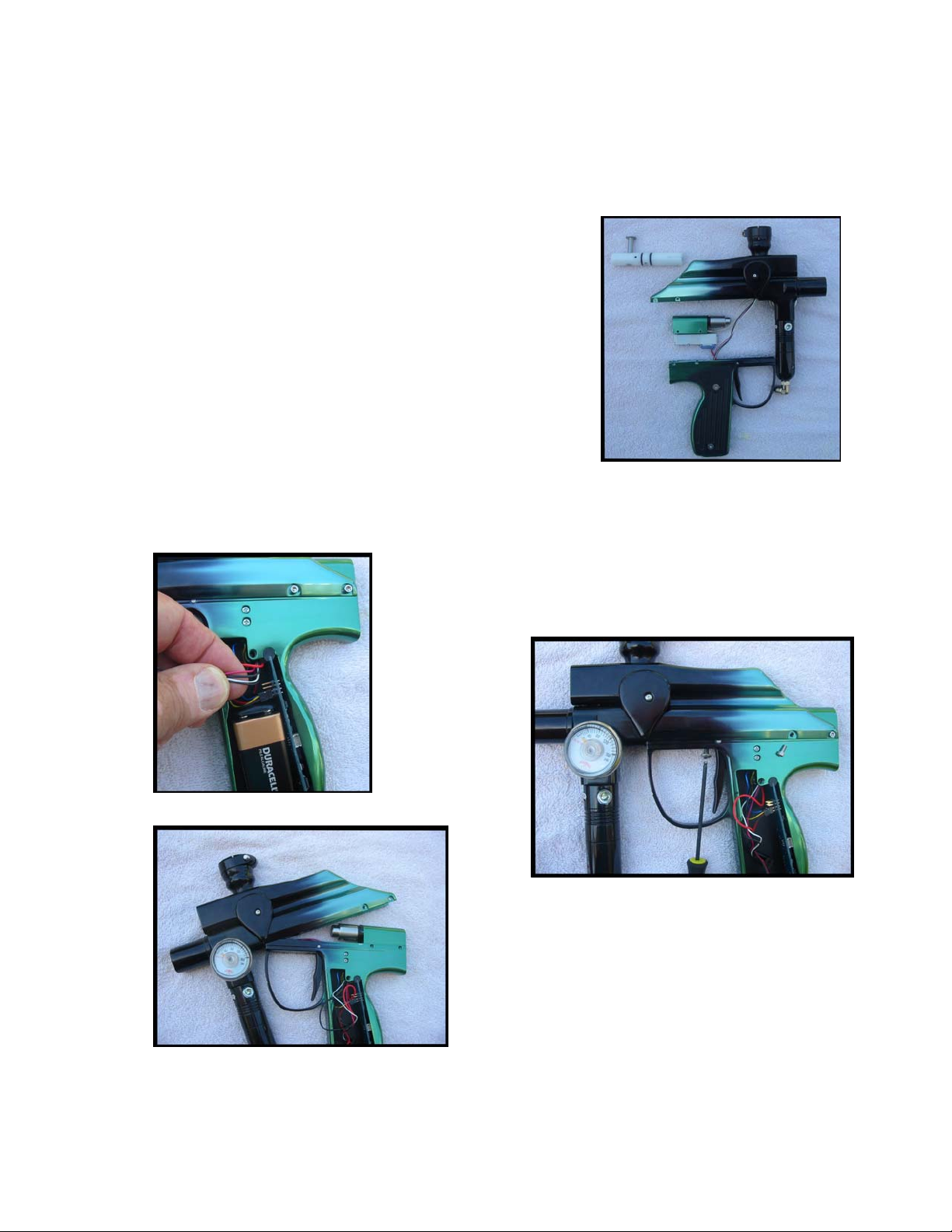
The Interceptor can be pulled into its three main
pieces, powered up and fired. Each piece is visible,
most O-rings can be inspected for leaks, both ends of
the hose can be inspected and the pin valve is
accessible. This ability makes the Interceptor
exceptionally easy to trouble shoot. Problems are
found quickly and easily, and are just as easy to fix.
To disassemble:
First, remove the bolt, then open one of the side panels and make sure the wires
are loose. Bottom wiring harness goes to the battery and switch. Top wiring
harness has four wires, - two black one red and
one white - loosen them and kind of push them up.
Second, take the four screws off the back of ram
and the one off
under the
trigger guard
and gently pull
the marker
apart making
sure the ram
stays attached
to the
trigger
frame.
Hinge it apart if it's a bit sticky. It will
easily come apart but be careful not to it
pull on the wires. Wires should easily slide
up from trigger housing. Feed the wires
up as necessary.
20
Page 21
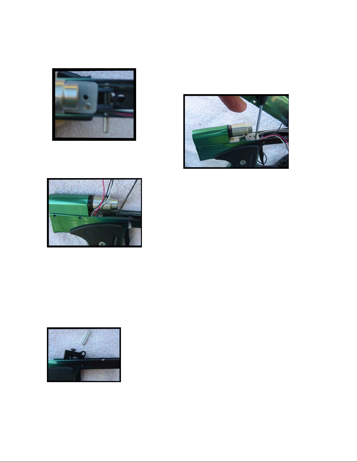
Third, the limiting factor is the fact that the hose and wires must fit under the
trigger stop plate.
Note that the hose is on one side of the stop plate
and the wires are on the other. Remove the screws
with a Phillips screwdriver and remove the trigger
stop plate.
Remove the trigger spring in the trigger.
Additionally note that the eye wires go
along the side of the solenoid but in front of the
ram body.
The wires slide easily between the stop plate and
the frame; and between the side of the solenoid
and the trigger frame body. PULL the four wires
partially up and out of the trigger frame noting how
much slack is left in the trigger frame.
Forth, put the plate, the two screws and spring in a small receptacle so they don’t
get lost.
Fifth, you can now air the marker up and turn on the power. You may first want to
turn the LPR down to 40 or 50psi. Watch out when you pull the trigger as the
ram will jump and the ram can pinch you fingers pretty hard between the ram
body and the hammer
Sixth, you may want to take the pin out and remove the
trigger to clean and “lightly” oil it. In the case of a sticky
trigger the stop plate does not have to be removed and
the ram does not have to be taken out of the grip frame.
Push the trigger pin out and clean pin and clean the
inside of the trigger with a Q Tip
21
Page 22
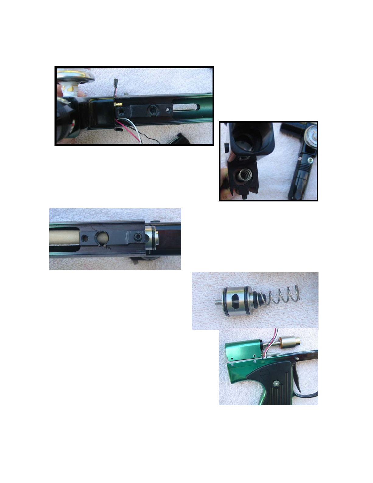
Seventh, to inspect or repair the pin valve assembly, first DEGAS, then remove
the eye covers. Next remove the two adjoining setscrews on the bottom of the
body, one for the front block
and one for the pin valve.
Remove the Front Block; the hose can be left
attached to the ram. Place the Valve pin, valve
spring and the two setscrews in a small
receptacle so they won’t get lost.
With a wooden dowel, and pushing from
the back of the valve towards the front
of the marker, push the valve out of the
receiver body. The valve’s sweep
features are now visible, the oval outlet
hole and the radius on the valve’s back
wall.
Eighth, In the event a leak is coming
from the ram housing area you will want
to remove the ram from the trigger grip.
Ram is removed by pulling the ram straight up. If
it is sticking try carefully rocking it sideways
noting that the ram is quite close to the trigger
switch connectors and that you don't want to
break the wires off of the trigger switch. If you
have to, extend the ram and slowly rock up and
down on the hammer until rams loosens.
22
Page 23
It is best NOT to take the board out of the marker! The alignment of the board in
the marker is critical to the proper operation of the On Off switch, the On Off pin
is easily lost, and the Equalink port can be broken while sliding the board back
into place. No repairs or service is useful by removing board. Should the On Off
pin become so dirty as to be unmovable it would be better to remove the wiring
harness and wash the trigger frame with the board in place than to remove the
board.
Reassembly
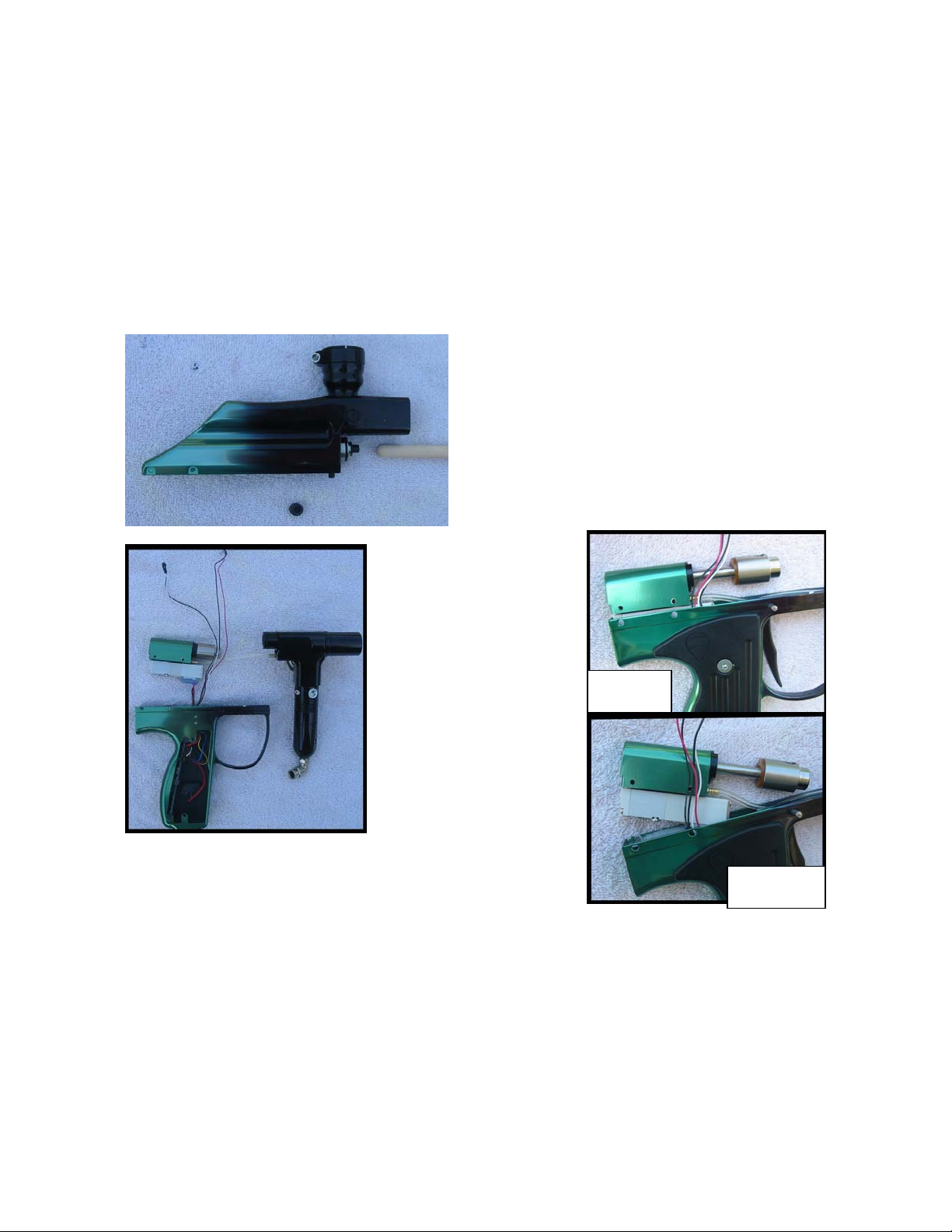
First, put the pin in the valve. While
pushing on the valve pin and carefully
aligning the valve body so that the ORings are not cut, slide the valve into the
body making sure the hole is at the top
and the alignment recess for the setscrew
is at the bottom. Setscrew the valve in
place once valve properly centered. Place
the spring on the valve pin.
Second, the eye wires
are almost all the way
out of the trigger
grip, you have some
room to move.
Slide ram back into
trigger frame. Make
sure solenoid wires are
pulled into trigger
frame so they don’t
interfere with ram
seating or trigger
movement. Also note
the eye wires. Eye wires slide easily between trigger
frame and the solenoid. Be certain to slide Ram
straight down. Do not rock ram into place. Properly
aligned, the ram will have very little or no resistance. Look at the back of the ram
and solenoid, and at the side where the eye wires are and lower it straight into
grip frame.
Right
Wrong
23
Page 24
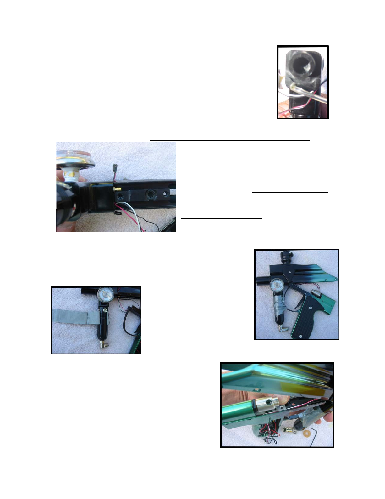
Third, note the channel cut into the front block for the wires.
Note the wire groove that is formed between the front block and
the body when placed together. At all times BEING CAREFUL
not to crush the eye wires between the front block and the body,
proceed. Slide front block into receiver just past the O-Ring.
Align wires so that wires are going down the channel opposite
the hose channel. The wire coming from the hose side needs to
be under the hose. Twist the front block back and forth in
relation to the body to route eye wires past hose. Once the
wires are correctly routed under the hose and into the wire channel push the front
block snug against the body. BEFORE you tighten the setscrew for the front
block, remove the eyes from the body and
make sure eye wires slides easily and that
wires are not between the block and the
body. Once the wires move easily and the
front block is pressed flat against the body
tighten the setscrew. If there is even a small
gap between the body and the front block
do not tighten. Tightening will crush the eye
wire and disable the eye. Often the eye
wires go right into place and this is a very
quick and easy step, BUT it can seem
much more difficult than it is and getting the wires to lie in the channel can be
frustrating.
Forth, it is easier if you take a
piece of tape and wrap it all
the way around the regulator
first to avoid scratches.
Trigger frame rests inside the
body cuts, tape the trigger
guard to the regulator.
Place the trigger spring back into trigger. Pull
excess wires into frame, push hammer back
into ram. And route hose into groove next to
trigger. Straighten wire along side of trigger
frame and into groove next to trigger and
opposite hose. Align trigger stop over screw
holes in trigger frame and over trigger return
spring.
24
Page 25
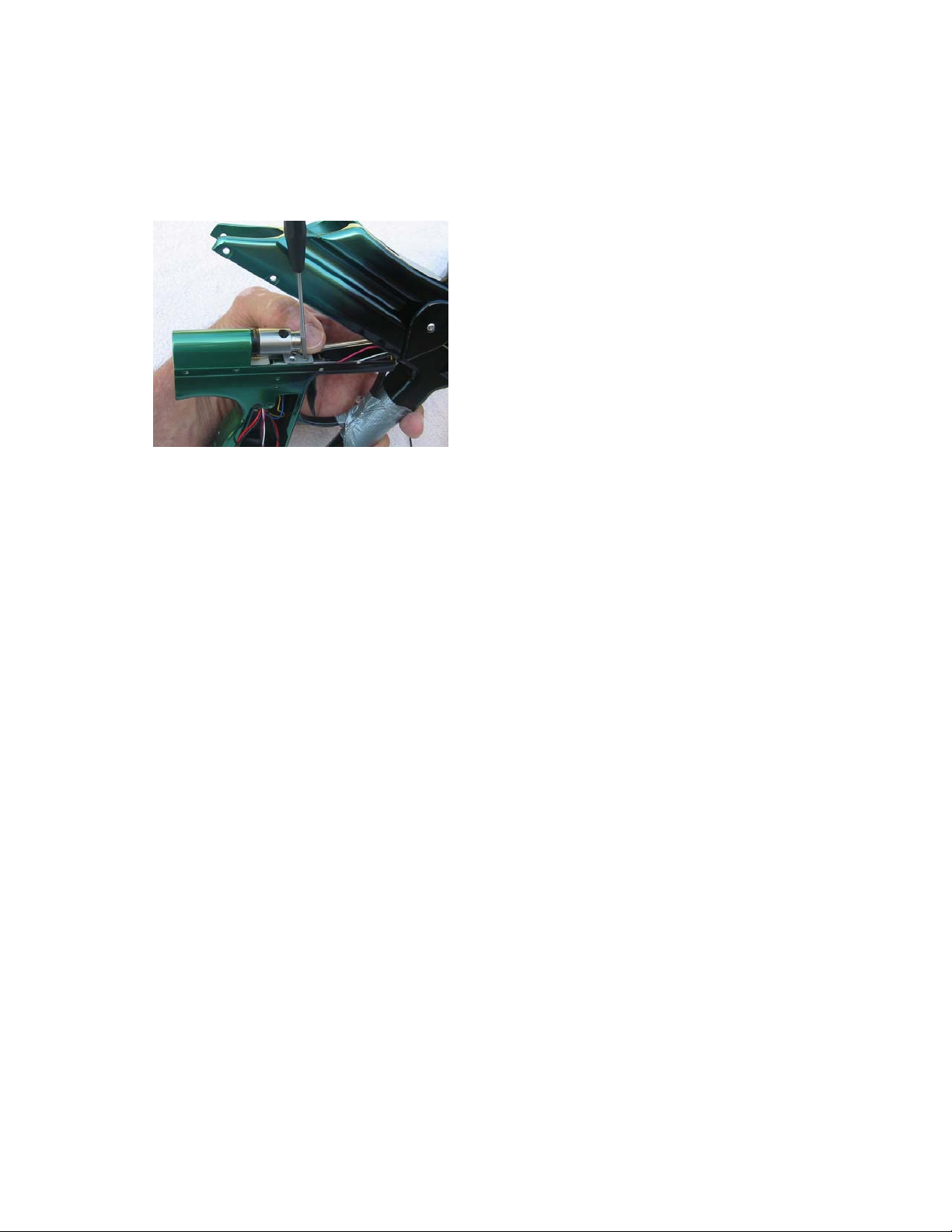
Start screw in front screw of trigger plate. Check that all wires are in groove and
tighten, do not over tighten. Slide hammer forward and screw in second screw.
Align hammer so the hole is at the top.
Note: If I can hold all the pieces and
balance the screwdriver with one hand
and take the picture with the other you
can hold the wires and hose and get the
screw started with two hands!
Sixth, Rotate body and align the holes in
the ram, body and trigger frame. Pull the
wires into the trigger grip. It can help to first pull the wires back under the trigger
plate and then into the grip frame, however so long as the wire are straight they
can often be pulled straight into the trigger. If wires are not properly aligned they
will get crushed between the body and trigger frame. It is helpful to place a little
bit of tape on the wires to hold them against the side of the trigger frame. Once
you are satisfied that the wires are properly aligned and all excess wire is pulled
into the trigger frame, hinge the body completely up.
Seventh, Replace the 5 screws. Start all the screws but DO NOT tighten them.
The proper ways to align any screw is to make sure it is perpendicular to the hole
and then turn it counterclockwise until it clicks (assuming a standard right
threaded screw). The click tells you you've just past the start of the threading of
both the screw and the hole. Start turning clockwise and the screw will start to go
in. Any binding at this point tells you that the screw is not properly aligned, do not
force. Unscrew counterclockwise until you feel and hear the click, then recheck
the alignment of the screw to the ram body and screw it in. Do not over tighten.
You can get plenty of pressure by holding the short end of most Allen sets.
Tightening by holding the long end of an Allen wrench gives enough force to strip
out the screws. DO NOT OVER TIGHTEN.
Eighth, before you air up, check to be sure the hammer is aligned so the hole is
to the top. If hole does not face the top, reach down with a tool and spin the
hammer. If it doesn't spin check to make sure the air is off and the marker has no
pressure. The hammer can be turned while the marker is gassed up but it takes
substantially more effort. Once aligned, place bolt into body and push bolt pin
into hammer.
25
Page 26
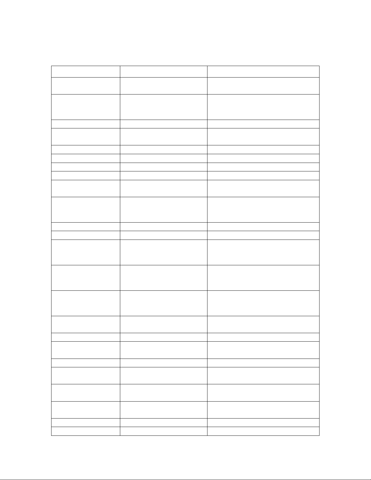
Troubleshooting
y
Problem Cause Repair
Inconsistent Shots Inconsistent Hammer
speeds.
Dirty bolt causing
sticking
LPR piston is sticky, dry Remove, clean and lube
Low power supply Use fresh, high quality, alkaline
Low dwell setting Turn up dwell
Creeping LPR Dry O-Ring Remove Clean and Lube
Dirty O-Ring Remove Clean and Lube
Bad or Dirty Seal Remove Clean and Lube.
Marker is on, bolt
is not firm
Marker won’t fire,
air on, and bolt is
firm
No ball in chamber Check for pulsating green light.
Won’t turn on Dead Battery Replace battery
Short in Electrical Turn battery harness around.
Unsure if trigger is
registering pull.
Trigger not
registering pull.
Eye Harness in
Trigger wires broken Replace trigger switch.
Trigger registering
pull, won’t fire.
Dwell is too low Set dwell higher.
Bolt pin in front of
Firing without ball
in place
Eyes are getting
Chopping balls Eyes bypassed Turn on eyes
E
Air is off Turn air on
Power not turned on Press on off button
Trigger has been set
incorrectly.
incorrectly
Air is off Turn on air.
hammer
Eyes bypassed Turn eyes on
sunlight.
es are getting Use dark Hopper
Turn up LPR until consistent
shot.
Remove and clean bolt.
Optionally lightly oil O-Rings
with approved oil.
batteries.
Check to see if any wires are cut
or squished
Press on/off to get blinking
orange. Pull trigger, led flashes
green, trigger is registering.
Turn front trigger set screw
clockwise until trigger has
enough movement.
Turn top harness around or align
pins correctly
Align bolt pin to hammer
Use dark Hopper
26
Page 27
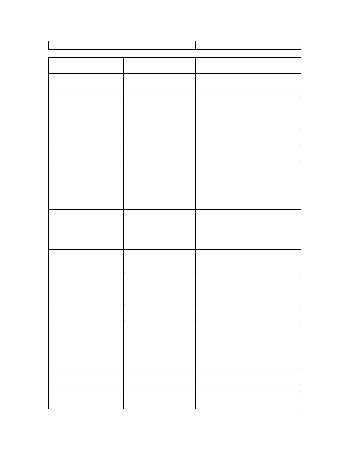
sunlight.
LED flickers green w/o
ball in place
Eye harness in
Eyes are getting
sunlight.
Use dark Hopper
Rotated harness or align to pins.
incorrectly
Double Feeding Worn Ball Detents Replace Ball Detents
Misaligned Detents Push shoulder of detent back
through hole in body. Repeated
misalignment can require a shim
between detent and eye cover.
Adding shots, going
Trigger is bouncing Set Debounce higher
“automatic”
Soft or missing
spring
Replace or increase spring
tension.
Sticky Trigger Paint in trigger Hinge trigger frame down by
removing the screw under
trigger frame and front two
screws. Remove trigger pin.
Clean pin and trigger. Check
wires when hinging back up.
Large amount of air is
escaping inside trigger
frame. Usually during
gassing up and a loud
Pop is heard.
Smaller amount of air
is leaking inside
Air line disconnected
from ram or front
block, usually
because of over
pressurizing of LPR
Over pressurized air
valve is leaking
Reconnect airline; check LPR
for leaking or creeping.
Turn down LPR, Check for
creeping LPR
trigger frame.
Air valve has come
Tighten valve to ram
loose from ram,
leaking around
solenoid
Hose is leaking Check for cuts, replace as
necessary.
Barbs are leaking Barbs are held in with sealer.
Barbs should not be tightened or
removed. Front block needs to
be separated from all other
parts. Then barb can be heated
and removed.
Blown valve due to
Return to manufacturer
overpressure
Dirt inside air valve Return to manufacturer
Deteriorated valve
Return to Manufacturer
O-Ring
27
Page 28

28
 Loading...