


- 1 -
8036 SIP Multimedia
Intercom
User Guide
Algo Communication Products Ltd.
www.algosolutions.com
260424-01

- 2 -
Table of Contents
Overview ........................................................................ 4
Introduction .............................................................................4
Key Features .............................................................................4
What’s Included .......................................................................5
Product Tour ............................................................................. 6
Setup and Installation .................................................... 7
Wall Mounting .........................................................................7
PoE Network Connection ........................................................15
Programming and Configuration ................................. 16
Web Interface Control Panel ...................................................16
Accessing the Control Panel ....................................................16
Setup SIP Account...................................................................18
Application Development ............................................. 19
Overview ...............................................................................19
Creating User Interface Screens ..............................................20
Custom Graphic Screens.........................................................20
Directory (Addressbook) Listings .............................................21
Uploading user content ..........................................................22
Control Panel Menu Reference ..................................... 23
Status ..................................................................................... 23
Settings ..................................................................................24
User Interface.........................................................................33
System ...................................................................................42
Door Control ................................................................. 45
Configuring the 8061 .............................................................46
Configuring the 8036 with the 8061 ....................................... 47
Door Control Hardware and Wiring ........................................47
Appendix ...................................................................... 48
Upgrade 8036 Firmware ........................................................48
Soft Reset ...............................................................................49
Button Positioning Table ..........................................................50

- 3 -
Directory (Addressbook) Text Files ...........................................53
Working with Compressed Files ..............................................55
Specifications .........................................................................57
FCC Compliance ....................................................................59
Important Safety Notice .......................................................... 59

- 4 -
Overview
Introduction
The 8036 is a multimedia SIP endpoint from Algo
combining the functionality of an IP phone,
security camera, and interactive kiosk.
Easily configurable to support multiple
applications and interface configurations,
the product is designed for outdoor or
public access locations to provide
enhanced communication and support for
guests and visitors.
Key Features
• Sunlight viewable 5.7” VGA color
capacitive touch display
• Integrated camera for still snapshot or H.264 video
streaming
• Weatherproof
• Wideband speaker and dual microphones
• Presence detection
• Secure door/gate management
• Web interface panel for configuration and application
programming
For comprehensive product and application information,
please visit www.algosolutions.com/8036

- 5 -
What’s Included
For information on the use of each of these components,
please refer to “Setup and Installation” on page 7.
Algo
Security
Tool
Ethernet
Cable Boot
#8 x 1
Type B
Pan Head
Phillips
Qty: 6
#8 x 1.5
Type A
Pan Head
Phillips
Qty: 6
Drywall
Bracket
Surface
Mount
Bracket
Mounting
Gasket
8036
Assembly
with
Front Bezel

- 6 -
Product Tour
Front View
Presence Detection
VGA H.264 Camera
“HD” Dual Microphones
Nickel Plated Cover
“HD” Speaker
Algo Logo Badge
covering Security Screw
Sunlight Viewable
Touch Display
SIP PoE
(Connector on Back)
Back View (of 8036 Assemby)
Weatherproof
Ethernet Cable
Boot
PoE Network
Jack

- 7 -
Setup and Installation
This section will guide you with the physical installation of
your new 8036 SIP Multimedia Intercom.
Wall Mounting
The 8036 can be either surface or flush mounted. The unit
is designed to shed rainwater and allow air ventilation only
when oriented in the correct position (ALGO logo at top) and
installed vertically.
Removal of Front Bezel for Installation
The 8036 is shipped partially assembled and must be
partially
disassembled before
it can be installed.
Remove the security
screw behind the
ALGO Logo Badge
by first pressing
on one side of the
badge. This will raise
the other side so that
it can be removed
easily by hand.
A security bit (“Algo
Security Tool”) is
included with the
8036 that fits standard socket screwdrivers. Use the bit in a
screwdriver to remove the security screw and carefully remove
the Front Bezel by pulling at the top and then disengaging the
bottom clip.

- 8 -
Algo
Security
Tool
Put the Front Bezel, Security Screw, and Logo Badge aside for
re-assembly after mounting.
Refer to the following diagrams for the appropriate methods
and components to use for different mounting applications.
Flush Mounting into Drywall (Interior)
1. Create a drywall cut out per the template on page 4 of
this sheet.
2. Place the Drywall Bracket into wall and bend tabs around
to the front of the drywall to hold in place.
3. After connecting the Ethernet cable, use the #8 x 1.5”
Type A Pan Head screws to secure the 8036 housing to
the Drywall Bracket.
4. Replace the Front Bezel and keep the Algo Security Tool in
a safe location.
5. Replace the ALGO Logo Badge.
The Mounting Gasket and Surface Mount Bracket are
not required for drywall mounting.

- 9 -
Flush Mounting an 8036 into an interior wall (drywall)
Front Bezel
#8 x 1.5” Type A Pan Head
(Typical) Six needed
8036 Assembly
Logo Badge
Security Screw
Under Logo Badge
Drywall
Bracket
Drywall
A template for cutting a hole in the wall can be
downloaded at
www.algosolutions.com/8036mounting

- 10 -
Flush Mounting into Other Materials or Outdoors
The same guidelines of flush mounting from the previous
section apply, however, the Drywall Bracket may not be
required if the wall material is firm enough to hold a screw
close to the cutout edge. A #8 anchor may be required (not
supplied) for the wall material.
If outdoors:
1. A rubber Ethernet Cable boot is supplied to be placed
over the network cable prior to terminating with a plug
(see “PoE Network Connection” on page 15).
2. While the 8036 is designed to withstand rain, it may be
undesirable for water to enter the wall cavity. This can be
achieved by sealing the cable hole prior to mounting or
using the Mounting Gasket between the 8036 and wall.
Uneven surfaces may require a silicon bead around the
8036 after installation.
Flush Mounting an 8036 into Drywall
Front Bezel
#8 x 1.5” Type A Pan Head
(Typical) Six needed
8036 Assembly
Logo Badge
Security Screw
Under Logo Badge
Drywall
Bracket
Drywall

- 11 -
Flush Mounting an 8036 into Drywall
#8 x 1.5” Type A Pan Head
(Typical) Six needed
Mounting Gasket
Anchors as
Required
Apply thin silicone seal around
opening (mount, then seal)

- 12 -
Surface Mounting
The Surface Mount Bracket may be used on a wall surface
where flush mounting is undesirable, or not practical. The
bracket also may be good option when integrating the 8036
into stonework.
1. Mount the Surface Mount Bracket using the #8 x 1.5”
Type A Pan Head screws supplied. For some wall
materials, #8 anchors may be required (not included).
There is a top and bottom to the Surface Mount Bracket. Make
sure the two drainage holes are at the bottom.
If outdoors:
a. Ensure any opening in the wall is sealed or apply a
silicon bead between the Surface Mount Bracket and
wall surface around the outside perimeter.
b. The Ethernet Cable Boot is to be placed over the
network cable prior to terminating with a plug (see
“PoE Network Connection” on page 15).
c. To prevent water from getting behind the 8036, place
the Mounting Gasket on to the back of the 8036
housing prior to mounting.
2. After connecting the Ethernet cable, use the #8 x 1” Type
B Pan Head screws to secure the 8036 housing to the
Surface Mount Bracket.
3. Replace the Front Bezel and keep the Algo Security Tool in
a safe location. Replace the ALGO Logo Badge.
The Drywall Bracket is not required when surface mounting.

- 13 -
Surface mounting an 8036 on outside wall
#8 x 1.5” Type A Pan Head
(Typical) Six needed
#8 x 1” Type B Pan Head
(Typical) Six needed
Surface Mount Bracket
Optional: Apply thin silicone seal around
perimeter (mount, then seal)
Mounting Gasket

- 14 -
Mounting Height
The 8036 should be mounted at an appropriate height for
your intended application. The considerations are:
1. Easy readability of the interface screens for users of
different heights
2. Highest quality camera and video images.
For most applications, a mounting height of approximately
55 inches (1.4 m) from floor to center of display is
recommended.
Mounting the 8036 at the proper height
0
1
2
3
4
5
6
123 0
Measurements in Ft.
Typical 55” (1.4m) to center of 8036
(i.e. middle mounting screw)
97˚ VFOV (x 106H)

- 15 -
PoE Network Connection
The 8036 is powered by the Ethernet PoE network connection.
Typically a network cable is run to the 8036 location and then
terminated with a male RJ45 plug.
If you don’t have a PoE switch, you’ll need a PoE
injector that installs between the 8036 and the network
switch. The PoE injector will supply 48 Vdc to the 8036.
Ensure that the PoE injector is fully compliant to the
IEEE 802.3af standard.
If mounting outdoors, slide the Ethernet Cable Boot onto the
cable before installing the RJ45 plug.
Ethernet
Cable
Boot
PoE
Network
Jack
RJ45 Plug
8036
Back
After inserting the plug into the 8036 jack, carefully position
the boot into the jack cavity to prevent moisture or insects
from getting inside.
When inserting
the plug into the
jack, be sure the
plug lock tab is
not accidentally
depressed, creating
a loose connection.
Lock Tab

- 16 -
Programming and Configuration
Web Interface Control Panel
Primary configuration of the 8036 is through the web
interface control panel. Here is where you will be able to set
up your 8036 and also develop interface screens to create
interactive applications.
Accessing the Control Panel
To access the 8036 Control Panel, you first need to determine
the 8036’s IP address and then enter this address into a
browser.
Find the IP Address
After connecting the 8036 to a network PoE port, the 8036
will attempt to obtain an IP address from the DHCP server
and display this on the screen.

- 17 -
If this is the first time you are using the 8036 and no user
interface has yet been set up, you will be displayed the
Welcome screen to the right which provides the IP address. If
a User Interface already exists, the IP address will be shown
for a few seconds at boot time, before the splash screen
appears.
You will need to know this IP address in order to access the
web interface tool.
If the 8036 in unable to obtain an IP address from the DHCP
server, it will default to the fixed IP address 192.168.1.111.

- 18 -
Web Configuration Panel
Point your web browser to the 8036’s IP address. This brings
up the login page. The default password is algo.
Once logged in, the Status page is shown which welcomes
you to the program (see “Control Panel Menu Reference” on
page 23). From here you can access all of the
configuration options for your 8036 device.
Setup SIP Account
The SIP account and related settings can all be found in the
Settings>SIP section. This configuration will make the 8036’s
location known and allow the 8036 to make and receive
calls. You must have a valid SIP account. You can get more
details from your System/Network Administrator to fill in this
section.

- 19 -
Application Development
Overview
With the 8036 you can easily design, implement, and update
custom user interface screens and functions that help you
communicate most effectively with visitors and guests. For
example, you can make attractive landing pages with your
company logo and graphics. On it, you can have buttons that
make calls or that lead to various information or directory
pages.
Example 8036 Custom Graphics Screen using 3 x 3 Full Button layout with four
active buttons
You can set all of this up using the 8036 Control Panel. You’ll
also be able to back up all the configuration and user
interface information to a PC for safekeeping.

- 20 -
Creating User Interface Screens
The key to an effective implementation of the 8036 is to
configure a package of interface screens that fulfill the
various visitor functions you require. You do this easily
through the User Interface menu in the 8036 Control Panel
(see “User Interface” on page 33).
For a basic implementation, you can set up simple screens
and pages using the generic button graphics and background
screens provided with the system. You can also easily create
graphics screens developed with standard image editing
programs and then import them into the 8036. Either
way, you can set up multiple pages with different button
configurations and layouts, enable or disable specific button
locations, and set different actions associated with each
button.
You can also import tab-delimited text files containing names
and numbers and have the 8036 display a directory whereby
visitors can call individuals directly.
Custom Graphic Screens
To develop custom interface screens you need to be able to
create 640 x 480 pixel graphic files in the PNG (Portable
Network Graphics) format. Most graphics/image editing
programs (such as Adobe® Photoshop®) have this capability.
Within the graphics program you can create your own
background and button graphics and then align the button
graphics (if used) to the layouts you have chosen for your
8036 User Interface.
The User Interface configuration allows you to create several
types of pages with different button configurations. For
information on the different types of button layout pages
possible, please refer to the “Button Positioning Table” on
page 50.

- 21 -
For example, here is a standard Two Button page layout in
combination with a custom 640 x 480 PNG graphics file to
create a simple Welcome page for visitors.
Directory (Addressbook) Listings
You can also upload tab-delimited text files to allow the 8036
to display directory pages. You can then set up pages to use
these directory files to display a call directory for visitors to
use. For more information, see “Directory (Addressbook) Text
Files” on page 53.

- 22 -
Uploading user content
Before configuring a custom user interface, all the images,
directory text files, and other resources that will be used by
your UI must first be uploaded to the 8036.
You can upload individual files as you need them (see or you
can upload content files in bulk using a properly formatted
compressed file (in .tar.gz format). For more information on
this, please see “Working with Compressed Files” on page
55.

- 23 -
Control Panel Menu Reference
Status
Introduction
This screen provides a quick guide to setting up your 8036. It
covers four key steps:
• SIP Configuration
• Network Settings
• Securing the 8036 with a Password
• Customer Registration with Algo
In addition, this screen provides the current status of the
8036 in regards to SIP Registration, Call activity, and Door
Controller (if implemented) actions.

- 24 -
Settings
SIP
Basic Settings
SIP Domain
(Proxy Server)
SIP Server Name or IP address
User (Extension)
Used to register the device on the SIP
Server.
Authentication ID
(Digest Username)
Used to register the device on the SIP
Server.
Authentication
Password
(Digest Password)
Used to register the device on the SIP
Server.

- 25 -
Enable Inbound
Call
Allows the 8036 device to auto answer
an inbound call. By default, this
functionality is not activated.
Advanced Settings
Outbound Proxy
Outbound proxy is a proxy (server)
that stands between a private network
and the Internet. Default port is 5060.
STUN Server
Allow communication between SIP
server and 8036 if NAT is present.
Register Period
Maximum requested period of time
where the 8036 will re-register with
the SIP server. Default setting is 3600
seconds (1 hour). Only change if
instructed otherwise.
Keep-alive Method
Method to maintain connection
between the 8036 and the SIP server if
the 8036 is behind NAT. Choices are:
• None
• Double CRLF

- 26 -
Media
Video
Video Mode
• One-way Video (outgoing only)
In this mode, the 8036 only sends
video to the remote end (typically a
video phone). It does not show any
video on the 8036 itself. Two-way
audio is still maintained in this
configuration.
• Two-way Video
This mode allows video
communication in both directions
if the remote end supports video.

- 27 -
Note that video is only sent when the device is active
on a call.
H.264 Video Profile
Level
• Level 1.3 Baseline Profile
• Level 3 Baseline Profile
H.264 Packet Type
• Single NAL Unit
• Fragmentation Unit Type A (FU-A)
Enable Web Video
• Enable or disable Web Video
This mode directs the 8036 video
to the 8036 Control Panel web
interface. When it is selected,
neither the 8036 nor the remote
SIP client show video. This is true
even if the remote end is videocapable. Using this mode, video
can only be seen in the web
interface, and only when there is a
call in progress.
Once web video is enabled, the
video can be seen on the Status
page.
Enable Auto White
Balance
• Enable or disable Auto White
Balance
Powerline
Frequency
• 60 Hz (e.g. North America)
• 50 Hz (e.g. Europe)
Audio
Enable G.722 codec
Enable or disable G.722 codec
Speaker Volume
From 1 (lowest) to 10 (highest)
Microphone
Volume
Low, Medium, High

- 28 -
Door Control
The 8036 can be used with the optional 8061 SIP Relay
Module to provide door control functionality. This section
allows you configure the 8061 SIP Relay Module settings (if
used).
Relay Module
Address
IP address of 8061 SIP Relay
Module
Relay Module
Password
Used to authenticate the link
between the 8036 and the 8061.
Default password is algo
Momentary Open
Code
1-4 digit DTMF code that can
be used to unlock the door for a
brief period of time. Leave this
field blank to disable this feature.
(Default: 6)

- 29 -
Momentary Open
Duration
The duration for which to unlock
the door when the Momentary
Open Code is entered. From 1/4
to 30 seconds.
For more information on Door Control configuration and
setup, see “Door Control” on page 45.

- 30 -
Network
Ethernet
Protocol
• DHCP Client (default)
• Static Address
The default DHCP Client setting
will allow the DHCP server
to automatically configure IP
addresses for each 8036 on the
network. Alternatively, if your IT
Administrator has assigned one or
more static IP addresses, set the
Protocol setting to Static Address.
Virtual LAN
Enable VLAN
Enable or disable VLAN

- 31 -
Admin
Admin Password
Password /
Confirmation
Password to log into the 8036
web interface Control Panel.
You should change the default
password as soon as possible in
order to secure the device on the
network.

- 32 -
If you have changed your password but
forgotten it, you can reset your password
through a Soft Reset of your 8036. See “Soft
Reset” on page 49.
General
Device Name
(Hostname)
Name to identify the device.
NTP Time Server
Domain name or IP address of
NTP time server. Default is
pool.ntp.org
Device Time (UTC)
If the NTP Time Server above is
not available, you can sync time
with your browser. Note that this
will be UTC time and will likely
be different than your local time
indication.
Log Settings
Log Level
Amount of information provided in
the log files. Choices are:
• Error (Low)
• Info (Medium)
• Debug (High)
Log Size
Maximum size of log file in KB.
Default is 100 KB.
Log Method
• Local
• Network
• Both Local and Network

- 33 -
User Interface
In this section, you can quickly create user interface screens
using standard graphic files that come with your 8036.
You can also create a UI using custom images (created
with 3rd party tools like Adobe Photoshop) that you upload
to the 8036. This can be done from the Upload Image/
Addressbook section (see “Select the file” on page 38) or
by uploading a tar.gz file to the device (see “Uploading user
content” on page 22).
If you want to use custom graphics for your user
interface, all the images, directory text files, and other
resources that will be used by this interface must first
be uploaded to the device.

- 34 -

- 35 -
Create Pages
This is the section where you can create new user interface
pages.
Two types of pages are able to be created:
•
Pages with buttons
Pages where one or more buttons are displayed in
accordance with pre-defined configurations. The buttons
can provide different functionality such as making a call
or redirecting to another page.
•
Directory Pages
A list of names (sourced from an uploaded tab-delimited
text file) with the ability to call people’s phone numbers by
selecting the name, then pressing Call.
Example Button and Directory pages

- 36 -
Number of
pages to be
created
Sets the number of pages that will
become individually editable using the List
of Pages section.
Page Type
• Button
• Directory
Page Settings
This section allows you to change settings that will be
reflected throughout the user interface. Once the page
settings are configured, press ‘Save Changes’ to restart the
user interface and apply the changes.
Start Page
Sets the page to display when the 8036
starts up.
Timeout time
Sets the maximum idle time for any page.
Selectable value from 1 second to 1
hour.

- 37 -
Timeout Action
Sets the action to take when the timeout
time has elapsed. Options are:
• Do Nothing
• Go to Homepage
Door Unlock
Code
1-8 digit numeric code that can be used,
from the touch screen, to unlock the door
for a brief period of time. Typically used
as an employee access code.
Play click sound
when door is
open
A click sound can be played when a door
is open, to create awareness. This can be
enabled or disabled.
Hangup button
in call
A hangup button can be displayed on
the 8036 while a call is in progress. This
option allows you to show or hide this
button.
Click Sound
Volume
The 8036 provides click sounds to
provide users with audible feedback
to assure them their key presses were
registered. In addition, the click sound
is played, if enabled, when the door is
open. You can adjust the sound volume
for these clicks from Mute to 10 (loudest).

- 38 -
Upload Image / Addressbook
Select the file
Allows you to upload a PNG image file
or a tab-delimited text file (.TXT) to the
device. The image file will be available
for use in page backgrounds (see
“Custom Graphic Screens” on page
20). The text file will be available to
act as the source for Directory listings,
such as a staff contact list (see “Directory
(Addressbook) Text Files” on page 53).
List of Pages
This section allows you to modify and configure the various
pages within your application and the actions associated with
various page-specific buttons and user actions.
Click on the Page Title Text (e.g. “Page 1”) or the “+” sign in
front of each page to view these settings for each page.
Page
Description
Adding a clear description of the page
will make finding and editing pages later
easier, particularly if there are many of
them.

- 39 -
Background
Image
Allows setting a background image for
the screen. Several standard options have
been supplied. The choices displayed
depend on how many PNG files have
been uploaded to the 8036’s memory.
Button
Configuration
A button configuration is a defined layout
of buttons on the 640 x 480 screen.
Several different button configurations
have been provided:
• Single Button
• Two Buttons
• Three Buttons
• 2 x 2 Buttons
• 3 x 2 Buttons
• 3 x 3 Buttons
• 3 x 3 Buttons Full
For detailed information on exact button
positions, including layout thumbnails,
please view the “Button Positioning Table”
on page 50.
Back Button
Adds a Back button to the lower left of the
screen. Clicking it will return the user to
the previously displayed screen. The Back
button can be enabled or disabled.
Home Button
Adds a Home button to the lower right of
the screen. Clicking it will return the user
to the Home Screen (Page 1). The Home
button can be enabled or disabled.

- 40 -
When touched
outside button
Sets the type of action and result when a
visitor touches the screen where there is
no button displaying. The three types of
actions are Call, Goto, and Do Nothing,
each selectable through a drop down
box.
Call
When selected, an Extension field is
displayed where you can enter the
telephone extension that should be called.
Goto Page
When selected, a Target Page dropdown
box is displayed allowing you to select
which page to display. In addition to
the pages that you have created, the
following pages are available:
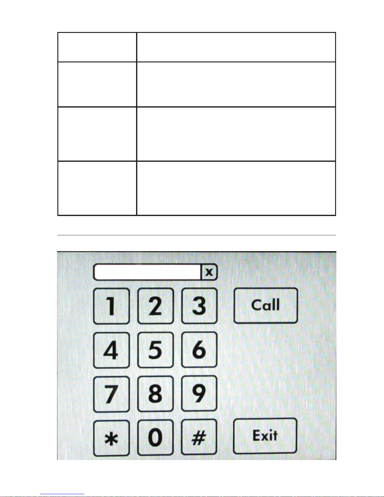
Dialer page: A dialpad page is
presented, complete with a
Call button
(see “Dialer Page” on page 41). This
allows the user to dial a phone number.
Door Control page: A dialpad page is
presented, similar to the Dialer page
above, except that instead of a
Call
button, it has an Open button. This allows
the user to enter a Door Unlock Code
(see “Page Settings” on page 36).
Do Nothing
Sets the device to ignore any touches to
the screen outside of a button.
Button Settings
Enable /
Disable
Turns the button functionality on or off for
the location indicated.
- 41 -
Button Text
Sets the text to be displayed in the button
location.
Action Type
• Goto
• Call
• Do Nothing
Target Page
This setting is displayed if Action Type is
set to Goto. Sets the page to display after
button is clicked. Dropdown box displays
all available pages.
Dialing
Extension
This setting is displayed if Action Type is
set to
Call. Enter the telephone extension
that should be called when the button is
clicked.
Dialer Page

- 42 -
System
Maintenance

- 43 -
Backup / Restore Configuration
Download
configuration
backup
Creates a backup .tar.gz file of
configuration settings for download. The
configuration backup contains UI settings
and SIP settings.
Reset
configuration to
defaults
Discards current configuration and resets
to original factory settings.
Restore
configuration
backup
To restore configuration settings, point
to an archived configuration .tar.gz file,
then click Upload Archive. The 8036 will
restart with the new settings.
Backup / Restore User Interface
In this section, you can make a backup copy of (archive) all
user interface (UI) files, erase all UI files, or restore the UI
from an archive file.
Download
user interface
Backup
Click Generate UI archive to download
a compressed file (in .tar.gz format)
containing all UI settings and files,
including images and addressbook
text files. Note that the files will have a
folder structure where different files will
be separated into different folders. It is
important to maintain this folder structure
to permit restoring later.
Erase
Click Erase to delete all UI files from
the 8036. Before using this function,
we suggest making a backup first (see
above), just in case!

- 44 -
Restore user
interface
backup
Click Choose file to select a compressed
file containing all user interface images
and text files. Then click Upload archive
to load the file to the 8036.
Once the compressed file is uploaded,
the 8036 automatically extracts the files.
Note that a single file or partial group
of files can also be uploaded, as long
as they maintain the required folder
structure and are zipped in that structure.
The 8036 may take several minutes to
complete the update.
Reboot Reboots the device.
Upgrade to New Firmware
This section allows you to upload a new firmware image
and corresponding checksum to upgrade the device. For
more information, please see “Upgrade 8036 Firmware”
on page 48.
System Log
For Algo Technical Support use only.
Kernel Log
For Algo Technical Support use only.
About
Provides basic product information, Algo contact information,
and credits.

- 45 -
Door Control
Network
8036 SIP
Multimedia
Intercom
8061 SIP
Interface
Module
Door Control
Hardware
The 8036 can provide door control functionality when used
with the optional Algo
8061 SIP Relay
Module.
The 8061 serves as
a bridge between the
8036 and peripheral
hardware such as door
strikes, door sensors,
door bells, etc.
As a door opening
controller, the 8061
can be located in a
secure environment to
prevent tampering by
outside visitors.
The door control feature is
activated by a command
from the answering
telephone keypad, or entry
of the door release code by a visitor.
PoE and Relay Connections on back of 8061 SIP Relay Module

- 46 -
Configuring the 8061
1. Find the IP address of the Algo 8061 using the
Algo locator tool available from the Algo website
(www.algosolutions.com/Locator). This tool displays all
of the Algo devices available on the network, and their
corresponding IP addresses. Note this address down as
you will need it when you configure the 8036 for use
with this device.
2. Point your browser to the above IP address. The 8061
Control Panel will be displayed.
3. Log in. The default password is algo
4. Go to the Config page and set a password in the Door
Control Password field in the Features section. Note
this password down as you will be reusing it when
configuring the 8036 with this device.

- 47 -
Configuring the 8036 with the 8061
1. Open the 8036 web interface Control Panel.
2. Go to Settings>Door Control and, in the Relay Module
Address field, enter the IP address of the 8061 you
determined in the previous section.
3. Enter the Relay Module Password that you set previously
when you configured the 8061.
Note that the Relay Module Password is used solely to
secure the link between the 8036 and the 8061. It is
not the same as the Door Unlock code.
4. Refer to “Door Control” on page 28 for more
configuration options.
Door Control Hardware and Wiring
Typical 8036 / 8061 Door Control Setup
Door Control Disabled
(Premise Alarm Set)
Dry Contact Input
Door
Strike
Power
Supply
Door Open
Sensor
(Optional)
Door
Strike
8036 SIP
Multimedia
Intercom
22 or 24 AWG Alarm
Wire (Typical)
Typical #18 AWG
8061 IP
Relay
Controller
Network
SIP
Server

- 48 -
Appendix
Upgrade 8036 Firmware
Periodically, new firmware for the 8036 is released that either
offers new functionality or addresses problems.
To determine if there is firmware available for the 8036,
please visit www.algosolutions.com/8036
To update the firmware:
1. From the top menu, click on
System>Maintenance>Upgrade to New Firmware
2. For Firmware Image, click on Choose File and select the
8036 firmware image file to upload.
3. For Signature, click on Choose File and select the
checksum file to upload.
4. Click Upgrade.
5. After the upgrade is complete, confirm that the firmware
version has changed (refer to top right of Control Panel).

- 49 -
Soft Reset
A soft reset of your 8036 may be necessary if, for example,
the administrative password has been changed and then
forgotten.
To do a soft reset:
1. Disconnect the network cable from the 8036.
2.
Soft Reset
Touch Area
Press and hold the top middle area1 of the screen until a
confirmation button
displays in the
bottom middle area
with the text
description “Press
here to reset to
factory default.”
3. Press this
confirmation button
within five seconds,
and the unit will
reset itself back
to factory default
settings.
1 On the 640 x 480 pixel screen, this is a rectangle area from 240(x), 40(y) to 400(x),
120(y).

- 50 -
Button Positioning Table
The following table provides the location and sizing of
standard button layouts for 8036 User Interface Screens.
Button Layout Button
Dimensions
(in pixels)
Width x Height
Upper Left
X, Y Button
Position(s)
(in pixels)
Single Button 240 x 160 200,160
2 Buttons 240 x 160 40, 160
360,160
3 Buttons 180 x 120 30,160
230,160
430,160
2 x 2 Buttons 200 x 120 110,120
330,120
110,260
330,260
3 x 2 Buttons 180 x 120 30,100
230,100
430,100
30,240
230,240
430,240

- 51 -
3 x 3 Buttons 180 x 100 30,20
230,20
430,20
30,140
230,140
430,140
30,260
230,260
430,260
The 3 x 3 Buttons layout is similar to 3x3 Full Screen
layout below but has extra space at bottom to allow
the unobstructed use of the Home and Back buttons.
3 x 3 Buttons
Full Screen
180 x 100 30,80
230,80
430,80
30,200
230,200
430,200
30,320
230,320
430,320
Adobe® Photoshop® Templates
To simplify the process of creating graphic screens with
buttons that exactly line up to pre-configured 8036 button
layouts, a set of Photoshop templates is available at
www.algosolutions.com/8036templates
Here you’ll find a link to a ZIP file containing multiple
Photoshop files that provide guides for laying out User
Interface screens for the 8036. Each file contains guides for
placing buttons that corresponds to the 8036’s standard
button configurations.
To use the files, open up the Photoshop file that corresponds
to the button configuration you want to use. Then set
Photoshop to snap to guides (View>Snap To>Guides). Then

- 52 -
use Photoshop’s Rectangle Tool to draw buttons using the
guides. After completing the button graphics, choose the
File>Save for Web and Devices menu and use the PNG-24
preset to create the PNG file for importing into the 8036.

- 53 -
Directory (Addressbook) Text Files
You can upload tab-delimited text files to the 8036 (User
Interface>Page Settings>Upload Image/Addressbook) to
create Directory pages. These Directory pages can then be
used by visitors to make calls to individuals listed in the file.
As an example, here is the contents of a directory file with two
fields, one for “name”, and one for “telephone extension”.
Al Smith 1028
Bob Johnson 2156
John Jones 2345
Paul Phillips 1287
Terry Stevens 1256
Note that each line represents one directory member field
and that a TAB separates each field value. Note also that
empty lines will result in empty lines in the Directory.

- 54 -
To create a tab delimited text file using Microsoft Excel:
1. Open your spreadsheet document go to the Windows/
Office round button menu and choose Save As....
2. Change the “Save as type” or “Format” field to read:
‘Text (Tab delimited)’.
3. Enter a name for the document and click Save.
If you need your Addressbook entries sorted, you
should do this when editing your text file. Note that the
8036 will not sort Addressbook entries.

- 55 -
Working with Compressed Files
Using compressed tar.gz2 files, the 8036 Control Panel allows
you to:
• Create archive files of configuration settings
• Restore configuration settings
• Create archive files of User Interface files and settings
• Restore User Interface files and settings
• Upload one or more new or replacement user interface
files to the 8036
Note that in all instances, existing files on the 8036 will
be overwritten if the uploaded file name is the same.
When uploading a tar.gz file to the 8036, it is important
that all the proper folder structure be maintained such that it
matches what is used on the 8036. Otherwise, the uploaded
files may get placed in a wrong location rendering them
unusable.
The best way to get the folder structure right is to first
download an archive from the 8036, extract it to a folder
on your PC, then observe how the folders are named and
arranged. Then make sure all the updated files are in the
same directories. For example, all of the application images
(e.g. background screens) and Directory / Addressbook files
will be in the apps/uiapp/user/ folder.
For more information on downloading and
restoring configuration files, see “Backup / Restore
Configuration” on page 43. For information on
backing up and restoring user interface files, please see
“Backup / Restore User Interface” on page 43.
2 A tar.gz file is a collection of files packaged into a single file (using TAR) and then
compressed (using GZIP).

- 56 -
Please note that you can give any name to the .tar.gz file.
Once the .tar.gz file is uploaded, the 8036 automatically
extracts the files. To replace a file, upload the .tar.gz file
again with this new file. A single file or partial group of files
can also be uploaded, as long as they maintain the required
folder structure and are compressed in that structure.
Note that large applications with numerous image files may
take several minutes to complete the update.

- 57 -
Specifications
SIP Compliance
RFC3261
Power Input
48 V PoE Class 0 (Max 12.95 W - Idle 3 W)
Physical Connection
RJ45
LCD Display
Active TFT 5.7” (14.5cm) color VGA, 80° viewing, sunlight readable, 1000:1 contrast, and
800 cd/m2 backlight
Codecs Supported
G.711, G.722 audio
H.264 video, JPEG still image
Camera
1/3” (8.5mm) wide VGA CMOS Digital Image
Sensor; Max 742x480 WVGA 60fps; 6.0 x
6.0μm pixel size for low light performance;
110dB dynamic range; WVGA, VGA, QVGA,
CIF, QCIF formats
Image Memory
Optional to 8 GBytes
Touchscreen
Optically bonded projected capacitance, H7
hardness
Presence Detection
Area reflective 80cm range, invisible light beam
Speaker
Wideband 8 W
Microphones
Dual beam forming, wideband
Hands-free
Full-duplex capable, reverting to hands-free half
duplex employing DSP echo cancellation and
noise reduction for reliable communication in
difficult outdoor environments
Programmability
Web interface option configuration, or custom
applications using QT based QML script
Environmental
IP64 weather resistant; Ambient temperature:
-30 to +60° C (-22 to 140° F)
Compliance
FCC, CSA/UL, CE
Door/Gate Control
Separate module SIP end point for physical
security, sensing inputs, and third party equipment interfaces

- 58 -
Dimensions
Height: 10-3/4” (27.3 cm)
Width: 7” (17.8 cm)
Depth: 3” (7.6 cm)
In the interests of continuing product improvement, specifications
are subject to change without notice.
For more in-depth information on the 8036, including
application notes and FAQ, please visit
www.algosolutions.com/8036

- 59 -
FCC Compliance
This equipment has been tested and found to comply with the limits for a Class A digital
device, pursuant to part 15 of the FCC Rules. These limits are designed to provide
reasonable protection against interference in a residential installation. This equipment
generates, uses, and can radiate radio frequency energy and, if not installed and
used in accordance with the instructions, may cause harmful interference to radio
communications. However, there is no guarantee that interference will not occur in
a particular installation. If this equipment does cause harmful interference to radio or
television reception, which can be determined by turning the equipment off and on,
the user is encouraged to try to correct the interference by one or more of the following
measures: 1) Reorient or relocate the receiving antenna, 2) Increase the separation
between the equipment and receiver, 3) Connect the equipment into an outlet on a
circuit different from that to which the receiver is connected, or 4) Consult the dealer or
an experienced radio/TV technician for help.
Important Safety Notice
The 8036 SIP Multimedia Intercom is designed and tested to
comply with EN 60950-1:2006 safety requirements. When
the unit is connected to wiring that exits the building, there
is potential risk of lightning induced electrical surges or high
voltages from fault conditions.
To reduce risk, outdoor wiring should be protected by Earth
grounded conduit whenever possible. The 8036 is a Power
over Ethernet (PoE) device. The PoE power source must be a
Limited Power Source (LPS), provided by CAT5 UTP cable, and
isolated from mains by minimum reinforced or double insulation.
Ensure that the PoE injector or PoE enabled switch carries safety
regulatory approval marks (ie CSA, UL, CE).
Algo Communication Products Ltd.
4500 Beedie Street
Burnaby, BC Canada V5J 5L2
www.algosolutions.com
 Loading...