

Page 1
Manual
Version-E150528
Page 2

Manual
Speaker System BANG
Page 2
Important Information
General
Before using your ALGE-TIMIN G device read the complete manual caref ully. It is part of the device and
contains important information about installation, saf ety an d its inten ded us e. T his manual c annot cover all conceivable applicati o ns . For f ur ther inf ormation or in case of problems that are m entioned n ot at
all or not sufficiently detail ed, please contact your ALGE-TIMING representative. You can find c ontact
details on our homepage
www.alge-timing.com
Safety
Apart from the infor mation of this m anual a ll genera l saf ety and acc ident pre vention re gulations of the
legislator must be tak en into account. The device m ust only be used b y trained persons. T he settingup and installation must only be executed according to the manufacturer’s data.
Never adjust t he active speak er system to a very high volum e. Permanent high volum es may damage
your hearing! The hum an ear will get accus tomed to high volumes which do not s eem to be th at high
after some time. Therefore, do not further increase a high volume after getting used to it.
Intended Use
The device must only be us ed for its intended applications. Technic al modifications and any misuse
are prohibited because of t he risk s invo lved! ALGE -TIMING is not liable for damages that are c aused by
improper use or incorrect operation.
Power supply
The stated voltage on the type plate must correspond to vo ltage of the power sour ce. Check all connections and plugs befor e usage. D am aged connecti on wir es m ust be replaced immediately by an authorized electrician. The de vice must only be connected to an electric suppl y that has been installed
by an electrician accord ing to IEC 60364-1 . Never touch the m ains plug with wet hands! Never touc h
live parts!
Cleaning
Please clean the outsid e of the de v ice on ly with a smooth cloth. Detergents c an c aus e damage. Never
submerge in water, nev er open or cl ean with wet c loth. The cleani ng must not be carried out by hose
or high-pressure (risk of short circuits or other damage).
Liability Limitations
All technical inform ation, data and information for instal lation and operation correspond to t he latest
status at time of printing and are made in all conscience considering our past experience and
knowledge. Inform ation, pictures and descriptio n do not entitle to base an y claims. The manufac turer
is not liable for dam age du e to f ail ure to observe the manual, im pr oper us e, i nc o rr ect repairs , tec hn ic al
modifications, use of unauthorized spare parts . Translations are m ade in all consc ience. We ass ume
no liability for translation mistakes, even if the translation is carried out by us or on our behalf.
Disposal
If a label is placed on the device sho wing a crossed out dus tbin on wheels (s ee drawing), the
European directive 2002/96/EG applies for this device.
Please get informed about the app licable regulations for separate collection of electrical and
electronic waste in your country and do not dispose of the old d evices as household waste.
Correct disposal of old equi pment protects the environment and humans against negative conconsequences!
Copyright by
ALGE-TIMING
GmbH
All rights reserved. An y duplication, either in full or in part, req uires the prior written consent of the
copyright holder.
Page 3

Manual
Speaker System BANG
Page 3
Declaration of Conformity
We hereby declare that the following product complies with the below stated st andards. All
components used by us are CE certified by their producer and are not modified by ALGE-
TIMING GmbH.
We, ALGE-TIMING GmbH
Rotkreuzstrasse 39
A-6890 Lustenau
declare in sole responsibility that the electronic start device
BANG
complies with the following standards/normative documents and in case of intended use
complies with the basic requirements of R&TTE 1999/5/EC:
Telecommunication (TC)terminal device
Applied harmonized standards…
EN 60065:2006
EN 60950-1:2006+A11:2009+A1:2010+A12:2011
EN 61000-3-2+A1+A2
EN 61000-6-4:2007
EN 61000-3-3:2013
EN 61000-6-3:2007/A1:2011/AC:2012
EN 61000-6-1:2007
EN 61000-6-2:2005
EN 55024:2010
EN 300422V1.2.2
EN 301489-1V1.8.1
EN 301489-9V1.4.1
Additional information:
The product complies with the low voltage directive 73/23/EEC and EMC directive
2004/108EG and carries the CE sign.
Lustenau, 2013-11-12 ALGE-TIMING GmbH
Albert Vetter
(CIO)
Page 4

Manual
Speaker System BANG
Page 4
Table of Contents
1 Operating Elements and Connections ....................................................................... 5
2 General ......................................................................................................................... 6
2.1 Setting up ............................................................................................................. 6
2.2 Audio Connections ................................................................................................ 6
2.2.1 Inputs ............................................................................................................................................... 6
2.2.2 Output LINE OUT ............................................................................................................................ 6
2.2.3 Passive Speaker System ................................................................................................................. 6
2.3 Connections for Timing ......................................................................................... 7
2.4 Accessory ............................................................................................................. 7
2.4.1 Weather P rotection BANG-BAG ...................................................................................................... 7
2.4.2 Tripod BANG-TRI ............................................................................................................................ 7
2.4.3 Headset Micro for BANG ................................................................................................................. 7
2.4.4 BANG SPK ...................................................................................................................................... 7
3 Commissioning ........................................................................................................... 8
4 Operation ..................................................................................................................... 9
4.1 Multifrequency Receiving Unit for Headset Micro BANG-HS ................................. 9
5 Power Supply ............................................................................................................ 10
5.1 Mains .................................................................................................................. 10
5.2 Rechargeable Battery ......................................................................................... 10
5.2.1 Battery Operating Time .................................................................................................................. 10
5.2.2 Charging Battery ............................................................................................................................ 10
6 Functions ................................................................................................................... 11
6.1 Start Unit SU2 or SU3 ......................................................................................... 12
6.2 Speech Amplifier SV4-S or SV4/SM ................................................................... 12
7 Technical Specifications ........................................................................................... 13
7.1 Amplifier and Speaker ........................................................................................ 13
7.2 Connections for Timing ....................................................................................... 13
7.3 Radio Receiver for Headset Micro BANG-HS ..................................................... 13
Page 5
Manual
Speaker System BANG
Page 5
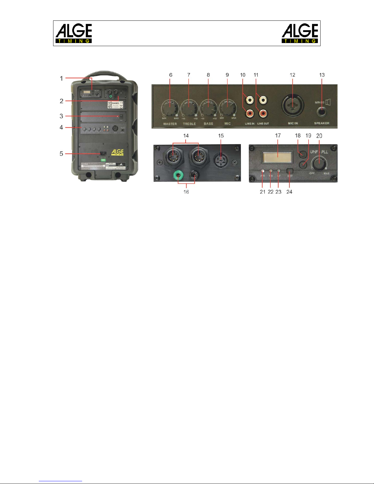
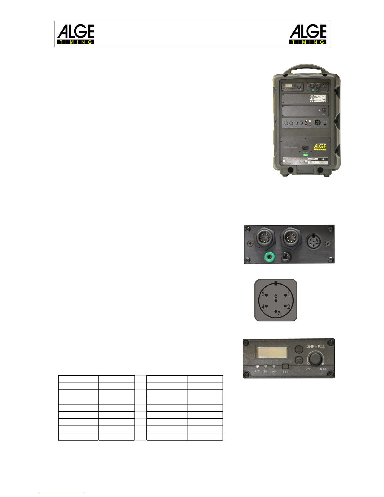
1 Operating Elements and Connections
1 .......... UHF-PLL radio receiver for Headset micro BANG-HS
2 .......... Connections for timing
3 .......... On-off switch
4 .......... Amplifier controller und amplifier connections
5 .......... Mains (90 - 230 V~ / 47 – 63 Hz)
6 .......... Control MASTER for the master volume of the active speaker system
7 .......... Tone controls TREBLE for the mixed signal
8 .......... Tone controls BASS for the mixed signal
9 ......... Volume control for the microphone at the input MIC IN (11)
10 ........ Input LIN E IN (phono jacks) for a stereo audio source with line o utput level, e. g. CD player,
cassette recorder
11 ........ Output LIN E OUT (phono j acks ) for passing on the m ix ed signal, e. g. to a r ecord er or another
active speaker system.
Note: The adj ustments of the tone c ontrols (7) aff ect the LINE OUT s ignal; the adj ustment of
the control MASTER (6), however, does not affect it.
12 ........ Input MIC IN (combined 6.3mm/XLR jack, bal.) for connecting a microphone).
13 ........ 6.3 m m jack SPEAKER for c onnecting an additional passive spe aker system (minimum im-
pedance 8Ω)
14 ........ 2 x LTW-jack to connect at the t iming de vices or f urther speak ers ( e.g. BAN G, Star t Unit SU2 ,
Start Unit SU3, FLASH, TimeMaster)
15 ........ DIN-jack to connect starting devices (e.g. e-Start or start microphone SM8)
16 ........ Banana jacks (green and black) for the start line connection with the timing device
(closing contact, ope n collector)
17 ........ Displ a y to indicate the tr an sm is s ion channel or the rad io freque ncy
18/19 ... Arrow keys:
• to adjus t the c hanne l in the adjustin g m ode: k ey
▲ for channel selec tion “ upward ”; k e y ▼
for channel selection “downward”
• to shor t l y indic at e th e r ad io f requency instead of the channel on displa y (21) for as long as
the key
▲ or ▼ is kept pressed
20 ........ On-off switch and volume control
21 ........ Dive rsit y LED A/B: sho ws red or green to indicate which of the tw o int erna l rec ept i on ant enn as
A or B is presently active
22 ........ Recept ion LE D RX: l ights up when the transm itter is switc hed on and s et to t he r adio fr equen-
cy of the receiver
23 ........ LED AF for the audio signal received: lights up when an audio signal is received
24 ........ Button S ET to call the adjusting m ode f or t he transmission channel an d t o c onf ir m the channel
selection
Page 6

Manual
Speaker System BANG
Page 6
2 General
ALGE-TIMING offers two different models of the active box (speaker-amplifier system) BANG:
BANG ........... wired speaker system
BANG W ....... radio speaker system
In this manual the model BANG is described. The model BANG W has a separate manual.
2.1 S et t ing up
The BANG is suitable for indoor use only. Protect it against dripping water and splash water,
high air humidity, and heat (admissible ambient temperature range 0 – 40 °C).
The BANG can be setup free or on the ALGE tripod BANG-TRI. When using it outdoors it
must be protected against rain or snow with the rain protection BANG-BAG. The rain protection must remain on the BANG during operating.
This active speaker system BANG is a combination of a 2-way speaker system and an amplifier with connections for a microphone and an audio unit with line output level, e. g. CD player or cassette recorder.
The BANG can be integrated in a timing system in order to create a simulated start gun
sound or start tone. Additionally, it can acoustically output a false start tone.
The unit can either be operated from the mains or via the internal rechargeable lead gel batteries to be charged with the integrated charging part. Thus, the speaker system is ideally
suited for mobile applications like sport events. It has a multi -freq uency receiving unit operating with diversity technique* in the UHF range of 863.1 – 864.9 MHz. The frequency range is
divided into 16 channels to be selected as desired.
2.2 Audio Connections
2.2.1 Inputs
A microphone and a stereo unit with line output level (e. g. CD player, DVD player, cassette
recorder or MD recorder) may be connected as audio sources:
• Connect the microphone either via XLR plug or 6.3 mm plug to the balanced jack MIC
IN (12).
• Connect the stereo unit with line output to the phono jacks LINE IN (10).
2.2.2 Output LINE OUT
The phono jacks LINE OUT (11) allow e. g. connection of a recorder or another active
speaker system for PA application. At both jacks t he mixed mono signal of the speaker sy stem is available. The control MASTER (6) for the master volume of the active speaker system does not affect the signal at the output LINE OUT; the adjustments of t he tone controls
TREBLE (7) and BASS (8).
Note: The BANG is not provided with a volume control for the unit at the input LINE IN (10);
i.e. the signal of the unit is always fed to the output LINE OUT at its input volume.
2.2.3 Passive Speaker System
If a speaker system (without amplifier) is additionally required for PA applications, it may be
connected to the jack SPEAKER (13). The minimum impedance of the speaker system must
be 8Ω. ALGE-TIMING offers the passive speakers BANG SPK as accessory for the BANG.
You can connect on one BANG up to eight BANG SPK.
Page 7
Manual
Speaker System BANG
Page 7
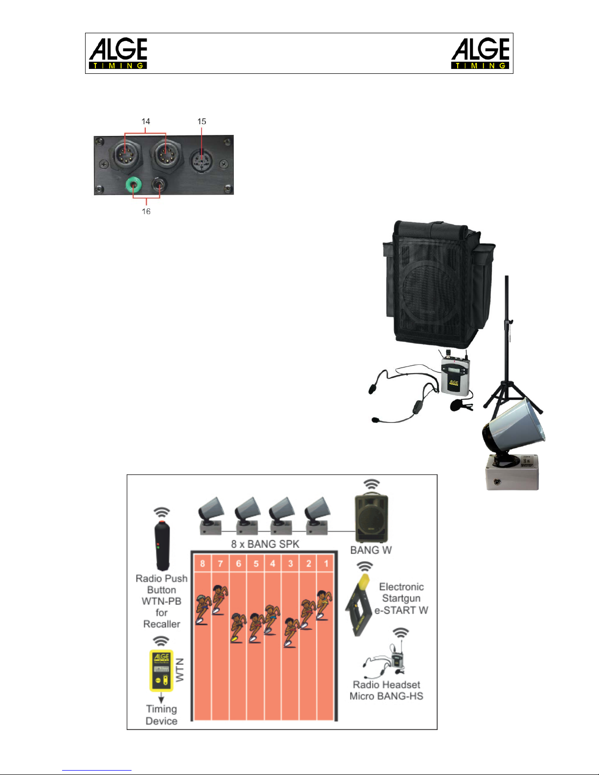
2.3 Connec t ions for Timing
The BANG is connected with the timing system.
14 ...... 2 x LTW-jack to connect at the timing devices or further
speakers (e.g. BANG, Start Unit SU2, Start Unit SU3,
FLASH, TimeMaster)
15 ...... DIN-jack to connect starting devices (e.g. e-Start or start
microphone SM8)
16 ...... Banana jacks (green and black ) for the start line connec-
tion with the timing device
(closing contact, open collector)
2.4 Accessory
ALGE-TIMING offers the following accessory for the BANG:
2.4.1 Weather Protection BANG-BAG
The BANG is made for indoor use. For outdoor use of the
BANG when it rains or snows the BANG needs a protection.
2.4.2 Tripod BANG-TRI
The BANG can be mounted on a tripod, when it should not
be on the floor.
2.4.3 Headset Micro for BANG
With the headset micro BANG-HS it is possible to give
commands to the athletes by radio (wireless connection).
2.4.4 BANG SPK
The passive speaker BANG SPK can be connected at the
BANG (it is possible to connect a maximum of eight BANG SPK). It consists of a
passive horn speaker with an output line of about 10 W. It has a f ixed cable of 12 m
(connection at BANG or BANG SPK and a speaker jack (RCA)) to connect additional
BANG SPK.
Page 8
Manual
Speaker System BANG
Page 8
3 Commissioning
Prior to switching on, turn back the control MASTER (6) for the master volume to MIN first,
and then switch on the speaker system with the switch POWER (3). The switch lights up during operation. If it starts flashing during rechargeable battery operation, the batteries are almost discharged and should be recharged.
To prevent damage to the rechargeable batteries by deep discharge during battery operation, a discharge protection automatically switches off the unit at t he right time. However, due
to self-discharge of the batteries, a deep discharge may also occur when the unit is not operated for a longer period of time. Therefore, always observe the notes in the chapter 5. Power
Supply.
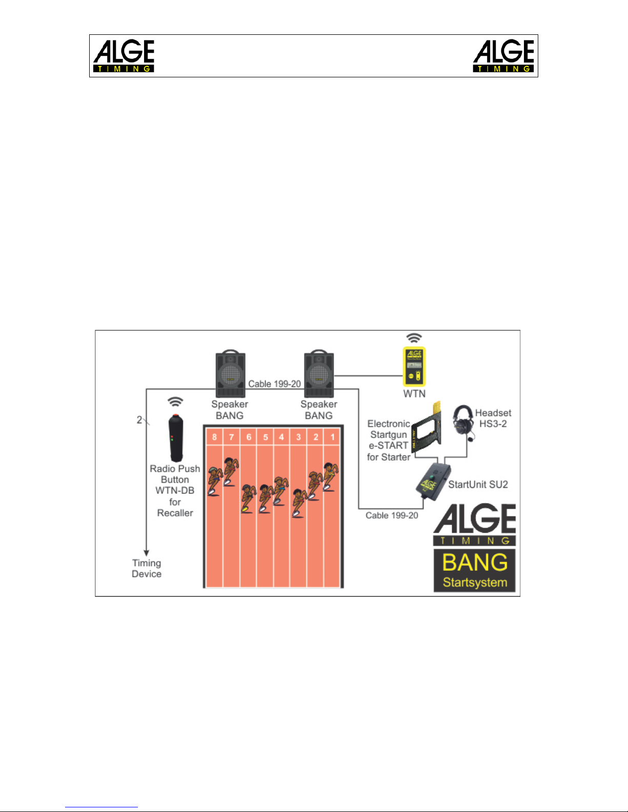
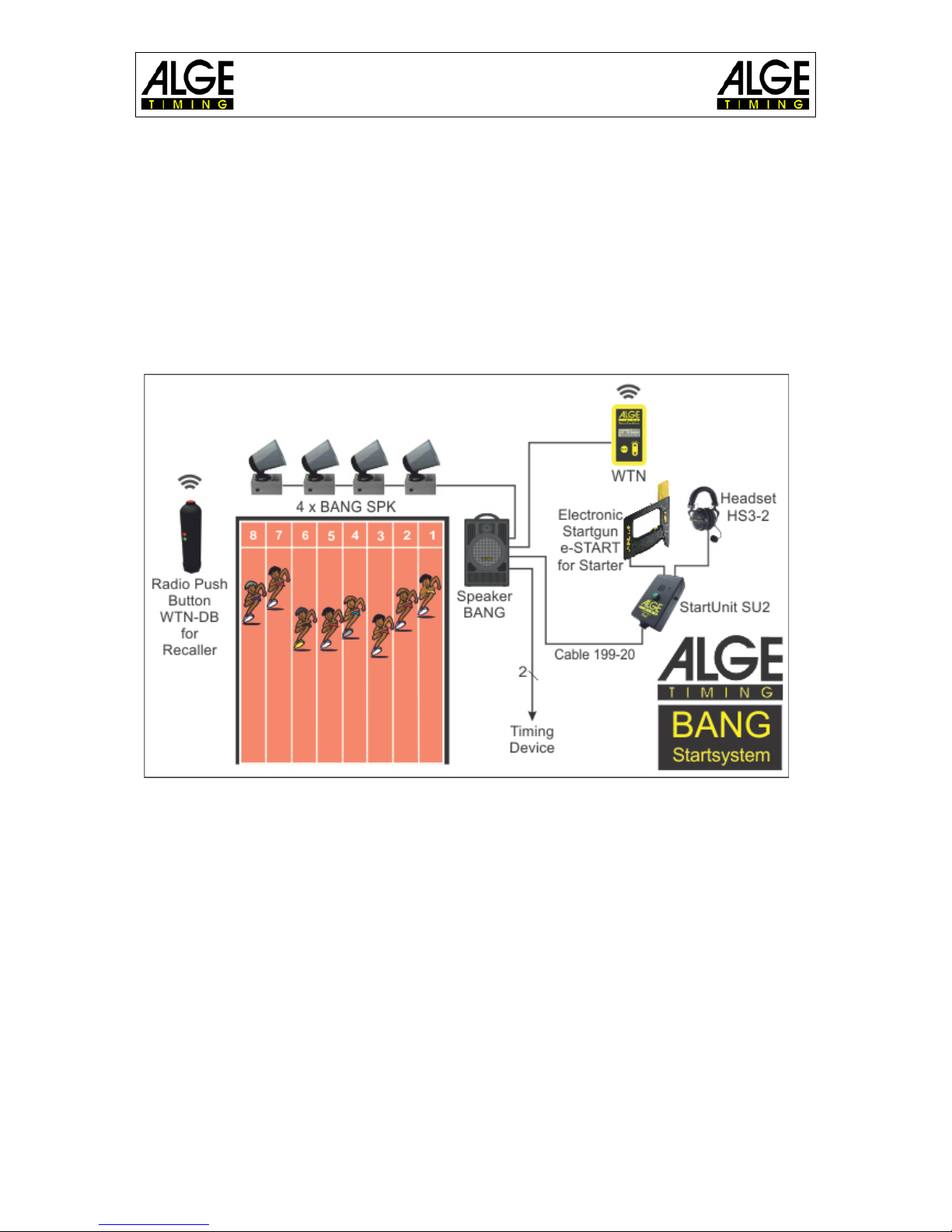
The BANG can be integrated with different devices from ALGE-TIMING as a start system:
• Electronic start gun e-Start
• Start microphone SM8 with speech amplifier SV4/SM and headset HS3-2
• Start Unit SU2
• Start Unit SU3
• BANG SPK
• Wireless Timing Network WTN
Page 9

Manual
Speaker System BANG
Page 9
4 Operation
• Advance the control MASTER (6) for the master volume to such an extent that the subsequent adjustments can be heard well via the speakers.
• Switch on the desired signal sources and mix their signals with the corresponding volume controls or fade them in and out as required (always completely turn back the controls of the signal sources not used):
• for the receiving unit/units (1): on-off switch and volume control (20)
→ 4.1 Multifrequency Receiving Unit for Headset micro BANG-HS
• for the microphone at the input MIC IN (12): volume control MIC (9)
The input LINE IN (10) is not provided with an individual volume control; the volume of
the signal source connected to this input can only be adjusted via the control MASTER
(6) for the master volume.
• With the controls BASS (8) and TREBLE (7) optimize the sound of the mixed signal.
• With the control MASTER (6), adjust the final level for t he master volume of the active
speaker system, and then readjust the sound adjustments, if required.
• After operation, set the switch POWER (3) to the “off” position.
4.1 Multifrequency Receiving Unit for Headset Micro BANG-HS
• To switch on the receiving unit, advance the on-off switch and volume cont rol (20) from
the position OFF. The LED A/B (21) shows r ed or green depending on the receiving antenna A or B currently active.
• Leave the transmitter switched off for the time being. First set the receiving unit to a
transmission channel which is free and interference-free:
• Press button SET (24). The channel indication on the display (17) starts flashing.
• As long as the channel indication keeps flashing (for approx. 10 seconds), the chan-
nel can be selected with the keys ▲ (18) and ▼ (19): key ▲ (18) for channel selec-
tion “upward”; key ▼ (19) for channel selection “downward”.
• Confirm the channel selection with the button SET. (If the selection is not confirmed
within 10 seconds, the unit returns t o the channel previously adjusted.) If the LED RX
(22) lights up after channel selection when the transmitter is switched off, interfering
signals or signals of other transmitters are received on this channel. I n this case, adjust the receiving unit to a different channel.
• It is possible to shortly show the radio frequency for the channel adjusted: as long as the
key ▲ (18) or ▼ (19) is kept pressed, the display shows the frequency instead of the
channel.
• If the transmitter is switched on and set to the same channel as the receiving unit, the
LED RX (22) light s up to indicate reception of a radio signal. The LED AF (23) lights up if
the transmitter transmits an audio signal of sufficient level on the radio f requency adjusted.
• Adjust the desired volume for the audio signal received with the control (20).
Page 10

Manual
Speaker System BANG
Page 10
5 Power Supply
The BANG can be use connected to the mains or running on the internal rechargeable batteries.
5.1 Mains
To operate the active speaker system via a mains socket and/or to recharge the internal lead
gel batteries, connect the mains cable provided to the mains jack (5) and to a mains s ocket
(90 - 230 V~ / 47 – 63 Hz / 150 VA).
Mains: (90 - 230 V~ / 47 – 63 Hz / 150 VA)
5.2 Rechargeable Battery
The BANG has two built-in lead gel batteries (each 12 V /3 Ah) for a mains independent use.
5.2.1 Battery Operating Time
The running time of the BANG using the internal batteries depends on the volume and the
duration of active use (volume output).
Operating Time: about 3 to 4 hours at normal use
5.2.2 Charging Battery
When the active speaker system is connected to the mains, the automatic charging f or the
rechargeable batteries is always active. The LED CHARGE lights up:
Red: the batteries are being charged
Green: the batteries have been fully charged
For charging, it is not be necessary to switch on the speaker system with the POWER switch
(5); however, it can be operated as usual during the charging process.
The charge control circuit prevents overcharge of the batteries; it is recommended, however,
to disconnect the mains plug from the socket after charging if the unit is not used for a longer
period of time.
Important!
To prevent damage to the batteries by deep discharge and to prevent a reduction of their durability, please observe the following notes:
• Always fully recharge the batteries prior to initial operation and after longer storage.
• If the POWER switch starts flashing during battery operation, the batteries are almost
discharged and should be recharged as soon as possible.
• Fully recharge the batteries prior to longer storage and at least every 2 months during
storage.
Page 11
Manual
Speaker System BANG
Page 11
6 Functions
If you receive a start impulse at the BANG from a device that is connect ed to one of the t wo
identical LTW-jacks (14) or to the DIN jack (15) you get a start sound output.
The start sound can be adjusted from the producer (ALGE-TIMING) as „gun sound“ or „horn
sound“. The start sound cannot be adjusted by the operator (the BANG needs a different
software).
The BANG outputs a start impulse to trigger a timing device (closing contact) via t he green
and black banana socket (16).
If the BANG receives another start impulse within 5 seconds of the first start impulse it outputs a false start sound (several honks within a short time).
Page 12
Manual
Speaker System BANG
Page 12
6.1 S t a rt Unit SU2 or SU3
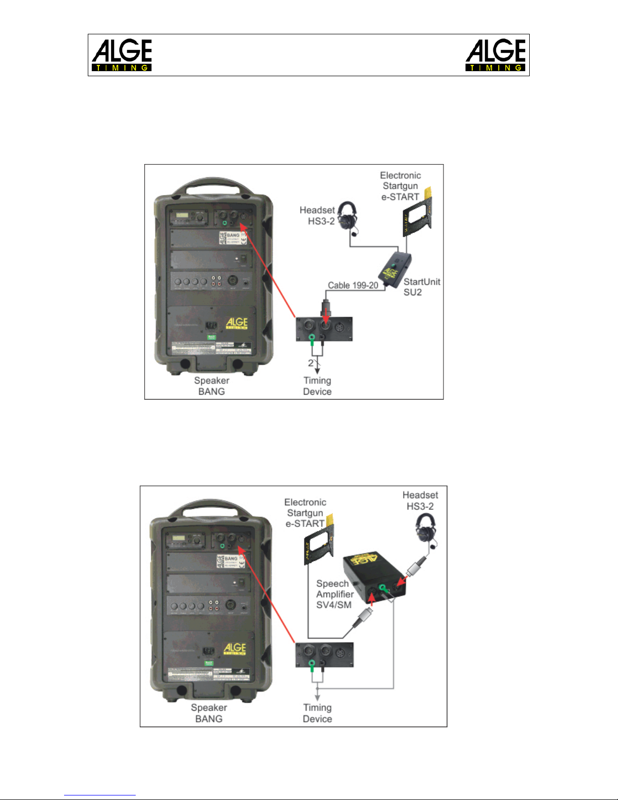
The Start Unit SU2 or SU3 can be connected at one of the two LTW jacks (14) with cable
199-xx. With the built-in microphone of the start unit you can give oral commands to the athletes through the BANG. Further, you can connect a headset to communicate with the timing
operator.
6.2 Speech Amplifier SV4-S or SV4/SM
You can connect a speech amplifier with headset at the banana socket (16) to communicate
with the timing operator. Connect a two wire cable parallel at the banana socket t o the timing
device (start impulse).
Page 13
Manual
Speaker System BANG
Page 13
7 Technical Specifications
7.1 Amplifier and Speaker
Amplifier Power: 80WMAX/50WRMS
Frequency Range: 70 – 16 000 Hz
Speaker System: 20 cm (8″) bass speaker and 2.5 cm (1″) tweeter
Input MIC IN Sensitivity: 6 mV
Connection: XLR/6,3-mm-Klinke, sym.
Input LINE IN Sensitivity: 800mV
Connection: phono jack
Output LINE OUT Level: 1 V
Connection: phono jack
Output SPEAKER: 6.3 mm jack for a passive speaker system
(minimum impedance 8Ω)
Tone Controls: Treble: ±15 dB/100 Hz
Bass: ±10 dB/10 kHz
Ambient Temperature: 0 to 40°C (32 to 104 F)
Power Supply: via the mains voltage (230 V~/50Hz/150 VA) or
the internal rechargeable lead gel batteries (2 × 12 V /3 Ah)
Operating Time: with internal battery about four hours
Dimensions: 300 × 470 × 230 mm (W × H × D)
Weight: ca. 11.2 kg
7.2 Connec t ions for Timing
2 x LTW jack: Connection with start devices or further
speakers e.g. BANG, SU2, SU3, FLASH
1 x DIN jack: Connection with start devices
e.g. e-Start or start microphone SM8
1 x Banana Socket (green – black): Start output signal, normally
closed contact, open collector)
DIN jack: 1 .......... timing channel C0 (start input)
2 .......... status
3 .......... ground
4 .......... power supply output (+10 VDC
out)
5 .......... empty
6 .......... empty
7.3 Radio Receiver for Headset Micro BANG-HS
Receiving Unit: PLL- multifrequency receiver in diversity
technique
Range: ca. 30 m
Radio Frequency: 863.1 – 864.9 MHz, divided into 16 channels
Channel CH Frequency Channel CH Frequency
1 863.1 MHz 9 863.2 MHz
2 864.1 MHz 10 864.2 MHz
3 863.6 MHz 11 863.7 MHz
4 864.6 MHz 12 864.7 MHz
5 863.3 MHz 13 863.4 MHz
6 864.3 MHz 14 864.4 MHz
7 863.8 MHz 15 863.9 MHz
8 864.8 MHz 16 864.9 MHz
Page 14
Manual
Speaker System BANG
Page 14
8 Special Settings
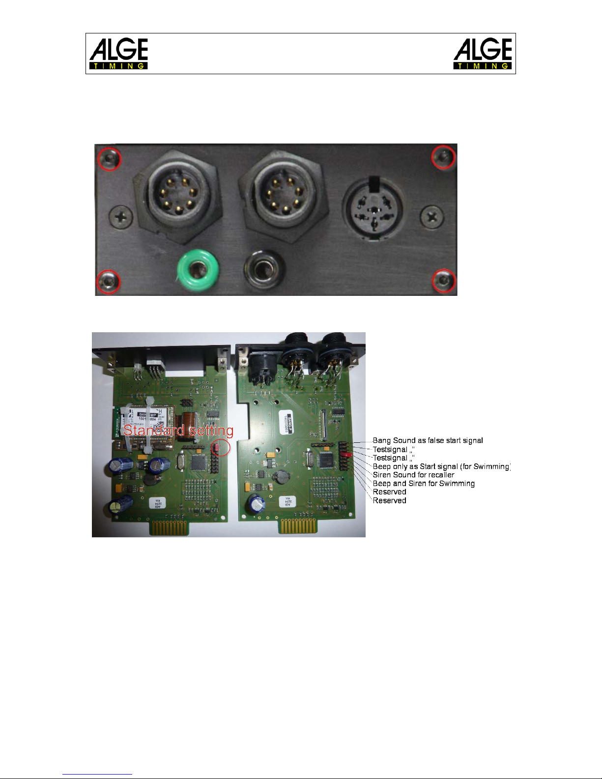
For various sports and applications it can be necessary to change a setting of the Bang. First
you have to switch off the Bang. Open the red marked screws.
When the screws are removed, you can pull out the unit.
Now you can change the setting with the red jumper:
After finishing the setting plug the unit in the Bang again. After t hat you have to fix the screws
again.
Hint:
The Settings „Beep as Start signal” and „Siren Sound“ are available since March 2015.
The Settings „Beep and Siren for Swimming” are available since May 2015.
Page 15

Manual
Speaker System BANG
Page 15
Page 16

Manual
Speaker System BANG
Page 16
Subject to changes
Copyright by
ALGE-TIMING GmbH
Rotkreuzstr. 39
6890 Lustenau / Austria
www.alge-timing.com
 Loading...