

Page 1
|enue|/\|
oo
doqs>|4O/\/\
06W-D oo
09€I-
9831.°
oo
98U
^861-
01 fe£6l
Page 2
Alfasud
by J H Haynes
Member of the Guild of Motoring Writers
and Tim Parker
Models covered
Alfa Romeo Alfasud Saloon, Hatchback and Sprint Coupe models
(including Veloce)
1186
cc,
1286
cc,
1350
cc and
1490
cc
ISBN 0 85696 974 5
© Haynes Publishing Group 1977, 1984
All rights reserved. No part of this book may be reproduced or transmitted in
any form or by any means, electronic or mechanical, including photocopying,
recording or by any information storage or retrieval system, without permission
in writing from the copyright holder.
Printed in England
HAYNES PUBLISHING GROUP
SPARKFORD YEOVIL
SOMERSET BA22 7JJ ENGLAND
HAYNES PUBLICATIONS INC
861 LAWRENCE
NEWBURYPARK
CALIFORNIA
(292-
12K2)
DRIVE
91320 USA
Page 3
Acknowledgements
Thanks are due to Alfa Romeo (GB) Limited for the provision of
technical information and for the use of certain illustrations. The
Champion Sparking Plug Company supplied the illustrations showing
the various spark plug conditions, and Sykes-Pickavant Ltd provided
some of the workshop tools.
About this manual
Its
aim
The aim of this manual is to help you get the best value from your
vehicle. It can do so in several ways. It can help you decide what work
must be done (even should you choose to get it done by a garage),
provide information on routine maintenance and servicing, and give a
logical course of action and diagnosis when random faults occur.
However, it is hoped that you will use the manual by tackling the work
yourself. On simpler jobs it may even be quicker than booking the car
into a garage and going there twice, to leave and collect it. Perhaps
most important, a lot of money can be saved by avoiding the costs a
garage must charge to cover its labour and overheads.
The manual has drawings and descriptions to show the function of
the various components so that their layout can be
the tasks are described and photographed in a step-by-step sequence
so that even a novice can do the work.
Its
arrangement
The manual is divided into twelve Chapters, each covering a logical
sub-division of the vehicle. The Chapters are each divided into Sections,
numbered with single figures, eg 5; and the Sections into paragraphs
(or
sub-sections)
they are in, eg
with decimal numbers following on from the Section
5.1,
5.2, 5.3 etc.
understood.
Then
Special thanks are due to Ron Petheram of Alfacenta, Turgis Green,
near Basingstoke, for much useful information required when updating
the manual. Willshires of Salisbury provided a late model car for
workshop photographic purposes.
It is freely illustrated, especially in those parts where there is a
detailed sequence of operations to be carried out. There are two forms
of illustration: figures and photographs. The
sequence with decimal numbers, according to their position in the
Chapter — eg Fig. 6.4 is the fourth drawing/illustration in Chapter 6.
Photographs carry the same number (either individually or in related
groups) as the Section or sub-section to which they relate.
There is an alphabetical index at the back of the manual as well as
a contents list at the front. Each Chapter is also preceded by its own
individual contents list.
References
a person in the driver's seat facing forwards.
Unless otherwise stated, nuts and bolts are removed by turning
anti-clockwise, and tightened by turning clockwise.
Vehicle manufacturers continually make changes to specifications
and recommendations, and these, when
our manuals at the earliest opportunity.
Whilst every care is taken to ensure that the information in this
manual is correct, no liability can be accepted by the authors or
publishers for loss, damage or injury caused by any errors in, or
omissions
to the
'left'
from,
the information given.
or
'right'
of the
notified,
figures
are numbered in
vehicle
are in the
are incorporated into
sense
of
Introduction to the Alfasud
Introduced in Italy in mid-1972, and in the UK in 1974, the Alfasud
was designed to provide a small car in the Alfa Romeo range. A factory
specifically for the production of the model was built near Naples in
Southern Italy (hence the -sud). Mechanical design of the car was by
Rudolf
Hruschka,
by Giugiaro of Italdesign. The result was a distinctively Italian-looking
car, driven at the front wheels by a water-cooled flat four engine. The
car's handling proved to be superb, setting new standards for vehicles
in its class, and its combination of performance with reasonable price
won it many friends.
Mechanical changes to the Alfasud have been few, consisting mostly
of increasing engine capacity and (on Veloce models) the fitting of
formerly of
Porsche,
while the body was designed
twin carburettors. Body styles available in the UK have been two-door
and four-door saloons and hatchbacks, and the distinctive Coupe style
of the Sprint. An Estate model, available in the rest of Europe, was
regrettably never imported to the
With
productio'n
the initial design may be judged by the continuation of the major
mechanical components in other Alfa Romeo models. The
mechanic may curse some of the more idiosyncratic features of the
original design, but there is no doubt that the Alfasud provides high
performance motoring on a moderate budget, and for this reason alone
it will surely be around for a long time.
of the Alfasud set to finish in
UK.
1984,
the success of
DIY
Page 4
Contents
Page
Acknowledgements
About this manual
Introduction to the Alfasud
Buying spare parts and vehicle identification numbers
Tools and working facilities
Routine maintenance
Safety first!
General data
Jacking and towing
Recommended lubricants and fluids
Chapter 1 Engine
Chapter 2 Cooling and heating systems
Chapter 3
Carburation;
fuel and exhaust systems
2
2
2
5
6
8
10
11
11
12
13
39
45
Chapter 4 Ignition system
Chapter 5 Clutch
Chapter 6 Gearbox and final drive
Chapter 7 Driveshafts, hubs, wheels and tyres
Chapter 8 Braking system
Chapter 9 Electrical system
Chapter
10
Suspension and steering
Chapter
1 1
Bodywork and
Chapter
12
Supplement: Revisions and information on later models
Fault diagnosis
General repair procedures
Conversion factors
Index
fittings
54
61
66
80
83
92
110
120
130
164
167
168
169
Page 5
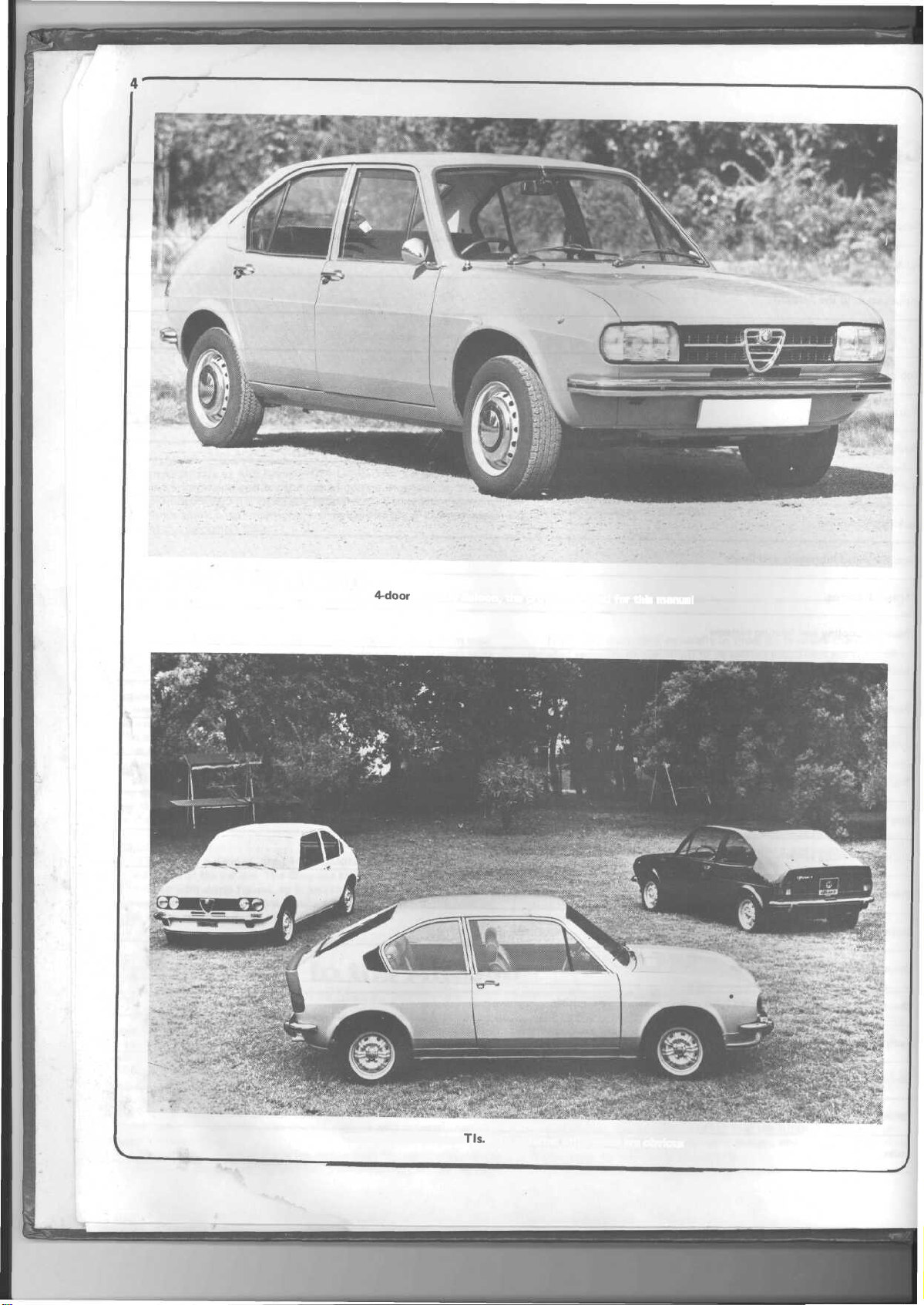
1973
4-door
Alfasud Saloon, the project car used for this manual
1975 group of Alfasud
TIs.
The external differences are obvious
Page 6
Buying spare parts
and vehicle identification numbers
Buying spare parts
Spare parts are available from many sources, for example: Alfa
Romeo garages, other garages and accessory shops, and motor factors.
Our advice regarding spare part sources is as follows:
Officially appointed Alfa Romeo garages - This is the best source of
parts which are peculiar to your vehicle and are otherwise not generally
available (eg complete cylinder heads, internal gearbox components,
badges, interior trim etc). It is also the only place at which you should
buy parts if your car is still under warranty - non - Alfa Romeo
components may invalidate the warranty. To be sure of obtaining the
correct parts it will always be necessary to give the storeman your car's
engine and chassis number, and if possible, to take the
for positive identification. Remember that many parts are available on
a factory exchange scheme - any parts returned should always be clean!
It obviously makes good sense to go straight to the specialists on your
car for this type of part for they are best equipped to supply you.
Other garages and accessory shops - These are often very good places
to buy materials and components needed for the maintenance of your
car (eg oil filters, spark plugs, bulbs, fan belts, oils and greases, touch-up
paint,
filler paste etc). They also sell general accessories, usually have
convenient opening hours, charge lower prices and can often be found
not far from home.
Motor factors - Good factors will stock all of the more important
components which wear out relatively quickly (eg clutch components,
pistons, valves, exhaust system, brake cylinders/pipes/hoses/seals/shoes
and pads
components on a part exchange basis - this can save a considerable
etc).
Motor factors will often provide new or reconditioned
'old'
part along
amount of money.
Gaskets - special note
With gasket sets - for both engine and gearbox - do not be alarmed
if there seem to be many items included in the set you buy, which do
not fit your vehicle. To save a lot of variety of kits they include in one
enough to cover a variety of types over a period of time so you are
certain to have some left over. However, it is a good idea to check the
set before leaving the parts store. Some of the ones you may need
could
be
omitted.
applies to some of the smaller ones.
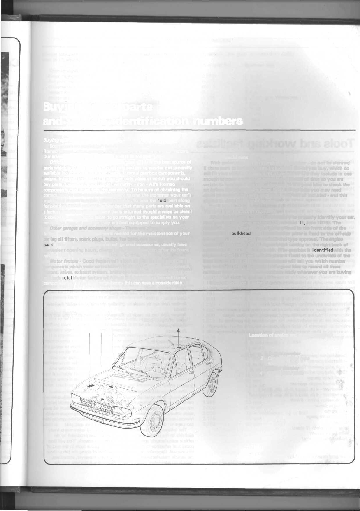
Vehicle identification numbers
When buying spare parts it is necessary to properly identify your car.
First give the car model and date (ie; Alfasud
chassis
number
intermediate
inner wing - this gives the car model and type approval. The engine
number is stamped into the engine block casting on the right bank of
cylinders at the number 3 cylinder. (The gearbox is
engine number). The paint finish plate is fixed to the underside of the
boot lid. It is a foil plate. Commonsense will tell you which number
you want and when. However, it is a good idea to record all these
numbers from your car and have them ready whenever you are buying
new parts.
Note the location illustration.
is
bulkhead.
Oil
seals
particularly
stamped
on a
The Identification plate is fixed to the off-side
are not all
plate affixed
included
Tl,
June 1975). The
to the
front
identified
- and
side
this
of the
with the
2 3 1
Location of engine and chassis numbers
1 Chassis number
2 Car model and type
approval plate
3 Engine number
4 Finish paint plate
Page 7
Tools and
working
facilities
Introduction
A selection of good tools is a fundamental requirement for anyone
contemplating the maintenance and repair of a motor vehicle. For the
owner
who
does
not
possess
any,
their
able
expense,
However, provided that the tools purchased are of good quality, they
will
last
To help the average owner to decide which tools are needed to carry
out the various tasks detailed in this manual, we have compiled three
lists of tools under the following headings: Maintenance and minor
repair, Repair and overhaul, and Special. The newcomer to practical
mechanics should start off with the
kit and confine himself to the simpler jobs around the vehicle. Then, as
his confidence and experience grows, he can undertake more difficult
tasks, buying extra tools as, and when, they are needed. In this way, a
'Maintenance
and
overhaul'
major
good enough for most repair and overhaul procedures and will add tools
from the
amount of use these tools will be put to.
It is obviously not possible to cover the subject of tools fully here.
For those who wish to
book entitled
publishers of this manual.
offsetting some of the savings made by
for
many
years
and
prove
and minor
tool kit over a considerable period of time without any
cash
outlays.
'Special'
'How
repair'
The
experienced do-it-yourselfer
category when he feels the expense is justified by the
learn
to Choose and Use Car Tools' available from the
more about tools and their use there is a
purchase
an
extremely
'Maintenance
tool kit can be built-up into a
will
prove a consider-
doing-it-yourself.
worthwhile
and minor
will
have a tool
investment.
repair'
tool
'Repair
kit
Maintenance and minor repair tool kit
The tools given in this list should be considered as a minimum
requirement if routine
operations are to be undertaken. We recommend the purchase of
combination spanners (ring one end,
more expensive than open-ended ones, they do give the advantages of
both types of spanner.
Combination spanners - 10,
Adjustable
Spark plug spanner (with rubber insert)
Spark
plug
Set of feeler gauges
Brake bleed nipple spanner
Screwdriver - 4 in. long x % in.
Screwdriver - 4 in. long x % in. dia. (crosshead)
Combination pliers - 6 inch
Hacksaw,
Tyre pump
Tyre pressure gauge
Oil can
Fine emery cloth
Wire brush (small)
Funnel (medium size)
maintenance,
spanner - 9 inch
gap adjustment tool
junior
(1
sheet)
servicing and minor repair
open-ended
11,
13, 14,
dia.
(plain)
the other); although
17,30mm
Repair and overhaul tool kit
These tools are virtually essential for anyone undertaking any major
repairs to a motor vehicle, and are additional to those given in the Basic
list. Include in this list is a comprehensive set of sockets. Although
these are expensive they will be found invaluable as they are so
particularly if various drives are included in the set. We recommend the
1
/2 square-drive type, as this can be used with most proprietary torque
wrenches. If you cannot afford a socket set, even bought piecemeal, then
inexpensive tubular box spanners are a useful alternative.
The tools in this list will occasionally need to supplemented by
tools from the Special list.
Sockets (or box spanners) to cover range 6 to 27 mm
Reversible ratchet drive (for use with sockets)
Extension
Universal joint (for use with sockets)
Torque wrench (for use with sockets)
Mole wrench - 8 inch
Ball pein hammer
Soft-faced
ScrewdriverScrewdriverScrewdriverScrewdriverPliers
Pliers - needle nosed
Pliers - circlip
Cold
Scriber
blade)
Scraper (this can be made by flattening and sharpening one end of a
piece of copper pipe)
Centre punch
Pin punch
Hacksaw
Valve grinding tool
Steel
Allen keys
Selection of files
Wire brush (large)
Axle stands
Jack (strong scissor or hydraulic type)
piece,
10
inch (for use with sockets)
hammer, plastic or rubber
6 in.
long x 5/16
2in.
longx
V/ain.
longx % in. dia. (crosshead)
3in.
- electricians side cutters
chisel-
(this can be made by grinding the end of a broken hacksaw
rule/straight
longx
(internal
% inch
edge
in. dia. (plain)
5/16in.
square (plain)
1/8in.
dia. (electricians)
and external)
versatile-
Special tools
The tools in this list are those which are not used regularly, are
expensive to buy, or which need to be used in accordance with their
manufacturers instructions. Unless relatively difficult mechanical jobs
are
undertaken
tools. Where this is the case, you could consider clubbing together with
friends (or a motorists club) to make a joint purchase, or borrowing the
tools against deposit from a local garage or tool hire specialist.
The following list contains only those tools and instruments freely
available to the public, and not those special tools produced by the
vehicle manufacturer specifically for its dealer network. You will find
occasional reference to these manufacturers special tools in the text of
this manual. Generally, an alternative method of doing the job without
the vehicle manufacturers special tool is given. However,
there is no alternative to using them. Where this is the case and the
frequently,
it
will
not be
economic
to buy
many
of
sometimes,
these
Page 8
Tools and working facilities
relevant tool cannot be bought or borrowed you will have to entrust the
work to a franchised garage.
Valve spring compressor
Piston ring compressor
Ball joint separator
Universal hub/bearing puller
Impact
screwdriver
Micrometer and/or vernier gauge
Carburettor flow balancing device (where applicable)
Dial gauge
Stroboscopic
timing
light
Dwell angle meter/tachometer
Universal electrical
multi-meter
Cylinder compression gauge
Lifting tackle
Trolley jack
Light with extension lead
Buying tools
For practically all tools, a tool factor is the best source since he will
have a very comprehensive
range
compared
with
the
average
garage
or
accessory shop. Having said that, accessory shops often offer excellent
quality tools at discount prices, so it pays to shop around.
Remember, you don't have to buy the most expensive items on the
shelf, but it is always advisable to steer clear of the very cheap tools.
There are plenty of good tools around, at reasonable prices, so ask the
proprietor or manager of the shop for advice before making a purchase.
Care
and
maintenance
of
tools
Having purchased a reasonable tool kit, it is necessary to keep the
tools in a clean and serviceable
dirt,
grease
and
metal particles using a clean,
condition,
After use, always wipe off any
dry
cloth,
before
putting
the tools away. Never leave them lying around after they have been
used. A simple
tool
rack
on the
garage
or
workshop
wall,
for
items
such
as screwdrivers and pliers is a good idea. Store all normal spanners
and sockets in a metal box. Any measuring instruments, gauges,
meters,
etc., must be carefully stored where they cannot be damaged or become
rusty.
Take a little
care when
the
tools
are
used. Hammer heads
inevitably
become marked and screwdrivers lose the keen edge on their blades from
time-to-time. A little timely attention with emery cloth or a file will
soon restore items like this to a good serviceable finish.
Working facilities
Not to be forgotten when discussing tools, is the workshop itself. If
anything more than routine maintenance is to be carried out, some form
of suitable working area becomes essential.
It is appreciated that many an owner mechanic is forced by
circumstances to remove the engine or similar
of a garage or workshop. Having done this, any repairs should always
be done under the cover of a roof.
Wherever possible, any dismantling should be done on a clean flat
workbench or table at a suitable working height.
Any workbench needs a vice: one with a jaw opening of 4 in. (100
mm) is suitable for most jobs. As mentioned previously, some clean dry
storage space is also required for tools, as well as the lubricants, cleaning
fluids, touch-up paints and so on which soon become necessary.
Another item which may be required, and which has a much more
general
usage,
is an
electric
drill
with a chuck capacity
(8 mm). This, together with a good range of twist drills, is virtually
essential
for
fitting
accessories
such
as
wing
Last, but not least, always keep a supply of old newspapers and clean,
lint-free rags available, and try to keep any working area as clean as
possible.
item,
mirrors
without the benefit
of at
least 5/16
and
reversing
lights.
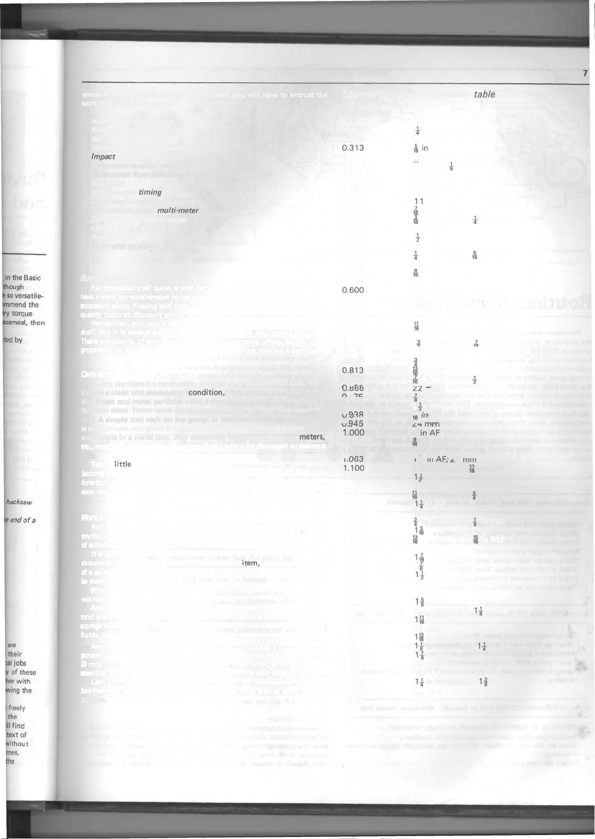
Spanner jaw gap comparison
in.
Jaw gap
0.250
0.276
0.313
0.315
0.344
0.354
0.375
0.394
0.433
0.438
0.445
0.472
0.500
0.512
0.525
0.551
0.563
0.591
0.600
0.625
0.630
0.669
0.686
0.709
0.710
0.748
0.750
0.813
0.820
r\ o c
U.oDD
r\ o ~7
0.875
0.920
o
\J • C7
0
vj.
1
1.010
1.024
1
1.100
1.125
1.181
1.200
1.250
1.260
1.300
1.313
1.390
1.417
1.438
1.480
1.500
1.575
1.614
1.625
1.670
1.688
1.811
1.813
1.860
1.875
1.969
2.000
2.050
2.165
2.362
CHR
945
^M-U
.000
Ofi3
1
,\J\J\J
O O
(in)
Spanner size
|
7 mm
*in
8 mm
32 in AF; £ in Whitworth
9 mm
f in AF
&
^
|
-£
fl
& in Whitworth; f in BSF
ID ' 8
|
ll
i
i
j§
c
c
£
O O
ZZ
|-
|
15
16
O A
^.H-
1
&
26 mm
1— in
| in Whitworth;
1-
30 mm
je
32 mm
-fj§
36 mm
|
40 mm; jf in Whitworth
41 mm
46 mm
50 mm
2 in AF
55 mm
60 mm
table
in
AF
AF
10 mm
1 1
mm
in AF
in Whitworth; £ in BSF
12 mm
in
AF
13 mm
in Whitworth; £ in BSF
14 mm
in AF
1 5 mm
in
AF
16 mm
1 7 mm
in
AF
18 mm
in Whitworth; £ in BSF
8 ' 10
19 mm
in
AF
in AF
in Whitworth; ± in BSF
«-
mm
in AF
in Whitworth; £ in BSF
|n AC
in
Mr
ryi
m
111
1
II
j
p
n
M
in Whitworth; f in BSF
AF'
1
1g
in Whitworth; f in BSF
H
in Whitworth;
1£
in Whitworth;
1£
1I
1|
1 in Whitworth;
1jj
1Ji
1£
1|
H
97 mm
111
r\\ r £. / llllil
j£
in BSF
in AF
in
AF
|-
in BSF
in AF
|f
in BSF
in AF
in Whitworth; 1 in BSF
in AF
in AF
1£
in BSF
in AF
in AF
in Whitworth;
1£
in BSF
in AF
in Whitworth;
1f
in BSF
Page 9
Routine maintenance
Maintenance is essential for ensuring safety and desirable for
the purpose of getting the best in terms of performance and
economy from the car. Over the years the need for periodic
lubrication - oiling, greasing and so on - has been drastically
reduced if not totally eliminated. This has unfortunately tended
to lead some owners to think that because no such action is required
the
items either
delusion. It follows therefore that the largest initial element of
maintenance is visual examination. This may lead to repairs or renewals.
Starting procedure: Starting from cold the Alfasud needs careful
warming up. Once the engine is running carefully coax it. Do not
accelerate the engine until it is warm, since when the engine is cold
the oil cannot reach all points requiring lubrication. A red light
exhibited on the facia will not go out until the oil becomes sufficiently
warm.
Every 250 miles (400
Check engine oil level and top up if necessary
Check coolant level and top up if necessary
Check brake
frequent topping up is required
Check battery electrolyte level (if possible) and top up if necessary
Check windscreen washer
Check tyre pressures (including spare) and tread condition
Check operation of lights, horn, wipers etc
Every 6000 miles
Change engine oil and renew filter
Inspect air filter element; clean or renew as necessary
Inspect spark plugs; clean or renew as necessary
Inspect brake pads; renew as necessary
Inspect braking system flexible hoses and steel pipes; renew as
necessary
Every
12
In addition to, or instead
Check engine valve clearances and adjust if necessary
Check tension and condition of alternator
as necessary
Renew air filter element
no
longer exist
km),
fluid
level
(10
000 miles (20 000 km) or
or
weekly, or before a long journey
and top up if
fluid
000 km) or six months, whichever comes first
of,
the work previously specified
will
last
necessary. Check
level
and top up if
annually,
for
ever.
This
is a
for
necessary
whichever comes first
drivebelt;
adjust or renew
serious
leaks
if
Renew spark plugs
Gap or renew contact breaker points (when applicable)
Check ignition timing
Clean crankcase ventilation hoses and flame trap
Check idle speed and adjust if necessary
Check gearbox oil level and top up if necessary
Check
driveshaft
Check handbrake operation and adjust as necessary
Lubricate hinges, locks, etc
Inspect all systems for leaks, damage, etc
Every 24 000 miles (40 000 km) or annually, whichever comes
Renew brake hydraulic fluid
Every 24 000 miles (40 000 km) or two years, whichever comes first
In addition
Every 36 000 miles (60 000 km) or three years, whichever comes first
In addition
Additionally the following items should be attended to as time can be
spared:
to,
Renew in-line fuel filters (when fitted)
Renew gearbox oil
to,
Renew the alternator drivebelt
Renew the camshaft drivebelts
rubber boots for security and soundness
or instead of, the work previously specified
or instead
of,
the work previously specified
first
Cleaning
Examination
applies to the body of the car, inside and out, in order that deterioration
due to rust or unknown damage may be detected. Certain parts of the
body frame, if rusted badly, can result in the vehicle being declared
unsafe
and it
of
components requires
will
not
pass
the
annual test
that
they
for
roadworthiness.
be
cleaned.
The
same
Exhaust system
An exhaust system must be leakproof, and the noise level below a
certain minimum. Excessive leaks may cause carbon monoxide fumes to
enter the passenger compartment. Excessive noise constitutes a public
nuisance. Both these faults may cause the vehicle to be kept off the
road. Repair or replace defective sections when symptoms are apparent.
Page 10
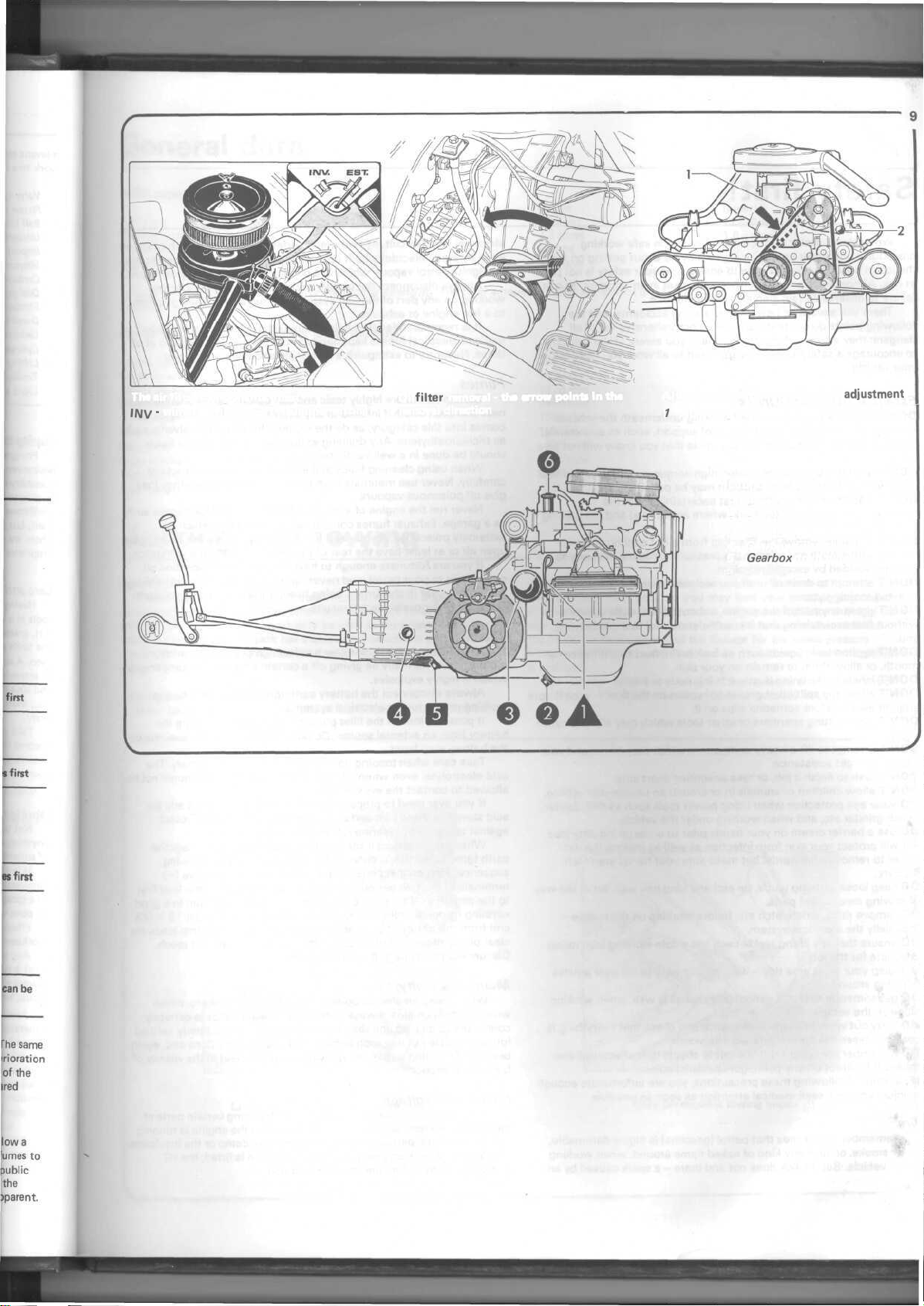
The air filter components. Inset
IIVV ' winter setting, EST - summer setting
Oil
filter
removal - the arrow points in the Alternator/water pump drive belt
removal direction
1
Adjusting bolt 2 Pivot bolt
Lubrication schedule
1 Dipstick
2 Sump drain plug
3 Oil filter
4 Gearbox filler plug
5
Gearbox
6 Oil filler
adjustment
drain plug
Page 11
Safety
first!
Professional motor mechanics are trained in safe working
procedures. However enthusiastic you may be about getting on with
the job in hand, do take the time to ensure that your safety is not put
at risk. A moment's lack of attention can result in an accident, as can
failure to observe certain elementary precautions.
There will always be new ways of having
following points do not pretend to be a comprehensive list of all
dangers; they are intended rather to make you aware of the risks and
to encourage a safety-conscious approach to all work you carry out on
your vehicle.
accidents,
and the
Essential DOs and DON'Ts
DON'T rely on a single jack when working underneath the vehicle.
Always use reliable additional means of
securely placed under a part of the vehicle that you know will not give
way.
DON'T attempt to loosen or tighten high-torque nuts (e.g. wheel hub
nuts) while the vehicle is on a jack; it may be pulled off.
DON'T start the engine without first ascertaining that the
transmission is in neutral (or
brake applied.
DON'T suddenly remove the filler cap from a hot cooling system cover it with a cloth and release the pressure gradually first, or you
may get scalded by escaping coolant.
DON'T attempt to drain oil until you are sure it has cooled sufficiently
to avoid scalding you.
DON'T grasp any part of the engine, exhaust or catalytic converter
without first ascertaining that it is sufficiently cool to avoid burning
you.
DON'T syphon toxic liquids such as fuel, brake fluid or antifreeze by
mouth, or allow them to remain on your skin.
DON'T inhale brake lining dust - it is injurious to health.
DON'T allow any spilt oil or grease to remain on the floor - wipe it up
straight away, before someone slips on it.
DON'T use ill-fitting spanners or other tools which may slip and cause
injury.
DON'T attempt to lift a heavy component which may be beyond your
capability - get assistance.
DON'T rush to finish a job, or take unverified short cuts.
DON'T allow children or animals in or around an unattended vehicle.
DO wear eye protection when using power tools such as drill, sander,
bench grinder etc, and when working under the vehicle.
DO use a barrier cream on your hands prior to undertaking dirty jobs
- it will protect your skin from infection as well as making the dirt
easier to remove afterwards; but make sure your hands aren't left
slippery.
DO keep loose clothing (cuffs, tie etc) and long hair well out of the way
of moving mechanical parts.
DO remove rings, wristwatch etc, before working on the vehicle -
especially the electrical system.
DO ensure that any lifting tackle used has a safe working load rating
adequate for the job.
DO keep your work area tidy - it is only too easy to fall over articles
left lying around.
DO get someone to check periodically that all is well, when working
alone on the vehicle.
DO carry out work in a logical sequence and check that everything is
correctly assembled and tightened afterwards.
DO remember that your vehicle's safety affects that of yourself and
others. If in doubt on any point, get specialist advice.
IF, in spite of following these precautions, you are unfortunate enough
to injure yourself, seek medical attention as soon as possible.
'Park'
support,
where applicable) and the parking
such as axle stands,
Fire
Remember at all times that petrol (gasoline) is highly flammable.
Never smoke, or have any kind of naked flame around, when working
on the vehicle. But the risk does not end there - a spark caused by an
electrical short-circuit, by two metal surfaces contacting each other, or
even by static electricity built up in your body under certain conditions,
can ignite petrol
Always disconnect the battery earth (ground) terminal before
working on any part of the fuel system, and never risk spilling fuel on
to a hot engine or exhaust.
It is recommended that a fire extinguisher of a type suitable for
fuel and electrical fires is kept handy in the garage or workplace at all
times. Never try to extinguish a fuel or electrical fire with water.
vapour,
which in a confined space is highly explosive.
Fumes
Certain fumes are highly toxic and can quickly cause unconscious-
ness and even death if inhaled to any extent. Petrol (gasoline) vapour
comes into this category, as do the vapours from certain solvents such
as
trichloroethylene.
should be done in a well ventilated area.
When using cleaning fluids and solvents, read the instructions
carefully. Never use materials from unmarked containers - they may
give off poisonous vapours.
Never run the engine of a motor vehicle in an enclosed space such
as a garage. Exhaust fumes contain carbon monoxide which is
extremely poisonous; if you need to run the engine, always do so in the
open air or at least have the rear of the vehicle outside the workplace.
If you are fortunate enough to have the use of an inspection pit,
never drain or pour petrol, and never run the engine, while the vehicle
is standing over it; the fumes, being heavier than air, will concentrate
in the pit with possibly lethal results.
Any draining or pouring of such volatile fluids
The battery
Never cause a spark, or allow a naked light, near the vehicle's
battery. It will normally be giving off a certain amount of hydrogen gas,
which is highly explosive.
Always disconnect the battery earth (ground) terminal before
working on the fuel or electrical systems.
If possible, loosen the filler plugs or cover when charging the
battery from an external source. Do not charge at an excessive rate or
the battery may burst.
Take care when topping up and when carrying the battery. The
acid electrolyte, even when diluted, is very corrosive and should not be
allowed to contact the eyes or skin.
If you ever need to prepare electrolyte yourself, always add the
acid slowly to the water, and never the other way round. Protect
against splashes by wearing rubber gloves and goggles.
When jump starting a car using a booster battery, for negative
earth (ground) vehicles, connect the jump leads in the following
sequence: First connect one jump lead between the positive (+)
terminals of the two batteries. Then connect the other jump lead first
to the negative (-) terminal of the booster battery, and then to a good
earthing (ground) point on the vehicle to be started, at least 1 8 in (45
cm) from the battery if possible. Ensure that hands and jump leads are
clear of any moving parts, and that the two vehicles do not touch.
Disconnect the leads in the reverse order.
Mains electricity
When using an electric power tool, inspection light etc, which
works from the mains, always ensure that the appliance is correctly
connected to its plug and that, where necessary, it is properly earthed
(grounded). Do not use such appliances in damp conditions and, again,
beware of creating a spark or applying excessive heat in the vicinity of
fuel or fuel vapour.
Ignition HT voltage
A severe electric shock can result from touching certain parts of
the ignition system, such as the HT leads, when the engine is running
or being cranked, particularly if components are damp or the insulation
is defective. Where an electronic ignition system is fitted, the HT
voltage is much higher and could prove fatal.
Page 12
General data
Refill capacities
Fuel tank
Cooling system (inc. heater)
Engine oil (sump and filter)
Gearbox/differential
Metric
50
litres
7.3 litres
4 litres
3.4 litres
Imperial
11
gallons
1.6 gallons
7 pints
5.9 pints
* Figure given is when full or quantity for regular changing. The total amount of oil in the circuit is 4.6 litres. The
2.8 litres.
Overall dimensions and weights (early models)
Length (overall)
Width
(overall)
Height (overall)
Wheel
base
Front track
Rear track
Body overhang from front axle centre
Body overhang
Turning circle
Kerb weight (full fuel tank)
from
rear axle centre
Metric
3890
mm
1590mm
1370
mm
2455 mm
1384mm
1351
mm
730mm
705 mm
9400
mm
830kg
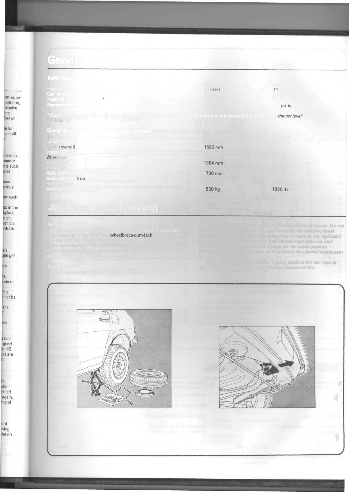
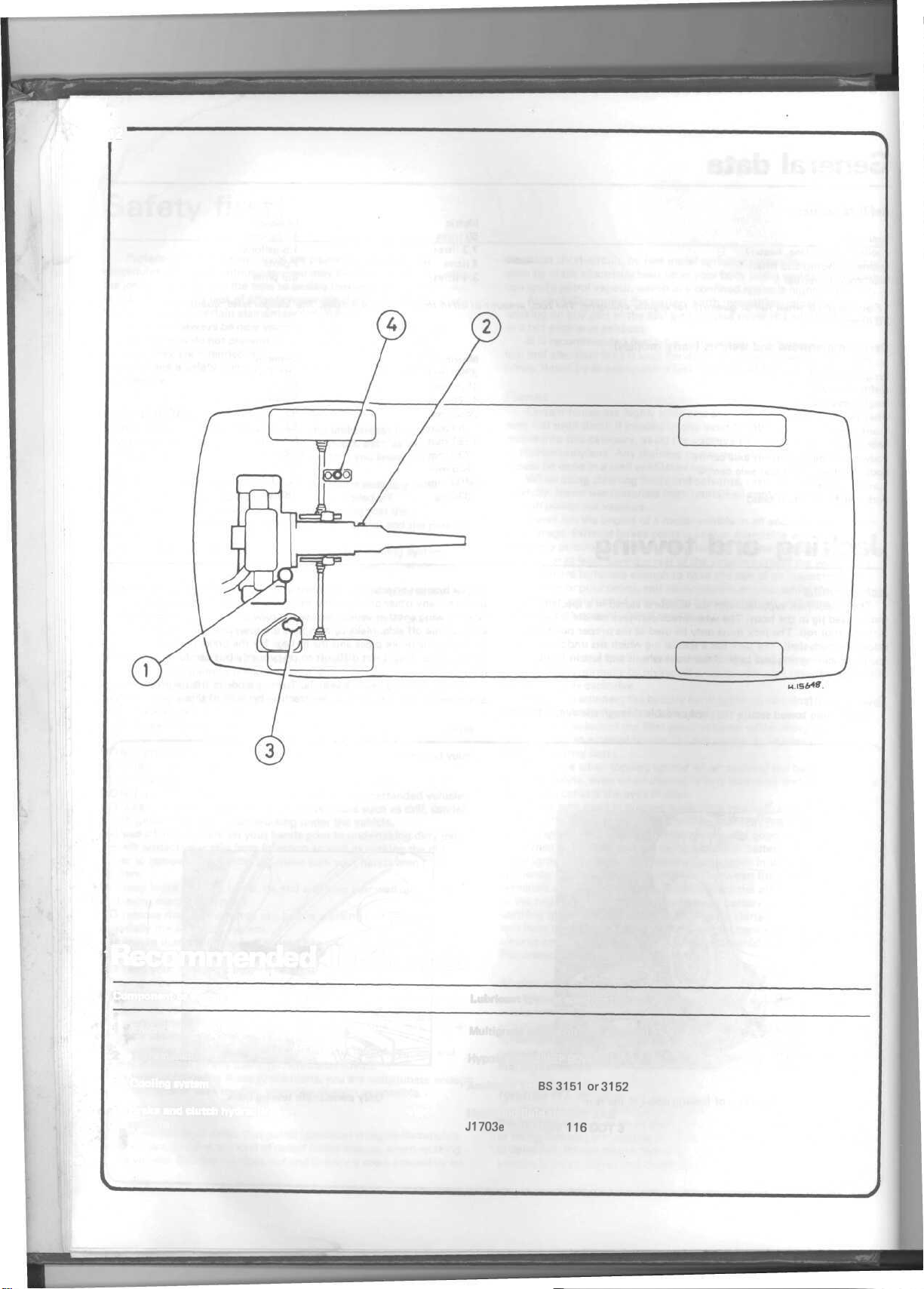
Jacking and towing
Jacking points
The scissor-jack supplied with the vehicle is stored in a specially
constructed jig in the boot. The
with the tool roll. The jack must only be used at the proper positions
below the bodyshell. The jack has a special lug which sits under an
opening/locating ring just behind the front wheels and just in front
of the rear wheels
wheelbrace-cum-jack
handle is kept
Towing points
When being towed secure the rope or cable through the eye of the
special bracket attached to the front underside centre of the car. Do not
tow from any other point or you may find your car changing shape!
When towing another vehicle secure the rope or cable to the rigid back
axle, on the off side. Make certain that the tow rope does not foul
the hydraulic brake pipes and the linkage for the brake pressure
limiter valve. This is not difficult to do properly but careful attachment
is necessary.
Do not tow too
any vehicle - the Alfasud can lose traction because of this.
heavy a vehicle.
'danger
Imperial
151.7
62 in.
53.4
in.
95.7
in.
53.9
in.
52.6
in.
28.4
in
27.4
in.
366.6 in.
1830
Ib
Towing
in.
tends
level'
quantity is
to
lift
the
front
of
Location of jacking point at the rear
Only permissible towing hook
Page 13
12
Recommended lubricants
Component or system
1 Engine
2 Transmission
3 Cooling system
4 Brake and clutch hydraulic
systems
Lubricant type or specification
ft/lultigrade engine oil SAE 10W/50
Hypoid gear oil EP 80W/90
Antifreeze to
Hydraulic fluid to DOT SAE
J1703e
BS3151
or FMV55
116
or
3152
DOT 3
Page 14

Chapter 1 Engine
For
modifications,
Contents
and information applicable to later models, see Supplement at end of Manual
Descriptions
Engine removal 5
Engine removal from gearbox ... ... ... ... ... ... 6
General description ... ... ... ... ... ... ... 1
Major operations which entail engine removal 3
Major operations which may be carried out with the engine in the car 2
Method of engine removal ... ... ... ... ... ... 4
Dismantling
Alternator - removal ... ... ... ... ... ... ... 10
Big-end bearings and piston - removal 21
Camshaft drive belts - removal ... ... ... ... ... ... 14
Carburettor - removal ... ... ... ... ... ... ...
Crankcase front cover - removal 20
Crankcase rear cover -
Crankshaft
Cylinder heads and
Distributor-removal
Engine dismantling - general ... ... ... ... ... ... 7
Flywheel - removal 22
Fuel pump - removal ... ... ... ... ... ... ... 13
Inlet manifold and thermostat housing - removal ... ... ... 12
Main bearings and crankshaft - removal ... ... ... ... 24
Oil
Oil pump - removal ... ... ... ... ... ... ... 19
Sump - removal ... ... ... ... ... ... ... ... 18
Water pump and pulley - removal 16
pulley
filter-removal
removal...
and
drives-removal
camshafts-removal
8
9
... ... ... ... ... 23
17
... ... ... ... 15
11
Inspection and renovation
Camshafts, tappets, camshaft pulleys and belts
Crankcase/cylinder
Crankshaft, big-end and main bearings
block
32
26
28
Cylinder compression test
Cylinder heads and valves, plus decarbonisation
Flywheel (and starter ring gear)
Liners, pistons, piston rings and connecting rods
Oil pump ...
Reassembly
Alternator and drivebelt - replacement and tension ...
Camshaft belts and valve timing
Carburettor - replacement
Crankcase preparation ...
Crankshaft and main bearings - reassembly ...
Cylinder heads and camshafts - reassembly and replacement
Distributor - replacement
Engine -
reassembly
Flywheel Front crankcase cover - replacement ...
Fuel pump - replacement
Inlet
Oil pump Pistons and connecting rods - reassembly and replacement
Rear crankcase
Sump - replacement
Tappet clearance adjustment ...
Water pump and pulley - replacement
Ancillary sender units, oil filter and other parts
replacement...
manifold - replacement ...
replacement...
general
cover-replacement
Engine replacement in the car
Engine attachment to gearbox ...
Engine replacement into car
Fault diagnosis - engine
Starting engine and running in ...
25
31
29
27
30
48
42
51
34
35
41
46
33
38
39
47
50
44
36
37
45
43
40
49
52
53
55
54
Specifications
Engine - general
Type
Code number
Bore
Stroke
Capacity ...
Compression ratio
Octane rating
Horsepower:
SAE
DIN
Torque:
SAE
DIN
Idling speed
Firing order
Oil capacity (both)
Horizontally opposed, flat
camshaft on each cylinder bank
Alfasud
301.00
8.8:
1
4-cylinder,
80mm (3.15 in)
59mm (2.32 in)
1186cc(72.4cu in)
99
73 at 6000
63 at 6000 rpm
9.8 kgm at 3500 rpm
8.5 kgm at 3500 rpm
rpm
800 to
1000
1-3-2-4
4 litres (7 Imp. pints)
(sump and filter)
water cooled, single overhead
Alfasud
Tl
301.04
9.0:1
68 at 6000 rpm
rpm
Page 15

14
Chapter
1/Engine
Essential differences between the Alfasud and Alfasud
1 Camshafts and valve timing
2 Cylinder heads
3 Valves
4 Carburettor
Lubrication system
Type ... ... ... ... ... ... ... ... ... ... Wet
Filter Full flow - replaceable cartridge
Capacity:
With filter change ... ... ... ... ... ... ... ... 4 litres (7 Imp. pints)
Without filter change 3.6 litres (6.3 Imp. pints)
Oil
required
Oil pump ... ... ... ... ... ... ... ... ... ... Twin gear
Oil pump gear/body end-clearance Nil
Oil
pump
Oil pressure relief valve
Crankshaft and main bearings
No. of bearings, and type
Journal diameters 59.944 - 59.975 mm
Undersize main bearing shells 0.25, 0.50, 0.75, 1 mm
Bearing clearance
Crankshaft endfloat
Journals, maximum ovality ... ... ... ... ... ... ... 0.02 mm
Crankcase
Main bearing bore diameter 63.663 - 63.673 mm
Thickness of seating for thrust washers (side-to-side) 23.68 - 23.73 mm
Maximum allowable misalignment of bearing ... ... ... ... 0.02 mm
Camshafts and
Camshafts drive ... ... ... ... ... ... ... ... ... 2 gear driven toothed belts, external
Bearings ... ... ... ... ... ... ... ... ... ... Direct in carrier
Journal diameters:
Bearing housing diameter:
Endfloat
Width of camshaft register housing 5.45 - 5.5 mm
Thickness of rear cover gasket
Width of camshaft register ... ... ... ... ... ... ... 5.5 - 5.55 mm
Diameter of tappet bucket housing 36 - 36.025 mm
Diameter of tappet 35.973 - 35.989 mm
Maximum total misalignment of camshaft bearings ... ... ... ... 0.02 mm
Truth of machined faces 0.03 mm
Connecting rods and bearings
Type
Big-end bearings ... ... ... ... ... ... ... ... ... Thin wall shell
Small-end bush ... ... ... ... ... ... ... ... ... Steel bush, lead bronze coated
Big-end journal diameter 49.987 - 50 mm
Big-end diameter 53.696 - 53.708 mm
Undersize big-end bearing shells 0.25, 0.50, 0.75, 1 mm
Clearance of big-end bearing to journal 0.026 - 0.063 mm
Gudgeon (wrist) pin/bush interference ... 0.024 - 0.039 mm
Crankpin, maximum ovality ... ... ... ... ... ... ... 0.02 mm
Cylinders
Type ... ... ... ... ... ... ... ... ... ... Machine into cylinder block with liners
Oversize (liner diameter) ... ... ... ... ... ... ...
Maximum divergence from measurement ... ... ... ... ...
Cylinder heads
Type Aluminium alloy, one per pair of cylinders, cross flow. Alfasud and
Pistons and rings
Type ... Light alloy. Alfasud and Alfasud
Cylinder clearance limit 0.03 - 0.05 mm
Height of piston ring grooves:
to
fill
from lower
gear/backlash...
0.028 - 0.063 mm
limits
bearings
Front 34.94 - 34.956 mm
Centre 46.445 - 46.456 mm
Rear 46.94 - 46.956 mm
Front
35.015-35.040
Centre 46.515 - 46.54 mm
Rear 47.015 - 47.040 mm
0.1-0.3
Forged steel
Top compression 1.525 -
Lower compression 1.775 - 1.795 mm
Oil control ...
4.015
to
upper marks
... ... ... ... " ... ... ... Nil
set
at 4.5 kg/sq cm
-3,
0.05 - 0.24 mm
0.21-0.33
on the
Tl
engines:
dipstick
... ... 1.2
0.2,0.4,0.6mm
0.010mm
Alfasud Tl use different heads
sump,
pressure and splash
thin wall shell
mm
mm
1.545
mm
- 4.035 mm
mm
litres
(2.1 Imp. pints)
Tl
use the same pistons
Page 16

Chapter
Piston ring thickness:
Top compression ... ... ... ... ... ... ... ...
(
Lower compression ... ... ... ... ... ... ... 1.728 -
Oil control 3.978 - 3.990 mm
Piston oversizes
Gudgeon wrist pin ... ... ... ... ... ... ... ... Steel tube
Clearance of gudgeon pin to piston 0.007 0.016mm
Top compression ring gap ... ... ... ... ... ... ... 0.30 - 0.45 mm
Lower compression ring gap ... ... ... ... ... ... ...
Oil control ring gap ... ... ... ... ... ... ... ... 0.25 - 0.40 mm
Gudgeon pin diameter 20.006 Tappet cam followers
Type
..
Diameter of tappet bucket 35.973 - 35.989 mm
Valves,
Inlet:
Valve head diameter 38 - 38.2 mm
Stem diameter
Seat width
Seat angle 90° - 90°
Guide bore diameter 8.013 - 8.031 mm
Exhaust:
Valve head diameter 33 - 33.2 mm
Stem diameter
Seat width
Seat angle 90° - 90°
Guide bore diameter 8.030 - 8.048 mm
Maximum rock in guide (both) ... ... ... ... ... ... 0.9 mm
Valve springs:
Height of
External spring: spring length and load with valve closed ... ... 33.75 mm/22.95 - 24.35 Kg
Internal spring: spring length and load with valve closed
Valve (tappet) clearance (oil removed from camshaft chest) (cold)
Inlet
Exhaust
Valve timing Alfasud Alfasud
Inlet
Inlet
Exhaust opens bbdc 54° 45°
Exhaust closes atdc 6° 7°
0.2,0.4,0.6mm
... ... ... ... ... ... ... ... ... Bucket type, encasing valve
valve seats
0.35-0.40
opens
closes
and
timing
7.895-8
1.07-1.37
7.985-8
1.26-1.56
free
spring ... ... ... ... ... ... ... 46 mm
31.75
0.45-0.50
btdc 6° 12°
abdc 54° 48°
1/Engine
1.478 - 1.490
1.740
0.30 - 0.45 mm
mm/11.35
mm
mm
21.00
mm
mm
mm
30'(included
mm
mm
30'(included
mm
mm (0.018/0.020 in)
angle of seat faces)
angle of seat faces)
- 12.15 Kg
(0.014/0.016
spring,
bearing directly onto camshafts
in)
Tl
15
and
Torque wrench settings
Main
bearing cap
Side brace bolts*
Connecting rod bolts
Flywheel bolts* 9.6-10.7
Crankshaft nut
Drive pulley to camshaft* 6.4-7.1 46.2-51.3
Cylinder head bolts*
Camshaft housing/cylinder head bolts 1.9-2.4
Oil pump set screws:
Large 1.9-2.4
Small
Fuel
pump
Inlet manifold 1.9-2.4
Timing belt tensioner nut:
Cold engine
Hot engine 3.0-3.6
*OHed
threads
1 General description
The Alfasud engine is not particularly conventional. As a flat four,
single overhead
present time. The specifications explain the basic workings of the
engine adequately, this paragraph will explain its significance to the
home mechanic. Do not be put off the Alfasud engine by its
description, nor by what it looks like sitting in the car. It is a relatively
simple unit to remove and equally so to dismantle. No special tools
are strictly necessary but it is a must to use a wide selection of good
bolts*
6.7-7.4
4.1-5.0
4.4-4.9
12.0-14.7
8.3-8.9
0.8-1.0
nuts 1.9-2.4
3.8-4.7
camshaft,
water cooled engine it is unique at the
'paper'
kg f m Ib
48.5-53.5
29.5-36.0
31.8-35.4
69.4-77.3
86.7-106.4
60.0-64.3
13.7-17.3
13.7-17.3
5.7-7.2
13.7-17.3
13.7-17.3
27.4-33.8
21.6-25.9
quality tools. Many spanner (metric) sizes are used; it would be unwise
to tackle the job without a full metric socket set, open and ring spanner
set, screw drivers,
able as the majority of the engine components are assembled at the
factory with gasket cement and thread locking fluid. Have engine and
grease cleaner available, too, as a clean engine is much easier to work on
in this case, than a dirty one. Lots of lint free rag and wooden blocks
to support the components will help. Follow the instructions very
carefully, one sequence out could cost extra time and money. At
times
it is
when this is so.
necessary
hammers,
to
have
punches etc. Have some easing fluid avail-
someone
f ft
else
help you;
you
will
be
told
Page 17

16
7 Cylinder block
2 Main bearing cross-bolts
3 Main
bearing
cap
4 Front engine
5
Front
6 Oil seal
7 Gasket
8 Pressure sensor
cover
bolts
mounting
13
Fig. 1.1. Basic, static engine components
9 Rocker cover
10
End cover
11
Gasket
12 Cam
13 Oil seal
14 Gasket
15 Head gasket
housing
Page 18

17-
16 Sump gasket
17 Sump
17
16
18
Crankcase rear cover
19 Oil seal
20 Oil
filler
21 Dipstick
22 Dipstick stop
23 V ring
24 Oil filter
Page 19

18
Chapter
1/Engine
2 Major operations which may be carried out with the engine in the
car
Little major work can be carried out upon the engine with it still
in the car. As it is relatively easy to take the engine and gearbox out
of the car you may
be easily carried out with the engine in the car. Here is a list of those
tasks which can be carried out with some indication as to whether or
not it would be better to remove the engine:
Replacement of timing toothed belts (easy)
Replacement of inlet
alternator and alternator drive belt, radiator and spark plugs (easy)
Water pump (possible but very difficult due to interference fit of
pump)
Sump (easy)
Big-end bearings (difficult and from below)
Oil pump (easy)
Cylinder heads (see Chapter 12)
find
that nothing more than routine servicing can
manifold,
carburettor,
distributor,
exhaust,
3 Major operations which entail engine removal
It is necessary to remove the engine and gearbox from
carry out the replacement of the following components:
1 Clutch and gearbox
Crankshaft, flywheel, main bearings, pistons and connecting rods
4 Method of engine removal
The engine and gearbox must be removed together complete and
must always be done from below. This may mean either lowering the
engine/gearbox from a hoist under the
bodyshell to sufficient height, or to wheel the engine and gearbox from
under
the car on a
Whatever happens ideal conditions are necessary: flat floor, elbow
hoist and tall stacks.
trolley
jack
and
bodyshell,
physically
having jacked up the
lift
the
ths
bodyshell
car to
over
room,
it.
5.8a The radiator top support
5.10
Disconnect the starter motor cables
5.8b Removing the radiator
5.15
Removing the air cleaner cover
5.9 Accelerator return spring
5.17
Disconnecting the choke cable
5.22 Front brake pipe union
5.23 Moving the clutch slave cylinder out of the
way
Page 20

plete and
hell over it.
elbow room,
5.28 The reversing light switch
5.29 Exhaust pipe connection
5.30 Camshaft cover and bracket
5.31 Rubber
*
I
5.34 Remove the Allen screws
shafts crossmember
O-rings
support exhaust system 5.32 Exhaust
from
the drive- 5.36 Front engine mounting is secured to
pipe-to-cylinder
head connections 5.33 Disc dust cover seen from below
5.37a
Crossmember-to-bodyshell
bolts
attachment
5.37b Anti-roll bar mountings need not be 5.37c Crossmember and anti-roll bar can be
disturbed removed complete
5.38 Gearbox tail mounting
Page 21

20
Chapter
1/Engine
5.39 Engine centre mounting
5.40 Handbrake cable is visible to the rear of
the engine mounting
5.41
b Raise the bodyshell to clear the engine
5 Engine removal
1 Place the car in a convenient spot where it is possible to gain access
underneath it for its full length and where it is possible to leave it
jacked up and supported on stands. A hoist can be used or instead a
trolley
jack
to
lift
the
bodyshell
or
lower
the
engine,
and
room
to use
them.
2 Run the engine until it is at its normal working temperature.
Switch off and chock the rear wheels on both sides of the car. Open
the bonnet and disconnect the battery earth lead. Drain the engine
oil.
3 Remove the front grille. It is fixed by one screw on each side and
four on the bottom edge. Pull off the central badge (it is a push-on fit)
and remove the last screw which is mounted behind it.
4 The four bonnet hinge bolts are now exposed. Have someone hold
the bonnet and remove the four bolts. Squeeze the bonnet support,
unclip it and remove the bonnet to a safe place.
5 It is not
necessary
but it
will
give greater
working
space
if you now
drain the cooling system and then remove the radiator. Jack up the
front of the car and support it. Obtain two receptacles which will
hold about a gallon each and place them under the coolant drain
plugs, one under the centre of each cylinder block. Undo the plugs
and allow the radiator and the cylinder blocks to drain, once you
have removed the expansion chamber filler cap. Remove the
receptacles and lower the car.
6 Remove the bottom and top hoses to the radiator by pinching
the two hose clips on each hose, one at each end, and carefully
levering
off the tight hoses. Remove the expansion chamber hose
at the radiator by unscrewing the hose clip and slipping it off.
7 Pull off the electrical connections to the thermostatically
controlled fan switch and one of these to the fan. The other wire
to the fan is an earth wire and should be disconnected at earth
which is one of the headlamp support studs.
8 Undo the one radiator support which is in the centre of its top
chamber. This is a one stud with a nut fixing, on rubber. Undo the
nut and carefully pull the radiator back at the top towards the
bulkhead, and lift out.
5.41
a Lower the engine to the ground
9 Disconnect the accelerator control linkage from the lever on the
carburettor. You will need to unhook the return spring and a special
connecting ring, a sort of circlip.
10 Disconnect the engine and transmission earth cable which is
connected to an end cover nut adjacent to the starter motor. Discon-
nect the two starter motor cables. Pull off the water temperature
warning light wire from the sender unit on the right hand bank of
cylinders. All these wires are in the same harness. Tie them all back
out of the
11
way.
Pull off the terminals from the alternator and then release the
cables from the retaining clip on the engine lifting hook which is on
the outer end of the inlet manifold fixing. Tie back.
12 Pull off the high tension and low tension cables from the
distributor and tie back.
13 Pull off the cable from the sender unit for the engine oil pressure
warning light.
14 Pull off the
carburettor
air cleaner warm air intake pipe from its
lower fixing and unclip the hose clip at its top end on the air cleaner.
Remove.
15 Unscrew the wing nut on the top of the air cleaner, remove cover
and the element inside. Now remove the air cleaner body and gasket
from the carburettor. This is fixed by two nuts and studs on the
Alfasud and four on the Alfasud
Tl.
Pull off the breather pipes which
come with it.
16 Release the support bracket for the accelerator cable from the
top of the carburettor which is now exposed. It fits over the top of
the inlet.
17 Disconnect the flexible cable and the outer cable of the choke at
the clamp and screw. Two small spanners will be necessary here.
18 For ease of movement remove the plug caps and leads together
with the distributor cap. Then remove the rotor arm.
19 Pull off the brake servo pipe to the inlet manifold and tie back, on
those models so
fitted.
20 Unclip the hose clips and remove as many of the heater hoses as
possible. Remove them from the front side of the inner bulkhead only;
do not remove them at the heater itself. A screwdriver, carefully used
to lever off the hoses, always helps. Some of them are clipped to the
engine oil filler pipe, disconnect here too. Do not forget the pipe to the
expansion chamber also.
21 Disconnect the petrol feed pipe to the fuel pump and tie back.
22 Remove the cap to the brake fluid master cylinder reservoir and
place a piece of thin polythene over the opening and replace the cap.
This prevents brake fluid leakage for the next operation. Disconnect
the front brake flexible pipes from the rigid pipes which come direct
from the master cylinder at the special unions, one on each side of
the inner bulkhead, on the front side. Two spanners will be necessary.
Seal off the pipes with suitable plugs.
23 To remove the clutch slave cylinder from the engine block locate
it close to the engine oil filler pipe. On the far side there is a large
circlip which holds the body of the slave cylinder in place. Release
this circlip and the slave cylinder will come back through its fixing
and can be placed out of harm's way on the other side of the inner
bulkhead. There is no need to disconnect the piping.
Page 22

Chapter 1/Engine
21
24
Inside
the car
pull
off the
at the foot of the gearlever and the rubber gaiter below that. They
are nothing more than simply clipped in.
25
Inside
the car
handbrake.
the pivot pin so that the lever is loose. Now remove the
handbrake
the cable inner about to enable the ferrule to release itself from the
cable
and be
pushed through the lever at an angle.
26 Everything that needs to be done from above the engine has been
completed.
the
place
the front of the car. Remove the
27 Drain the gearbox oil. Replace the plug when the oil has drained.
28
From
switch
cable
drive
cable
retaining spring.
29 Go to the left-hand rear road wheel and just in front of it spray
the
exhaust
a
releasing
breaking
30 Now go to the
engine.
There
exhaust
and to the end of the
air
cleaner
intake.
31 Go
back
clamp
completely.
and
try to
have
to
split
back
the
sets
of
rubber
and rear silencer.
32 Undo and remove the eight nuts which support the four pipes of
the exhaust manifolds at the cylinder heads. Then remove the two
rubber
'0'
part
of the
Obviously
the front or the back as it is released.
33 Now remove the two front disc dust covers. These are individually
fixed
with four
bracket
on the
on the top top side of the cover located into the side of the gearbox.
34 With the appropriate alien key undo and release the alien screws
which
bolts
Allen
screws
be
necessary
releasing
expensive
shafts
and tie
the inner bulkhead.
35
From
hoist.
There
Use
these
the gearbox. For the moment support the engine on the two eyes.
Another
method
with
the
not so
good
36 The front crossmember should come out with the anti-roll bar
attached.
arm/crossmember
to the inner side of the
remove
the two
to
the crossmember. These are located just in front of the anti-roll
bar, in the centre.
37 At each end of the front crossmember are two bolts which locate
it to the
engine
support (front)
anti-roll bar still fixed, should come away. The engine and gearbox
should be supported, of course, by the sling or trolley jack together
with the rear centre mounting and the rear gearbox mounting.
38 Remove the two support bolts for the rear gearbox mounting
located
at the end of the
39 From above with the tail shaft of the gearbox supported by another
pull
Undo
the nut on the
cable
ferrule
pushed
through.
Now
jack
that
you can let it
below
the
gearbox
by
pulling
from
the
side
connection (the exhaust
agent.
The
will
be
helped
front
is a tin
warm
air
intake.
to the
exhaust system,
Tap the
make
the
joint
them.
tail pipe
agent.
to
above
lifting
Undo
bodyshell.
Use a
off the
'O'
ring
ring exhaust system
total system.
it
will
help
bolts.
underside
the two
front
will
be
tight
to use a
Watch
replace. Never
them back, preferably upwards
support
are two
plus a third
lifting
is to
head
protected
but it
will
the
bolt
to the transverse suspension arm at the strut, close
bolts
With these four removed the
gearlever
off the
handbrake lever gaiter
which
locates
It
up the car as
rest
at the
it
off.
Then
of the
joint
is
bound
if you use
of the car to the right-hand exhaust below the
moulding
camshaft cover.
Remove
connection
move
large screwdriver
front
exhaust
supports
The
system should
to
have another person
Two
appear
of the
drive
as
they
piece
of
tubing
the
rubber bellows
'bodge'
the
engine
eyes,
point
when
support
the
work
if no
which
front
hub. Do this on each side. Slacken and
from
below
and
both
tail
shaft.
knob.
Then
handbrake lever
the
has a
step
high
as you can at the
whilst
the
front
wheels.
rear,
disconnect
disconnect
gearbox
by
splits
to be
releasing
which
is
the two
split
with a copper-headed hammer
in
some
part
of the
and
supports
from
below
gearbox sump
shafts
to the
are
'Loctited'
on the
the
proper
and
gearbox
one on
each
it
becomes
engine
with a piece
hoist
is
locates
the
that
fix the
trailing
suspension
pivot
cable
to the
on it and
engine
is
the
speedometer
unclipping
here
into
rusted together
fluid
now.
bolted
to a
This
bolts
and
and
release
way. Eventually
or
punch
system.
Undo
remove
at the
other
now
drop
under
and
bolt
and the
disc/hub
into
Allen
key
as you do
tool.
with
string
with a sling
end of the
visible
from
below
of
wood.
available.
rear
end of the
front
front
pull
out the
and
release
pin,
remove
circlip
lever. Juggle
this
has to be
front
out.
Support
the
reverse
the
special
two
parts)
and its
bracket
is the
on the
carburettor
release
the
exhaust
you
will
to try to tap
the two
the
tail
pipe
end of the
away.
the car to
into a special
other
two are
flanges. These
position.
plus some
this
for
they
Release
the
or
wire
and a
inlet
through
engine
links
the top of
with a trolley
This
method
suspension
mounting
crossmember,
with
'bag'
the
on the
in
light
with
the
front
hold
It may
are
half
to
manifold.
jack
is
the
person under the car (no strength is needed, just a steadying hand)
slacken and remove the centre engine mounting bolt located under
the centre of the inner bulkhead. The engine and gearbox are now
loose.
40 If you are using a hoist allow the engine/gearbox to be lowered
to the ground. Now disconnect the handbrake cable from both the
front brake calipers. A pair of grips and a stout screwdriver are
necessary to do this with some force. The return spring on the cable
is very stiff. Once done, tie the handbrake cable back. Now relocate
the hoist so that it is mounted at three points, the third being through
the support on the gearbox from whence the handbrake cable came.
Raise
the
engine
and
gearbox
unit
just
off the
ground
and
pull
forward
and out
from
under
the
car.
At
some
point
necessary
have
to
is a
minimum
total
unit.
from
you
to
pull
the studs around
have to remove the hoist to clear the front of the car. Take the
engine and gearbox to the point where you intend to work. Three
strong
men
could
lift
the
total
unit
41 If you are using a trolley jack, lower the engine and gearbox unit
and remove the handbrake cable as described in the previous paragraph.
At the jack's lowest point pull the whole unit forward until you are
ready
to
clear
the
over
the
engine
and two
will
persons.
6 Engine removal from gearbox
1 Place the engine and gearbox (preferably) on a strong working
surface
still
the pair on the ground.
2 Remove the nuts, bolts and washers which support the starter
motor to the bell housing. Remove the starter motor.
3 Remove from the underside of both units the flywheel protection
cover. This is retained by a number of bolts and washers to the rear
engine cover and by one at the bottom to the gearbox casing.
4 Remove all the remaining nuts and washers
the
bell
housing.
the gearbox from the engine. Take care with the gearbox shaft which
locates through the centre of the clutch. Do not allow any pressure on
it - pull off straight.
have
with
underside
and
gearbox.
to
the
Both
lift
sling
engine
the
just
complete.
of the
car.
One
person
bodyshell.
supporting
and
gearbox
It
is
will
This
the
may now be
will
lift
the
number
If not
split
it
again
the car
engine
place
by
lifting
of
Dismantling
7 Engine dismantling - general
1
Owners
strong work bench and many tools and pieces of equipment, which
make their life much easier when going through the process of dis-
mantling
the
which,
to the job in the long run. It is essential to have sufficient space in
which to work. Dismantling and reassembly is not going to be completed all in one go and it is therefore absolutely essential that you
have sufficient area to leave things as they are when necessary. A
strong work bench is also necessary together with a good engineer's
vice. If you have no alternative other than to work at ground level,
make
wooden or wood composition material on which to work. If dirt and
grit are allowed to get into any of the component parts all work which
you carry out may be completely wasted. Before actually placing the
engine wherever it is that you may be carrying out the dismantling,
make sure that the exterior is now completely and thoroughly
cleaned.
2 Once dismantling begins it is advisable to clean the parts as they
are removed. A small bath of paraffin is about the best thing to use
for this, but do not let parts which have
immersed in paraffin otherwise there may be a residue which could
cause harmful effects later on. If paraffin does get into oilways every
effort should be made to blow it out. For this it may be
carry
hose. Short oilways such as there are in the crankshaft can be cleared
who
have
dismantled
an engine. For those who are doing a dismantling job for
first
time,
there are a few
if not
sure
the
particular
acquired,
that
the
will
floor
part
only
is at
to a
engines
'musts'
cause
least level
garage
fitted
will
know
the
in the way of preparation
frustration
and
oilways
and
covered
with a suitable
in them become
with a high pressure
need
long
delays
necessary
for a
to
air
Page 23

22
Chapter 1 /Engine
easily with pipe cleaners.
3 Always obtain a complete set of gaskets when the engine is being
dismantled - no gaskets on an engine are re-usable and any attempt
to do so is quite unjustified in view of the relatively small cost involved.
Before throwing any gaskets away, however, make sure that you have
the replacement to hand.
obtained it may be necessary to make one, and the pattern of the old
one is useful in such cases.
4 Generally speaking, it is best to start dismantling the engine from
the top downwards.
times so that it does not topple over whilst you are undoing the very
tight nuts and bolts which will be encountered. Always replace nuts
and bolts into their locations once the particular part has been removed,
if possible. Otherwise keep them in convenient tins or pots in their
groups, so that when the time comes to reassemble there is the
minimum of confusion.
8 Distributor - removal
1 The distributor cap, plug leads and caps should have been removed
already. So should the rotor arm. Pull off the vacuum advance pipe at
the carburettor and leave it attached to the distributor.
2 There is no need to record the position in which the
fixed to enable quick and accurate ignition timing upon replacement
as static timing marks are provided on a dowelled flywheel and there
is a cut on the rim of the distributor body where the caps fit to align
the rotor arm. Also there are adequate instructions for ignition timing
in Chapter 4. The distributor is therefore quickly removed.
3 Slacken the nut fixing the distributor to the adjusting plate on the
rear crankcase cover. Remove the nut and pull the distributor away.
If,
for example, a particular gasket cannot be
In
any case, make sure it is firmly supported at all
distributor
is
9 Oil filter - removal
1 Withdraw the dipstick.
2
Hold
a rag
under
the oil
seal
to
catch
the oil
which
will
flow
filter
off the
gasket.
out
body
fuel
when you release the oil filter. Now use a strap or chain wrench around
the oil filter body and release, unscrew and discard it. An alternate
method if a proper wrench is not available is to unscrew the
using a hammer and screwdriver to drive it in an anticlockwise direction.
3 Always use a new filter on a rebuilt engine.
10 Alternator - removal
1 First slacken the bolts which adjust the alternator drive belt using
the alternator body as a fulcrum. Loosen and remove the alternator
drive belt. You must of course slacken two bolts to do this, one is on
the adjuster plate and the other is the alternator pivot bolt.
2 Slacken and remove the two bolts which attach the adjuster plate
to the front crankcase cover. Now remove the alternator pivot bolt
and remove the alternator still attached to the alternator adjuster plate.
11
Carburettor - removal
1 The carburettor is easily removed from the inlet manifold. The
Alfasud carburettor is attached by two studs and nuts whilst the
Alfasud
Tl
the
line. Do the same at the fuel pump and remove the pipe.
2 Now carefully slacken the carburettor fixing nuts, remove and
then
is attached by four studs and nuts. First, however, slacken
hose
clip
to the
lift
fuel line
off the
carburettor, followed
on the
carburettor
by the
spacer
and
pull
and
9—
12
Fig. 1.2. Crankshaft, pistons and flywheel
Crankshaft
Connecting rod
3 Gudgeon pin
4 Piston
Piston rings
Big-end
bolt
Drive pulley
Toothed belt drive wheels
Woodruff key
10 Plug
11 Peg
12 Thrust washers
13 Peg
14 Bush
15
Skew gear
16
Special flywheel washer
17
Flywheel
18 Flywheel bolt
Page 24

Chapter
T/Engine
23
12 Inlet manifold and thermostat housing - removal
1 The inlet manifold is held at each end, on each bank of
by three studs and nuts. See paragraph 3 before attempting to remove.
To remove, unscrew gradually the six nuts, three at each end, remove,
and
then carefully
engine
lifting
of the nuts it may be necessary to first pull off the HT lead clips held
by the lifting hooks.
2 The thermostat housing is a little more complicated as it should
include the water inlet adapter.
3 The thermostat housing is attached to the inlet manifold by two
studs and nuts. It is easiest to remove the thermostat housing once the
inlet manifold has been removed from the engine. This is quite possible
if you first slacken and then pull off the coolant hose which connects
the thermostat housing to the water inlet adapter.
4 To remove the thermostat housing from the inlet manifold remove
the two nuts from the fixing studs and pull off.
5 To remove the water inlet adapter from the crankcase, slacken and
remove
the
hose
should
13 Fuel pump - removal
1 The fuel pump is fixed to the crankcase adjacent to the flywheel
close
to the
2
Slacken
pump, gasket, spacer and operating rod which come away loose.
14 Camshaft drive belts - removal
1 Turn the engine to bring No 1 piston to TDC on the compression
stroke (see Section 42). The engine may be turned using a 30 mm
spanner
on the
engaging top gear and pushing the car along.
2 If not already done, remove the alternator drivebelt and the cam-
shaft
drivebelt covers
3 Slacken the nut which secures the right-hand camshaft drivebelt
tensioner. Relieve the tension from the belt and tighten the nut to
secure
the
4 Remove the right-hand drivebelt from the drive wheels.
5 Repeat the procedure on the left-hand side of the engine and
remove
6 Do not rotate the crankshaft or
belt(s) removed. There is a risk of piston/valve contact and subsequent
tensioner
the
lift
fixing
be
located
oil
filler
remove
camshaft
(if
in
drivebelt.
the
nuts
the two
pulley
fitted).
this
hooks come away
four
still
engine
and
left-hand
whole
with
from
to the
tube.
It is
nuts
bolt,
position.
manifold
the
the
studs
water
inlet
fixed
on the
or
(with
either
off.
Of
manifold
and
lift
adapter.
by two
fixing
the
engine
camshaft with the
cylinders,
course,
the two
nuts.
To
undo
off.
The
connecting
studs
and
studs, remove
nuts.
in the
drive-
the
car)
some
by
damage, if this is done. Small movements of the camshafts, such as may
be necessary when refitting the drivebelt(s), should be made carefully
and without force.
7 Refer to Section 42 for the refitting procedure. Note that at some
stage it will be necessary to remove the camshaft covers (if not already
done) in order to inspect the camshaft timing marks.
15 Cylinder heads and camshafts - removal
For cylinder head
Chapter
12.
1 The camshaft housing with the camshaft installed can be removed
from the cylinder head with the head still attached to the crankcase.
For a complete stripdown it is easier to remove the cylinder head with
the camshaft housing still attached and then remove the camshaft
housing from the head afterwards.
2 Using a Phillips screwdriver slacken and remove the camshaft
housing cover and gasket. Held inside the housing is a quantity of oil if you have a suitable syringe suck up this oil to avoid an undue mess;
if not leave the oil there and pour it away after the head is removed.
3 Slacken the six large cylinder head bolts - three are outside the
housing and three are inside. Slacken these diagonally, remove and
then pull off the cylinder head and camshaft housing intact (watch
the oil if still in the housing). If the head will not shift tap it gently
with a copper-headed hammer to loosen.
4 Repeat for the other cylinder head and camshaft housing.
5 To remove the camshaft housing from the cylinder head pour off
the oil if not already sucked out. Slacken and remove the three
nuts on the camshaft end cover, and then remove the cover and
gasket.
6 The camshaft housing is attached to the cylinder head by four
nuts on studs, between the cylinder head bolts. Slacken the four nuts
diagonally, remove and pull off the camshaft housing. Together with
the tappet buckets, record which valve they are removed from and
put them in a safe place.
7 Place the camshaft drive pulley in the jaws of a
and tighten the vice enough to grip the pulley. Slacken the centre
fixing nut. Remove the whole thing from the vice, remove the fixing
nut, pull off the pulley and washer. Now remove the camshaft very
carefully through the rear cover end. Pull it through straight to
protect the camshaft lobes.
8 Repeat the whole operation for the other cylinder head and
camshaft housing and record the fit of the various parts so that they
can be replaced in the same place.
9 Valve and spring removal is described in Section
removal
with the engine still in the car, refer
'soft'
mouthed vice
31.
also
to
Fig. 1.3. Camshafts and drivebelts
/ Camshaft
2 Drive wheel
3 Peg
4 Belt
5 Bolt
6 Tensioner wheel
7 Tensioner spring and
fastening components
Page 25

24
16 Water pump and pulley - removal
If the engine is in the car, refer also to Chapter 2, Section 9.
1 The water pump is unusual on the Alfasud in that it is an integral
interference fit in the crankcase rather than a face fit as is normal. It is
not easy to remove.
2 Carefully
bolts. Remove the bolts and tap off the pulley.
3 Slacken the four fixing bolts of the water pump. Spray the whole
unit, particularly the point at which the rim of the pump
crankcase,
tap one of the ribs of the pump with a piece of wood using a copperheaded hammer in an anti-clockwise direction. With luck you will break
the seal - carefully now tap out the water pump in a
motion.
17 Crankshaft pulley and drives - removal
1 Hold the flywheel by jamming (carefully) a screwdriver in the
starter ring gear and then slacken the crankshaft pulley securing nut.
Some force may be necessary. Remove the nut, the washer, the alternator drive pulley, and then the two camshaft drive pulleys and
spacers. Note their strict order.
2 Remove the screwdriver from the starter ring gear.
18 Sump - removal
'hold'
with
the water pump pulley and slacken the three fixing
releasing
fluid.
Leave
for a
minute
and
'to'
Chapter
fits
the
then carefully
and
'fro'
1/Engine
1 Turn the engine over so that the sump is fully exposed.
2 Slacken
washers
19 Oil pump - removal
1 The oil pump is fixed direct to the rear crankcase cover and is
exposed by removing the sump. It is fixed by three bolts to the cover,
those nearest the flywheel. (The other two bolts on the opposite side
of the oil pump fix the pump to the pump support. These two can be
slackened and removed once the whole unit is removed).
2 Slacken the three
the pump which pulls straight up.
20 Crankcase front cover - removal
1 Still attached to the front crankcase cover is the front engine
mounting. To remove this slacken and remove the four mounting
bolts,
2 The front cover is located by eight bolts and two studs and nuts.
Slacken all these and then remove. The front cover will be stuck to
the
wait a minute and then very, very carefully tap the cover using a
piece of wood and a copper-headed hammer. Do not lever and do not
be rough. Take your time and work progressively and slowly.
3
When
21
Big-end
aH
the bolts which fix the sump, remove them with their
and
then
lift
off the
sump.
pump-to-cover
and then pull off the mounting.
crankcase
with
gasket
cement. Using
released,
pull
off
straight
bearings and piston - removal
bolts and then remove. Remove
to
releasing
save
the oil
fluid
seal
on the
if
possible.
joints,
Fig. 1.4. Oil pump
/
Top body and spindle 4 Valve
2 Gear 5 Spring
3 Gauze filter 6 Washer
22 Flywheel - removal
1 Remove the clutch (see Chapter 5).
2 Hold the flywheel with a screwdriver jammed into the starter ring
gear as you did in Section 17.
3 Slacken the six flywheel bolts, remove with their drilled washer and
then pull off the flywheel. It is dowelled in one place.
23 Crankcase rear cover - removal
1 The rear crankcase cover is removed in the same way as the front,
see
Sectioji
20, except that there are eight
fixing
bolts only.
1 Rotate the flywheel to gain access to the big-end caps and bolts.
Each big-end cap and connecting rod are stamped with their number.
2
Slacken
remove a pair, then the cap with bearing installed and push the piston
and rod through the cylinder bore. Be careful not to scratch the
cylinder with the end of the connecting rod. Rotate the crankshaft
and proceed with the next piston.
3 Store the piston, connecting rod and big-end bearing cap with bolts
replaced, in oil if you wish to retain and refit the bearings. This should
stop corrosion to the bearing which may occur from exposure to the
air if not so covered.
4 Removing piston from connecting rod is discussed in Section 27.
each
big-end bearing
cap
bolt,
two per
connecting rod,
24 Main bearings and crankshaft - removal
1 The three main bearings are capped and braced with transverse bolts.
2 Unscrew the transverse locking bolts from the main bearing caps,
then the bolts and washers fixing the main bearing caps to their
supports.
3 Remove the caps and keep the bearing halves in order of removal
so that they can be refitted in their original position if reused.
4
Lift
the
5 Retain the main bearing halves and the thrust washer halves and
crankshaft
mark their exact position to aid replacement if necessary.
from
the
crankcase.
Page 26

Chapter 1
/Engine
25
Inspection and renovation
25 Cylinder compression test
1 A
great
deal
can be
told
about
an
compression
that action should be taken with the engine's internals. Fortunately a
compression test is an easy thing to undertake on an Alfasud engine.
2 Buy or borrow a cylinder compression tester. Run the engine until it
has reached normal operating temperature, then stop it and remove the
spark
hole.
engine
pression tester. Record the reading and repeat the operation on the
other three cylinders.
3 The minimum satisfactory pressure in any cylinder is approximately
10.5 kgf/cm2 (150
is the difference between cylinders, which should not exceed 1
(14
4 The
but it will not differentiate between the various possible causes of low
compression. Obviously, the battery must be in good condition if the
results are not to be meaningless.
26 Crankcase/cylinder block
1 Make sure both sides of the crankcase are spotlessly clean and dry.
2 Examine each side. Look for cracks, burrs, loose studs and any sign
of rotating parts fouling the crankcase. Do not be afraid of asking an
'experienced
Alfasud. If you are not close to an Alfa Romeo agency, a Volkswagen
agency
the condition of your crankcases, for the Beetle engine is very close
in this respect.
27 Liners, pistons, piston rings and connecting rods
1 A new cylinder is perfectly round and the walls parallel throughout
its length. The action of the piston tends to wear the walls at right
angles
principally on that section of the cylinder swept by the piston rings.
2 It is possible to get an indication of bore wear by removing the
cylinder heads. With the piston down in the bore first signs of wear
can
piston
it is fairly reasonable to expect that bore wear is not severe and any
lack of compression or excessive oil consumption is due to worn or
broken piston rings or pistons.
3 If it is possible to obtain a bore measuring micrometer measure the
bore
cylinder in the same plane. If the difference is more than 0.0762 mm
then a rebore is necessary. Similarly, a difference of 0.0762 mm or
more across the bore diameter is a sign of ovality calling for a new
liner or rebore.
4 Any bore which is significantly scratched or scored will need
replacement of the liner or reboring. This symptom usually indicates
that the piston or rings are damaged also
event
necessary for all four liners to be replaced or to be bored and
fitted with new oversize pistons and rings.
5 Your Alfa Romeo agent or local motor engineering specialist will
be able to rebore and obtain the necessary matched pistons. If the
crankshaft is undergoing regrinding also it is a good idea to let the
same firm renovate and reassemble the crankshaft and pistons to
the block. A reputable firm normally gives a guarantee for such
work. In cases where engines have been rebored already to their
maximum, new cylinder liners are available which may be fitted.
In such cases the same reboring processes have to be followed and
the
6 Worn pistons and rings can usually be diagnosed when the
symptoms of excessive oil consumption and low compression occur
test.
It may not
plugs. Screw
Have
on the
Ibf/in2)
compression tester
should
to the
be
seen
ring
in the
of
only
services
or
an
on an engine in good condition.
engine
gudgeon
and
reaches
thrust plane below
of a
hold
assistant
starter
be
one
hold
until a steady reading
Ibf/in2).
man',
able
to
confirm
pin due to
felt
just below
and
there
cylinder
specialist engineering
the
will
particularly if he has knowledge of the
being
engine's
give a specific answer
compression tester
the
throttle
More important than the absolute reading
pinpoint
any
side
thrust.
the top of the
will
be a
the lip and
in
need
wide
is
trouble
thoughts
This
noticeable
again
in
that cylinder.
of
reboring
firm
are
condition
open
obtained
you may
bore where
required.
by a
but it
into
one
and
on the
in a
particular
have
wear takes place
lip.
If
there
at the
bottom
it
will
cylinder
will
spark
crank
the top
is no lip
In
the
still
confirm
plug
the
com-
kgf/cm
cylinder,
about
of the
be
and are sometimes, though not always, associated with worn cylinder
bores. Compression testers that fit into the spark plug holes are
available and these can indicate where low compression is occuring.
Wear usually accelerates the more it is left so when the symptoms
occur, early action can possibly save the expense of a rebore.
7 Another symptom of piston wear is
from the crankcase not to be confused with big-end bearing failure.
It can be heard clearly at low engine speed when there is no load
(idling for example) and is much less audible when the engine speed
increases. Piston wear usually occurs in the skirt or lower end of the
piston and is indicated by vertical streaks in the worn area which is
always on the thrust side. It can also be seen where the
differs.
8 Piston ring wear can be checked by first removing the rings from
the pistons. Then place the rings in the cylinder bores from the top,
pushing them down about 44mm with the head of a piston (from
which the rings have been removed) so that they rest square in the
cylinder. Then measure the gap at the ends of the ring with a feeler
gauge. If it exceeds 0.45mm for the two top compression rings, and
0.40mm for the oil control ring then they need renewal.
2
9 The groove in which the rings locate in the piston can also become
enlarged in use. The clearance between ring and piston, in the groove,
should not exceed
and 0.025-0.057mm for the lower oil control ring.
10 However, it is rare that a piston is only worn in the ring grooves
and the need to replace them for this fault alone is hardly ever
encountered. Wherever pistons are renewed the weight of the four
piston/connecting
variation of 13 g to maintain engine balance.
11
Any wear or distortion found in the gudgeon pin, small end or
connecting rod will mean fitting a complete piston/connecting rod
assembly.
12 Connecting rods are not subject to wear but in extreme circumstances such as engine seizure they could be distorted. Such conditions
may be visually apparent but where doubt exists they should be
changed. The bearing caps should also be examined for indications
of filing down which may have been attempted in the mistaken idea
that bearing slackness could be remedied in this way. If there are
such signs then the connecting rods should be replaced.
13 It is not possible to remove a piston from its connecting rod
without special and sophisticated tools. If you anticipate the need
to replace the connecting rod, gudgeon pin or piston then you must
take the complete rod/piston assembly to a specialist engine builder
or to an Alfa Romeo agency. They should be able to remove the
piston from the connecting rod.
14 In the same way that you cannot remove a
rod, so you cannot fit one either. Get your specialist to do both jobs
for
you.
15
Do not attempt to disregard this - if you try to remove the piston
without the proper equipment, you will destroy it.
28 Crankshaft, big-end and main bearings
1 Look at the three main bearing journals and the four crankpins and
if
there
are any
regrinding. Such conditions will nearly always be accompanied by
similar deterioration in the matching bearing shells.
2 Each bearing journal should also be round and can be checked with
a micrometer or
If there is more than 0.0254 mm of ovality regrinding is necessary.
3 An
Alfa Romeo agent
to decide to what extent regrinding is necessary and also supply the
special undersize shell bearings to match whatever may need grinding
off.
4 Before taking the crankshaft for regrinding check also the cylinder
bores and pistons as it may be advantageous to have the whole engine
done together.
5 With careful servicing and regular oil and filter changes bearings
will last for a very long time but they can still fail for unforeseen
reasons. With big-end bearings the indications are regular rhythmic
knocking from the crankcase, the frequency depending on engine
speed. It is particularly noticeable when the engine is under load.
This symptom is accompanied by a fall in oil pressure although this
is not normally noticeable unless an oil pressure gauge is fitted.
bearing failure is usually indicated by serious vibration, particularly
0.035-0.067mm
rod
assemblies
scratches
caliper
or
score
gauge around the periphery at several points.
or
motor
piston
slap - a knocking noise
skirt
for the top two compression rings
should
be
kept
within
the
piston
from a connecting
marks then
engineering specialist
the
shaft
will
will
thickness
limit
need
be
able
Main
Page 27

26
Chapter I/Engine
at higher engine
in oil pressure and a
6 Bearing shells in good condition have bearing surfaces with a
smooth, even, matt silver/grey colour all over. Worn bearings will
show patches of a different colour where the bearing metal has worn
away
and
scored. It is always well worthwhile fitting new shells as their cost is
relatively low.
7
Refer
bearing shells.
29 Flywheel (and starter ring gear)
1 There are two areas in which the flywheel may have been worn or
damaged. Firstly, is on the driving face where the clutch friction plate
bears against it. Should the clutch plate have been permitted to wear
down beyond the level of the rivets, it is
been scored. If this scoring is severe it may be necessary to have it
refaced or even renewed.
2 The other part to examine is the teeth of the starter ring gear around
the periphery of the flywheel. If several of the teeth are broken or
missing, or the front edges of all teeth are obviously very badly chewed
up, then it would be advisable to fit a new ring gear.
3 The old ring gear can be removed by cutting a slot with a hacksaw
down between two of the teeth as far as possible, without cutting into
the
flywheel
which can then be drawn off. To fit a new ring gear requires it to be
heated first to a temperature of 435°F, no more. This is best done in
a bath of oil or an oven, but not, preferably, with a naked flame. It
is much more difficult to spread and heat evenly and control it to the
required temperature
attained the correct temperature it can be placed onto the flywheel
making sure that it beds down properly onto the register. It should
then be allowed to cool down naturally. If by mischance, the ring
gear
is
overheated,
lost,
therefore softening
of time.
4 Although it is not actually fitted into the flywheel itself, there is
a bush in the centre of the crankshaft flange onto which the flywheel
fits.
Although
or
clutch,
whilst carrying out work on the flywheel. If it shows signs of wear it
should be renewed. If suitable extractors are not available to get it
out
another method
in a
piece
A new bush may be pressed in.
30 Oil pump
1 Only work on the oil pump with it removed from the block.
2
With
body.
3 Take care with the valve boss, the valve and the pressure relief
spring which will come away when the cover face is removed.
4 Take out the driven gear and then the drive gear and the shaft.
5 Clean all the parts with petrol or paraffin and check the condition
of the splines on the driveshaft. They should be unchewed and straight.
6 Check the condition of the valve and its seating. There should be no
irregularity or ridges in either. The valve should be replaced anyway if
you have reached this stage.
7 Check the spring. If possible replace it anyway at this stage. Obtain
the correct replacement without fail.
8 Check the clearance between the pump gears and their body. If
over
0.008
face for marks and irregularities. Replace if scored.
9 It may be found that if two or more parts need replacing that it is
more economic and quicker to replace the whole pump. There is no
exchange scheme.
31 Cylinder heads and valves, plus
1 Alfasud cylinder heads are expensive to replace. Handle them with
care for they are of aluminium alloy - whilst efficient, reliable and well
revolutions,
exposed
the
to
Chapter
itself.
Once
it
this bush is more correctly associated with the gearbox
it is
mentioned
close
pump
in
(0.20
is to
fitting
clear
mm)
of
the
accompanied by a more significant drop
'rumbling'
underlay. Damaged bearings
12
with a naked flame. Once
should
noise.
for a
discussion
the cut is
it, and it
here
fill
steel
pull
replace
made a chisel
not be
used.
will
wear
as
well
as it
the
recess
bar. This should force
apart
the
the
gears.
decarbonisation
of
selective
possible
The
out in a
would
with
cover
Also check
that the flywheel has
will
the
temper
be a
grease
face
and
will
be
fitting
split
ring
gear
will
very short
pity
and
then drive
the
filter
the
pitted
of
big-end
the
ring
has
have
been
space
to
ignore
bush out.
to the
cover
or
gear
it
main
joint
made they
a straight edge check the surface for
checked by your agent. This is especially important if you have
suffered from a blown head gasket.
2 In
can be done to Alfasud cylinder heads by the man at home, except
for valve grinding and spring replacement.
3 The valves can be removed from the cylinder head by the following
method. Compress each spring in turn with a valve spring compressor
until
compressor and remove the spring and spring retainer.
4 If, when the valve spring compressor is screwed down, the valve
spring retaining cap refuses to free to expose the split collet, do not
continue to screw down on the compressor as there is a likelihood
of damaging it.
5 Gently tap the top of the tool directly over the cap with a light
hammer. This
the valve spring retaining cap when it is tapped, hold the compressor
firmly in position with one hand.
6 Slide the rubber oil control seal off the top of each valve stem and
then drop out each valve through the cylinder head.
7 It is essential that the valves are kept in their correct sequence
unless they are so badly worn that they are to be renewed.
8
Provided there
should
of carborundum paste on the edge of the valve and using a suction
type valve holder, grinding the valve in situ. This is done with a semirotary action, twirling the handle of the valve holder between the
hands and lifting it occasionally to re-distribute the paste. Use a
coarse
appears on both the valve and seat the valve is
of carbon should also be cleaned from the head and neck of the valve
stem. A wire brush mounted
way of doing this.
9 Valve guides seldom require replacement. As the valves work in a
horizontal plane the problem of oil running down worn guides is not
nearly so serious. The rock at the end
for a new
10
whether replacement is required.
The old guides must be drilled out partially before removal and the
new ones reamed to size after installation.
11
traditional method of a rubber sucker and paste, then, again, the agent
must be consulted. Exhaust valves may only be ground in, not refaced
on a machine, inlets may be refaced but the owner is unlikely to
possess a machine, so the agent must again be sought.
12 Cylinder head inserts may be installed where valve seats are damaged
but this is a factory job. Check the head for cracks between seats, and
check the threads of the plug sockets.
Fig. 1.5. Valve and springs
will
suffer
if
dropped
fact,
apart
from
the
the two
halves
of the
will
free
the
ground
to
valve
with
start
and
are no
its
with.
guide,
be
paste
Inside diameters vary somewhat
If new guides are required this is a job for the Alfa Romeo agent.
If the valves cannot be ground in satisfactorily by hand using the
/
Valve
2 Base washers
3 Washer
4 Inner spring
5 Oil seal
6 Outer spring
7 Cap
8 Collets
9 Tappet bucket
facility
collets
cap.
obvious
seat.
As
soon
in a
and a
and
to
can be
To
signs
This
as a
power
wear
they
can
'flatness'
check
avoid
may be
but the
become
- if in doubt have them
the
cylinder
removed.
the
of
serious
matt
drill
of
the stem is 0.013-0.046 mm
limit
Release
compressor
pitting
done
by
placing a smear
grey unbroken
'ground
is a
quick
of
0.900
mm is
'rock'
test
distorted.
heads,
the
jumping
the
valve
line
in'.
All traces
and
effective
permitted.
will
decide
With
little
off
j
Page 28

Chapter
1/Engine
27
Decarbonisation
13 Modern engines, together with modern fuels and lubricants have
virtually nullified the need for the engine to have a 'decoke' which was
common enough only a few years ago. Carbon deposits are formed
mostly on the modern engine only when it has to do a great deal of
slow
speed,
If carbon deposit symptoms are apparent, such as pinking or preignition and running on after the engine has been switched off, then
a good high speed run on a motorway or straight stretch of road is
usually sufficient to clear these deposits out. It is beneficial to any
motor car to give it a good high speed run from time to time.
14 There will always be some carbon deposits, of course, so if the
occasion demands the removal of the cylinder heads for some reason
or another, it is a good idea to remove the carbon deposits when the
opportunity presents itself. Carbon deposits in the combustion
chambers
described.
are those on the crowns of the pistons. This work can easily be
carried out with the engine in the car, but great care must be taken
to
cylinder
jacket
15 Bring the first piston to be cleaned to the top of its stroke and
then using a sheet of strong paper and some self-adhesive tape, mask
off the adjacent cylinder and surrounding block to prevent any particles
falling into the open orifice in the block. To prevent small particles of
dislodged carbon from finding their way down the side of the piston
which
the piston and the cylinder wall. Carbon deposits should then be
scraped
of the piston and the surrounding top edge of the cylinder. Great care
must
soft
16 A
not be
the
distributed over a large area and the time saved by this method
is
17 After each piston has been attended to clean out the grease and
carbon
engine
for attention, check the bore of the cylinder which has just been
decarbonised
adhering to the inside of the bore.
32 Camshafts, tappets, camshaft pulleys and belts
1 The camshafts run in housings without removable bushes. If there
is
any damage or wear replacement is the only answer. Fortunately
there
2 Carefully inspect the working surfaces of the camshafts, and the
camshaft
overheating or uneven wear. If necessary, replace the components.
Check the housings too, in the same way.
3 Examine the surfaces of the tappets in the housing, the housing
itself
uneven
4 The camshaft pulleys should be 100% reliable provided the
teeth
5
'Never
Alfa
quickly.
6 The toothed belts should last 40,000 miles without any trouble,
maybe
automatically
you have
deterioration and excessive wear. Provided no other contingency
has occured which could effect them (like being immersed in oil)
there
under
stop/start running,
of the
cylinder head
The
other carbon deposits which
ensure
that
no
bores
orifices
is
away
be
taken
aluminium
wire
used
car. It is virtually impossible to prevent carbon particles being
very
little.
particles
is
is no
and the
wear.
are not
Romeo,
a lot
should
normal
particles
and
down
in the
cylinder
actually
being decarbonised
carefully
to
ensure
surface
brush, either operated
if
decarbonising
from
revolved
indication
journals - there should
use steel brushes, metal tools or similar for
nothing
be no
the gap
to
bring
and
make
that
lobe
seats
Again,
if
broken,
kept
as
this
will
longer.
Alfa
replacedafter36,000milesforabsolute
to do to them except inspect them for
problem.
usage.
If in
for
example,
(Tl
only)
can be
of
dislodged carbon fall either
past
the
piston
block.
with a flat
that
the
of the
piston
is
being done
where
the
next piston
sure
that
wear
is
be no
for
binding,
necessary,
clean
damage
Romeo recommend
Do not
doubt,
rings
press
blade
scraper
does
crown.
by
hand
it has
no
traces
prevalent
sign
scratching, overheating
replacement
and
undented.
the
teeth
clean
replace
them
in
busy traffic
dealt
with
have
to be
or
into
the
grease
into
the gap
from
the top of the
not
gouge away
or a
power
with
been
to the top of its
of
in
of
and
them - they
drill,
the
engine
pressed
carbon
or
this
area.
scratches,
is the
only
If in
doubt,
cleaning'
wear
out
that
safety. Essentially
both.
they
conditions.
as
dealt
with
into
water
between
should
still
in. As the
stroke
grease
binding,
and
answer.
replace.
pulley
are
cracks,
will
not
the
crown
into
in
are
say
belts
break
the
Reassembly
33 Engine - reassembly general
1 Everything has been checked and rectified and it is all laid out
neatly ready for reassembly. Start with a clean bench
of light oil, all the tools clean, plenty of clean non-fluffy rags, and
clean hands and overalls.
2 Gaskets, 'O' rings and seals should be replaced by new ones and
the set should be laid out conveniently on a clean flat surface.
3 Finally - take your time. The engine is a well made piece of
machinery which goes together in a most satisfactory way, but each
job must be completed properly and checked before going on to the
next one.
34 Crankcase preparation
1 As the crankcase is the largest single component of the engine and
because it holds together the other components, it is important that you
start reassembly with this component in the best of condition - its
significance is that you should intend to complete the engine in a
similar frame of mind. The crankcase must be spotless. You should be
able to apply the time old phrase,
from'.
2 Check several things. Are all gasket surfaces clean and smooth?
Have you removed the old gasket cement? Are the drillings clean all
the way through? Are all the threads clean and good? Check everything
and then check it again. Did you want to paint the outside of the
crankcase
assembly,
3 Now place the crankcase on the bench ready to replace the main
bearing shells, ie with the bottom facing upwards.
35 Crankshaft and main bearings reassembly
1 If removed (very unlikely) replace the distributor and oil pump gear
drive wheel
to 150°C to re-install it. The gear should be positioned on the crank-
shaft in such a way that the start of a tooth is at an angle of between
22° and 26° to the centreline of the dowel. This refitment procedure
is so for all engines including those which were not so fitted originally
(see Fig. 1.6).
2 Fit the shell bearings into the main bearing webs of the crankcase
in the usual way. Use only your fingers to do it. Oil them liberally with
fresh
fitting).
3 Now very carefully lower the crankshaft onto the main bearing
shells.
4 Fit the thrust half rings, with the oilways facing the crankshaft
webs, either side of the main bearing journal adjacent to the flywheel
end of the crankshaft. Remember from whence they came. Make sure
they are clean before fitting, and well oiled.
5 Fit the other half of the main bearing shells to the main bearing
caps in the conventional manner. It is impossible to fit them incorrectly.
Oil them.
6 Install the main bearing caps. Note the number stamped on their
backs. They should obviously be fitted in order - No 1 is the timing
end.
before installing any main bearing cap bolts. If all looks good and
fits well, as it should, proceed by
Alfa Romeo describe these bolts as 'lubetorque screws' - fit them in
the normal way and then tighten them to the
setting. Now fit the
caps through the sides of the crankcase. Again, tighten these in a
diagonal pattern to the specified torque wrench setting. The strength
of the crankcase design structure relies on the proper installation of
the main bearing caps in this way. Now check that the crankshaft
rotates smoothly when turned by hand - it may be stiff but it should
turn smoothly.
7 Now check crankshaft end float by inserting a 0.25mm feeler blade
with
engine paint?
do not
leave
it
until
to the end of the
oil, once
No 2 in the middle and No 3 at the flywheel end. Fit all three
you
have
'side
cleaned
brace'
'clean
enough to eat your lunch
If so, do it now and
the
engine
is
assembled.
crankshaft.
them
bolts - these hold the main bearing
You
of
their
fitting
the main bearing cap bolts.
wait
will
need
protective
specified
top,
an oil can
until
dry
before
to
heat
the
film
(before
torque wrench
gear
Page 29

28
Chapter
1/Engine
between one side of a thrust washer half and the adjacent crankshaft
web.
If you can
movement then end float is too much. If the crankshaft has just been
reground, you have not fitted the correct oversize thrust washers. If it
has not been reground then you should disassemble the crankcase
completely and have the rear main journal shoulders ground So that
oversize thrust washers can be fitted.
8 If you feel that end float is outside the limits mentioned seek the
advice of the company who have worked on your engine or your
bearing supplier, or of course go to your Alfa Romeo agent.
Fig. 1.6. Position the gear so that the start of a tooth is at an angle
36 Pistons and connecting rods - reassembly and replacement
insert
the
feeler
blade
and
there
is
still a little
- 22/26° to the centre line of the dowel
'a'
6 When every ring has been checked and the gaps made correct
rings should be assembled to the piston to prevent them being
up with other rings which will be fitted to other bores. Fit the b<
scraper ring first placing it over the top of the piston and spreadi
ends.
Move
it
down
the
it
from
snagging
to be fitted is the lower compression ring and this only goes on o
way up. The top
course, means that the ring is the top one on the piston. The top
compression
either way up on the piston. When all the rings are in position in
their grooves, try and arrange the gaps to be equally spaced
the piston. Place the gap of the oil control ring over an undrilled
portion of the groove. Obviously, if the gaps of all the rings are
straight line there
loss
at
7 Now fit the big-end bearing shells to the connecting rod and t
end
8 Oil the shells and the cylinder bores, the crankpins and the
rings.
9 Install the piston/connecting rod assembly through the
cylinder bore. You will need to turn the crankshaft so that the
appropriate journal is ready to mate up with the connecting rod.
It is impossible to fit the connecting rod incorrectly to the
Fit one bank of cylinders first, then the other. You must use a
piston ring compressor to enable easy fitment of the piston and
its rings into a bore. The photograph shows how this is done. As
soon as one connecting rod is fitted to its journal fit the big-end
cap and insert the big-end bolts, tighten them
go onto the next connecting rod.
10 When all four connecting rods are installed and bolted up
tight you are ready to tighten them all down to the specified torq
wrench setting, once you have obtained a 0.15mm feeler blade. A
you
between the big-end cap and one of the webs of the crankshaft
side of it. This will ensure that all is correctly aligned while you
tightening that particular connecting rod.
11
Check now that it is possible to turn the crankshaft, pistons ar
connecting rods - this
ring,
that
point.
cap.
torque down
in the
edge
which
will
each
piston a little
grooves
of the
ring
is the
be a
much
big-end
wifl
be difficult but should be possible.
over
which
will
be
last
one to go on,
greater
bolt,
you
at a
time,
it
will
marked
tendency
must place
taking
pass.
'top'
then
finger
and
can be
for
tight and the
the
m
care
to pr
The
next
this,
fitti
aroui
compressk
releva
journ<
fingi
feeler
bla
pi
i
o
ii
eii
ai
1 If you have found it necessary to replace pistons and are therefore
faced with the task of refitting the pistons to the connecting rods you
should now read Section 27. You cannot
professional help.
2 Fitting the connecting rods, therefore big-end bearings, must be
undertaken with the pistons already fitted. They must obviously have
their piston rings fitted.
3
Before
ring grooves in the piston are completely clean and free of carbon
deposits. A piece of old, broken piston ring is a useful tool for doing
this, but make sure that the sharp edge is not permitted to gouge out
any pieces of metal. Check also that the specified gap between the
edge of the new piston ring and the groove is correct.
4 All rings must be fitted from the top of the piston. To get the new
rings into position involves spreading them sufficiently to clear the
diameter of the piston itself and then moving them down over the
existing grooves into their appropriate positions. Care must be taken
to avoid straining them to a point where they could break. A piece
of
of guiding the ends of the rings over the grooves to prevent them
inadvertently dropping in, rather than passing over each groove.
5 Before fitting the rings to the piston it is important to check that
the end gap matches the cylinder bore into which they will eventually
be
are about 44mm below the top surface of the top of the bore. Then
measure the gap. If the gap is too large you have either got the wrong
piston rings or the cylinder bores are worn more than you had
anticipated.
a piece of material from the end of the ring. The gap may be increased
to the correct specification by clamping the end of the ring in a vice
so that a very small portion of the end projects above the top of the
vice. Then use a fine file to take off the material in very small
quantities at a time. Do not clamp the ring so that the end being
filed projects too far
off while the
thin
fitted.
fitting
shim steel
Push
the
If the gap is too
filing
new
piston
or an old
feeler
rings down
above
the vice jaws or it may easily be snapped
is being done.
rings
the
small then
to the old
gauge
bores
do-it-yourself
pistons,
blade
is a
using
the
it
will
be
but must seek
make
very useful
piston
until
necessary
sure
means
to
the
they
remove
37 Rear crankcase cover - replacement
1 If you have gone to the trouble to recondition the engine or
found it necessary to dismantle it, you should always fit new oil s
It is like an insurance policy.
2
Prise
out the old oil
damage the housing surface.
3 Grease the inside and outside of the new seal and tap it gently
the housing. Note the arrow of direction on the new seal. This ens
that
you fit the
face inwards, towards the centre of the engine.
4 Replace the
5 Carefully place the end cover onto the crankcase. It is best to
the crankcase on its end. You should use a new gasket and gasket
cement on both surfaces. There are six bolts which should be fitte
now to hold the cover on before the flywheel is fitted. These are
obviously in the centre of the cover. Tighten them progressively.
38 Flywheel - replacement
1 Place the flywheel onto the crankshaft. It can
position because the crankshaft end has an eccentric dowel. Fit
six bolts. Again, if you
2 To tighten the bolts to the
going to need to hold the crankshaft. The best way is to use the
of a hammer inside the crankcase, wedged safely under one of the
crankshaft webs. Two people will help here, one to tighten, the ot
to hold the hammer and crankcase.
seal
'O'
seal
with a screwdriver.
the
right
way
ring
onvthe
can,
you are wise to
specified
Be
careful
not to
round.
The
lips
of the
seal
main oilway of the end cover.
only
fit in one
fit
new bolts.
torque wrench setting you
shou
h
f
th
sfi
Page 30

35.2 Cleanliness is essential
35.5
Push
the
shell
around this
way
35.3 Three main bearings are used because the 35.4 Although the crank is installed the thrust
crank is short washers are well visible
35.6a
Note the number on the cap
35.6b
Note the serrated mating face
35.6c
Torque
these
brace bolts not shown here
bolts first, then
36.10a Fit the right cap to the right rod
the six
36.8 Now oil the shell before fitting
36.10b
Fit all four, then torque them. Note
alignment instruction
36.9 Use a proper piston ring compressor
37.3a
This is the right way round
Page 31

30
«tt
\
37.3b
Note the arrow direction. Read the text 37.4 Always use a new
Chapter
1/Engine
'0'
ring. Never skimp
37.5a
Stick the gasket to the block
37.5b Lower it carefully and straight
39.2
New gasket, cement and cleanliness
39 Front
2 Use a new gasket and coat each surface with a smear of gasket
Then tighten them all diagonally. Again check that it is possible to turn
40 Water pump and pulley - replacement
1 Whilst it will have proven difficult to remove the water pump, it is
easy to replace it. Always replace it without the pulley fitted. Use a
crankcase
1
Install
done in the rear crankcase cover described in Section 37. Remember
you are
same through-bolts for its mounting.
cement. Oil the oil seal and install the cover.
3 Finger tighten all the bolts, including those for the engine mounting.
the crankshaft.
a new oil seal in the front crankcase cover, just as you have
going
cover - replacement
to
need
the
front
end
mounting
38.1 One bolt is installed. Torque all six
when they are finger tight
40.1 Ease the pump body carefully 40.2 We fitted the pulley later, but here it is
as
well
for
this
uses
the
39.1 This is the right way round
new gasket and smear gasket cement to each surface.
2 Fit the
tighten progressively.
3 Now you can fit the water pump pulley. Push on the pulley and
then start the three set screws and washers. Again tighten
41 Cylinder heads and camshafts - reassembly and replacement
1
to assemble the various integral components. But even before this it is
suitable to fit the crankshaft belt pulley and the two belt tensioners.
2 Fit to the crankshaft the inner belt guide (a large smooth shim), the
left hand or inner camshaft belt drive pulley, the spacer and then the
right hand or outer camshaft belt drive pulley. Now press on the
crankshaft to alternator/water pump pulley. Hold the crankshaft with
the
and tighten the nut and washer. Tighten this to the specified torque
wrench setting.
Before
shaft
water
fitting
of a
pump
either
hammer
and
start
the
four
set
the
cylinder
heads
or
as
previously described when
screws
and
camshafts
washers.
progressively.!
it is
fitting
necessary
the
flywheel
Then
Page 32

3 Refitting the two belt tensioners is tricky because of the strength
of the tensioner springs. It is not possible to fit them in their wrong
locations. Do not tighten them down but simply
so
body, the spring, the washers and the lock nut. See the photograph
for positions.
4
*£ 1 seal
J
of their disassembly. See Section 15. Care, oiled bushes, a new oil
now
buckets
is a
Tighten
the camshaft so that it does not twist.
5 Now
The procedure is an exact reverse sequence to their disassembly
Chapter
finger
that they hold together. The assembly order is tensioner pulley
Assembly
and new
given in Section 31.
6 You should now fit the camshaft housings to the cylinder
heads
It is much easier to do it in this fashion than to assemble the single
components once the heads are attached to the crankcase.
7
Using
camshaft
tappet
four
progressively
to the
8
Refit
until the semi-circular mark on the flywheel is opposite the pointer
on the
Dead
9
Place
its top side.
10 Rotate the camshaft in the appropriate camshaft housing - the
one you are about to
camshaft
11
Now place that cylinder head onto the crankcase. Check that
the
as
you fit and start the cylinder head bolts on that side. If possible
use new cylinder head bolts. Tighten them now progressively in the
sequence
camshaft
head
12
in the second housing and fit the second cylinder head using the
same
13 There should now be a near completed engine of some weight
and width. Continue to support it carefully on wooden blocks.
of the
camshafts
gaskets
have
two
installed.
dowelled
to the
reassemble
before
a new
housing
buckets
fixing nuts
crankcase
the
rear
Centre.
the new
aligns
open
valves
shown
housing nuts
bolts
to the
Leave
the
method just described.
camshafts
Fit the
fit.
Press
specified
installing
gasket,
to its
are
and
tighten
you
left bank
cover:
Check
head gasket
with
of
that
in
specified
position
and
on the
the
each
cylinder
installed
washers
these
will
cylinder
the
piston
through
fit
the
head
Fig.
1.7.
as
of the
into
their
housings
gasket cement
and
housings
drive
pulley
pulley
torque
valves
and
complete
with
gasket cement each side,
in
their
onto
nuts.
have
in No 1
the
onto
- so that the mark on the rear flange of the
mark
on the
do not
Finally
previously
torque
crankshaft
are
essential.
ready
to
each camshaft.
and
wrench
head.
Once
to
head
start
setting,
springs
into
component
Of
course, make sure
correct
the
double
bore
wrench
place.
locating
you
have
check
first.
Rotate
bore
should
that
this
the
crankcase
rear camshaft flange
foul a piston
check
the
described.
setting.
as it is,
to fit
the
studs
tightness
tighten them
is an
exact reversal
You
with
the
The
bolt
and
carefully
the
cylinder
to the
fit
Install
and
fitted
the
the
tightness here.
the
crankshaft
now be at Top
is so.
- it is
marked
in the
crankcase
of the
Tighten
the
align
the
should
tappet
pulley
washer.
holding
heads.
crankcase.
the
relevant
the
only
the
then
heads
for
support.
cylinder
camshaft
1/Engine
425
Fig.
1.7.
The cylinder head torque tightening sequence
Fig. 1.8 Camshaft driving belt tension adjustment
/ and 3 cylinders belt is
lobes touching the respective valves. 2 and 4 cylinders belt is adjusted
using the same procedure for that bank
adjusted
when that camshaft has none of its
31
42 Camshaft belts and valve timing
1
Check
again
that
No 1
piston
is at
2
Make
sure
that
the
aligned
as
just described
3 Fit the inner camshaft belt over the various pulleys having slackened
the
tensioner.
ing fashion. Ensure that the driving side, ie, not the side affected by the
belt
tensioner
and
lock
its
check
If it
is
an unlikely occurrence).
4
Repeat
remember to keep No 1 piston
valves
5
Rotate
the cam lobes on one side are not touching their tappets. Slacken the
tensioner
further and repeat the operations on the other side.
6
Turn
of rotation, then repeat the operations in paragraph 5. This time the
tensioner
7 Bring No 1 piston to TDC on the firing stroke and check once more
that the camshaft timing marks are aligned (Fig.
fixing nut.
should
be
is,
the
engine
the
on No 1
the
fixing nut,
the
crankshaft
fixing nuts should
camshaft marks
in
Actually
is
fit it
taut.
Now
That
made
- see
mounting
procedure
cylinder should
crankshaft
then
for the
in the
lightly
two or
Section
into
allow
camshaft
Fig.
flange should
be
TDC.
on the
left
tensioner
'timed'.
be not
be
modified
bank
it.
Turn
in the
to the
specified
1.9).
hand bank
grooves
to
tension
(One
camshaft
of
rotation
the
normal
41.
the
appropriate
the
belt
is now
1.10, S should
right
hand
at
Top Dead Centre (TDC). Both
be
closed.
normal
direction
retighten
three
full
turns
tightened
are
in the
further
less
than
until
it is.
but
until
crankshaft
direction
torque.
follow-
the
9mm.
belt,
This
all
Valve timing is correct when No 1 piston is on compression (TDC,
both valves
pointer, also when the timing marks cut on the camshaft journals
are in line with those on the
closed)
and the timing mark T aligns with the reference
journal
bearings.
Page 33

32
Fig. 1.10. Camshaft belt tightness, S - 9 mm
8 On engines which have covered a considerable mileage, the tensioner
springs may not provide sufficient tension by themselves. In this case
it is permissible to move the tensioner by hand to provide additional
tension before finally tightening the fixing nut. A belt which is too
slack may slip; a belt which is too tight will hum or whine.
43 Tappet clearance adjustment
1 For an overhead camshaft design the Alfasud engine is brilliant in
its simplicity of tappet clearance adjustment. You require two sets of
feeler blades, an Allen key of the appropriate size and a solid punch - a
pin punch of the appropriate size. The feeler blades are used to check
the measurement, the Allen key is used to adjust the clearance and the
punch is used to lock the tappet buckets so that they do not rotate.
Chapter
1/Engine
2 If the engine is in the car, remove the camshaft housing covers and
extract
the oil
from
the
or similar item.
3 Rotate the crankshaft to bring both valves on any one cylinder to
the fully closed position (cam lobes not touching the tappets). Insert
the Allen key in the cross-drilling between a pair of cams and gently
rotate the camshaft back and forth until the Allen key will enter the
screw on the tappet bucket. (Depending on the length of the Allen
it may be necessary to shorten one of its arms in order that it will
4 Lock the pin punch between the tappet under adjustment and the
adjacent tappet to stop them rotating whilst adjustment takes
There is a flat on each tappet for this purpose.
5 Place a feeler blade of the appropriate thickness (see
under
each
be a firm sliding fit. Adjust if necessary by rotating the Allen key until
the clearance is correct. Note that the clearances differ for inlet and
exhaust
on each side are Nos 1 and 4, inlet valves are Nos 2 and 3.
6 Remove all the tools and attempt the next valve. Do not leave
anything still in the tappet/camshaft housing once you have finished.
7 Using new camshaft housing cover gaskets and gasket cement on I
both surfaces, install the covers. Before you do this pour in enough
clean engine oil into the housing to just cover the camshaft until its
level is about half way.
44 Oil pump - replacement
1
Turn
do not damage the inlet manifold studs.
2 With No 1 piston still at TDC fit the oil pump in the following
manner - no gasket is used. Oil the pump spindle.
3
Rotate
on the
crankshaft, the slot in the drive coupling is at an angle 'B' (see
Fig. 1.13) of 45°. Note the offset
offset through the distributor location, effectively from the top of
the engine.
cam
valves.
Counting
the
engine
the
pump spindle
pump spindle
camshaft housings using
lobe
of the
tappet under adjustment.
from
the
over,
and
support
in
eased
such
into
is
front
of the
it on
a way so
mesh
with
-you
are obviously looking at the
an old
engine, exhaust
blocks
of
wood
that
when
the
drive
poultry
Specifications!
The
the
gear
blades
so
that
drive
on the
baster
key,
fit).j
place.
shoutj
valves
youj
gear
41.2a
Note the order of fitment, and the key
and ...
41.3b
Tension the wheel, now tighten the nut
41.2b
41.3c
pump pulley is
... then fit the pulley, washer and nut
This shows proper location (the water
off)
41.3a
41.4a
The tensioner wheel and spring
A new oil seal is
fitted
Page 34

g covers and
jultry
baster
cylinder to
>ets).
Insert
and
gently
II enter the
the Allen
key,
at
it
will
fit),
lent and the
takes place.
pecifications)
blades should
len
key
until
r
inlet and
laust
valves
41.4b
Carefully insert the camshafts to their
mountings
1
41.4c
Note the location of the buckets
41.4d
Now the end cover and gasket
ot leave
ve
finished.
:ement
on
in enough
ft until its
d
so that you
(lowing
le
drive gear
r on the
(see
ting at the
le top of
A
'»*
mm^mmtKfm
41.4e
Put the pulley on before the housing is
fixed
to
the
cylinder guide
m
w
.*"•?**
41.5a
Put the right valve into the right valve
right
41.5b
Note the oil seal on the valve stem on the
m
iring
41.5c
Spring seat, both springs and the valve cap
41.8
Lower the cylinder heads this way
41.5d
Place the
is compressed cylinder head
41.10
Note the two marks on the camshaft
and its housing
collets
carefully when the spring
41.6
This illustrates how the housing
42.3 The inner camshaft belt
first...
fits
the
Page 35

34
Chapter
1/Engine
42.4 ... then the outer, as shown here
hOUS'ngS
cov
?
bef°re
f 'ttin9
43.3 We made up a special Allen key for
tappet
adjustment rotating
the
44'3
Check
the
sition
P°
of the
spindle
constantly 45.2
Fig. 1.12. Tappet clearance
- in cross-section
G = intake
G = exhaust
0.35-0.40
0.45
• 0.50 mm
mm
43.4 We used a steel punch to stop the
The
sump
gasket
is
cemented
brackJ
Fig.
1.11.
Tappet clearance adjustment
/
Special tappet locking tool
2 Special tappet adjusting tool - an Allen key
4 Tighten the two sizes of fixing set screws to different torques as
described in Chapter 12.
45 Sump - replacement
1 Once the oil pump is fitted you should fit the sump.
2 Use a new gasket and smear gasket cement on both surfaces.
Refit and start all the screws and washers. Then tighten all
progressively until the sump is located firmly and unstressed.
46 Distributor - replacement
1 Make sure No 1 piston is still at TDC.
Fig.
1.13.
'B' -
34<>
if the
angle
given
in
Figure
1.6 is
22/26°
when
oil pump spindle is meshed with the gear on the crankshaft
2 Rotate the distributor shaft so as to align the rotor arm with the
reference mark on the distributor body.
3
Insert
the distributor into the rear cover housing and engage the
driving coupling's dog and the offset slot.
4 Obviously you should check the oil ring on the outer distributor
shaft is in good condition before fitting the distributor.
5 Install the distributor clamp bolt on the housing and tighten. For
the time being tighten this clampbracket to the distributor body. You
should be somewhere near the correct ignition timing when you come
to start the engine. See Chapter 4 for final ignition timing.
47 Fuel pump - replacement
———————————————
1 Replacement of the fuel pump is no real problem. If the engine is
the
Page 36

Chapter
1/Engine
35
op the brackets
one which has covered considerable mileage, say over 60,000 then you
should automatically consult your Alfa Romeo agency and purchase a
new fuel pump actuating rod. See Chapter 3.
2 Place a new gasket over the locating studs.
3
Place
the
fit over the fuel pump having oiled the actuating rod along its whole
length. Start the attaching nuts and tighten them to the specified
torque.
48 Alternator and drive belt - replacement and tension
1 Fit the alternator belt tension adjusting mounting flange to the
crankcase.
holes
2 Now fix the alternator onto the adjusting bracket and the crankcase
on the opposite side. Tighten each bolt finger tight only.
3 Fit over the drive belt onto the crankshaft, water pump and
alternator
actuating
You
just
above
pulleys. Tension
rod
will
find
that
the
crankshaft pulley
through
this fits
the
belt
the
and is
on the
by
opening
located
moving
onto
front
the
the
cam. Then
onto
the two
cover.
alternator
until
bolt
the
belt tension amounts to a sag of 15mm at the centre point of the run
between the crankshaft pulley and the alternator pulley. Tighten first
the tension bolt on the tension bracket. Then tighten the pivot bolt
on the opposite side of the alternatqr.
49 Ancillary sender units, oil filter and other parts
1 Replace the dipstick into its housing.
2 Replace the water temperature sender unit. This is the unusual unit
which is fitted at right angles to the rear of the left hand cylinder head
adjacent to the engine number plate. This unit is in two parts but is
obviously fitted. Do not overtighten - make sure the washer is fitted.
3 The other sender unit is for oil pressure. On the Alfasud this
is fitted to the centre at the front, on the top of the crankcase. On the
Alfasud Tl it is fitted to the rear crankcase cover close to the oil filter.
In
each case you must fit the washer and not overtighten.
4 Fit a new oil filter. Grease the internal sealing ring with some light
grease and screw in hard by hand.
1
when the
ft
Vith the
jge
the
ributor
46.3 Note the
48.2 The pivot bolt is the lower one, well
shown here
'0'
ring on the spindle
47.3 Actuating rod and gasket ready for the
pump
48.3 The proper location of all the components 49.2 Note the exact position of thi
48.1 Mounting the bracket on the front cover
I
I
unit
ten. For
\>dy.
You
'ou
come
ngme is
49.3 Do not overtighten and use the
appropriate washer
49.4 Hand tighten the
filter
only. Grease the seal
49.6a
Fit this way with the bolts installed as
shown
Page 37

36
Chapter
1/Engine
49.6b Always keep the hose fitted
49.6c Putting the hose onto the thremostat
housing is not easy
installed)
(once
the thermostat is
w
m,
...».iahiMMKdii»ii
50.2 This photo illustrates how the manifold is 50.3 These lifting pieces are an essential
lowered. Some components would not normally
be on it
&r&
••".,
M
51 Carburettor replacement
1 Use a new carburettor gasket.
2 Place the carburettor onto the studs and then start the fixing nuts.
3 Tighten these progressively.
4 Install the fuel pump to carburettor pipe and use hose clips.
5 Install the distributor cap and the plug leads, clipping the plug
leads onto their guides on the inlet manifold, around the carburettor.
fitment
50.1 Do not use any cement here
51.4a
Pipe on the
fuel
pump ...
51.4b
... then push onto the carburettor
5 You should now fit the coolant take off casting. This fits on the top
of the crankcase near the centre. Use a new gasket and smear both
sides with gasket cement.
6 Check with the photograph and bolt on the component with its
small hose already installed. Tighten the flange progressively.
7 Install the correct spark plugs into the cylinder heads. Check the
specification, it is critical on this engine.
8 Do not install the distributor cap yet.
50 Inlet manifold - replacement
1 Place new gaskets to each of the cylinder heads, over the studs.
2 Fit the manifold down onto the gaskets. Push the small hose on the
coolant take off
fitting on the manifold. Install the proper hose clip.
3 Add the lifting bridge pieces to the top of the inlet manifold over
each cylinder head. Now install and start all the nuts onto the fixing
studs. Tighten progressively to the
flange
out of the way and then persuade it onto its
specified
torque wrench setting.
Engine replacement in the car
52 Engine attachment to the gearbox
1
Install
2 Attach the gearbox to the engine in the conventional manner. You
will
sequence to its removal as given in Section 6. Watch the gearbox
primary shaft - do not hang the gearbox on this!
53 Engine replacement in the car
the removal procedure but the following points should be borne in
mind. Refer also to Chapter
1 The engine and gearbox have been removed together, they should
be reassembled and replaced together. This takes care of the possible
difficulties one may encounter fitting the gearbox input shaft into
the clutch.
2 When raising the engine into the car make sure first that it is
suspended at the correct attitude. It is difficult and possibly dangerous
to
3 Always raise the engine very slowly and watch it all round all the
way. It is easy to wrench out wire and pipes due to being in too much
the clutch (see Chapter 5).
need
the
help
of a
Generally
have
to
speaking,
alter
the
angle
second person. Proceed
the replacement of the engine is a reversal of
12.
of
tilt
whilst
it is
in an
suspended.
exact
reverse
Page 38

Chapter
of a
hurry
and not
noticing
these things when
they
flip
back
in the
way - as they always seem to do.
4 If the engine will not go where it
should,
look and find out why.
Do not try and force anything.
5
Always
contact
fit a new oil
points,
and
fill
filter,
with
air
fresh
cleaner
element, spark plugs
oil and
coolant.
and
6 Replace all the suspension and steering parts as well as the
driveshafts before attempting to start the engine. Always lower the
car to the ground and use the following check list, as well as reading
the relevant parts in the rest of this book concerning those components
which
you
have
had to
touch
to
remove
the
engine
but
which
actually
7
Once
retracked
engine
components, before attempting
the
engine
has
started
at the
front
wheels
and all is
before undertaking
well
to
you
any
start
must have
regular use.
the
are not
car.
the car
8 The following check list should ensure that the engine starts
safely
and
with
little
or no
delay
and
that
the car is
ready
to
move:
1/Engine
to earth secure.
p) Starter motor cable to battery connected and
q) Generator leads
r) Oil pressure
electric fan cables
connected,
warning,
connected,
coolant temperature sender unit and
s) Battery charged and secure in
t) All loose tools
u) Clutch slave cylinder
v) Gear change linkage
removed
refitted,
replaced,
from the engine compartment
w) Driveshafts refitted to transmission unit and
speedometer cable replaced. See Chapter 7.
x) Handbrake cables, linkage and engine mountings
y) Brakes bled.
Leave the bonnet off and the lights unconnected for the initial
start but replace before venturing on to the road!
position,
and bled if
secure,
necessary,
greased,
secure,
37
and
a) Fuel pipes to fuel pump and carburettor connected
and tight.
b)
Coolant
hoses
to
radiator
and
cl
Coolant drain plugs shut and
d)
Cooling system filled and bled.
heater connected
tigh
t.
and
e) Sump drain plug screwed and tigh t.
i) Oil filter cartridge tight.
g) Oil in sump and dipstick replaced.
h) Oil in transmission unit and plug tight
i) L T wires connected to the distributor.
}}
Spark
plugs
clean
and
tight
k) Valve rocker clearance set.
I) HT leads all connected and secure.
m)
Distributor rotor arm fitted.
n) Choke and accelerator cable fitted and working through
their total
range,
o) Earthing cable from engine block to battery and battery
55 Fault diagnosis - engine
Note:
When
and follow it through. It will take less time in the
investigating
diagnosed
quickly.
Symptom
Engine
will
hot
turn
switch is operated
In
any
over
starting
and
event
the
when starter
uneven running faults
long
ignition
and
fuel
systems
Reason/s
Flat battery
Bad battery connections
run. Poor performance from an engine in terms of power and economy is not
Bad connections at solenoid switch and/or
starter motor
Starter motor jammed
Defective solenoid
Starter motor defective
tight
do not be
must
54 Starting engine and
1 As soon as the engine starts, run it steadily at a fast tick-over for
several
ped pipes and wires. Watch the instrument and warning lights and stop
the engine at the first indications of anything nasty!
2 Check with Chapters 2 (Cooling), 3 (Carburation) and 4 (Ignition)
for final tuning.
3
Runnmg
while stiff and new. Do not run it harshly and do not labour it.
4 Retighten the cylinder head bolts after the car has covered two or
three hundred miles. This should be done with the engine cold, by
slackening each bolt through a quarter turn and then immediately
retightening it to the specified torque. There is no need to drain the
cooling system if this procedure is followed. An adaptor may well be
needed
tempted
be
checked first before
into
running-in
minutes
and
look
all
round
for
signs
of
leaks
and
in is a matter of taste. Simply do not abuse the engine
in
order
to
gain
access
to the
bolts
with a torque
snap
diagnosis.
assuming
Start from
any
the
further investigation
beginning
of the
needs
check
Remedy
Check that battery is fully charged and that
connections are clean and tight.
Rock car back and forth with a gear engaged.
If ineffective remove starter.
Remove starter and check solenoid.
Remove starter and overhaul.
loose
wrench.
normally
to be
or
undip-
procedure
made.
Engine
turns
fire and run
Engine
starts
Lack of power
over
normally
but
runs unevenly
but
fails
and
to
misfires
No spark at plugs
No fuel reaching engine
Too much fuel reaching the engine (flooding)
Ignition
and/or
fuel
system faults
Incorrect valve clearances
Burnt out valves
Ignition and/or fuel system faults
Incorrect valve clearances
Burnt out valves
Worn out pistons or cylinder bores
Check ignition system according to procedures
given in Chapter 4.
Check fuel system according to procedures
given in Chapter 3.
Slowly depress accelerator pedal to floor and
keep it there while operating starter motor
until engine fires. Check fuel system if
necessary as described in Chapter 3.
Check the ignition and fuel systems as though
the engine had failed to start.
Check and reset clearances.
Remove cylinder heads and examine and
overhaul as necessary.
Check the ignition and fuel systems for correct
ignition timing and carburettor settings.
Check and reset the clearances.
Remove cylinder heads and examine and
overhaul as necessary.
Remove cylinder heads and examine pistons
and cylinder bores. Overhaul as necessary.
Page 39

38
Chapter
1/Engine
Excessive oil consumption
Excessive mechanical noise from engine
Unusual vibration
Engine backfires or overruns
Low oil
pressure
Oil leaks from crankshaft oil seal, cam cover
gasket, oil pump, or oil filter
Worn piston rings or cylinder bores resulting
in oil being burnt by engine (Smoky exhaust
is an indication)
Worn valve guides
Wrong valve clearances
Worn crankshaft bearings
Worn cylinders (piston slap)
Misfiring on one or more cylinders
Loose mounting bolts
Faulty fuel circuit
Oil level low or incorrect grade
Oil pressure sender faulty
Oil pressure gauge
Oil pump pick-up screen clogged
Oil
pump
Crankshaft bearings worn
or pressure relief valve defective
faulty
Identify source of leak and repair as
Fit new rings or rebore cylinders and fit new
pistons, depending on degree of wear.
Remove cylinder heads and recondition valve
stem bores and valves as necessary.
Adjust valve clearances.
Inspect
and overhaul where necessary.
Check ignition system.
Check tightness of bolts and condition of
flexible mountings.
Check fuel system.
Top up or change oil
Renew
Renew
Remove sump and clean
Repair or renew
Overhaul as necessary
appropriate!
Page 40

Chapter 2 Cooling and heating systems
For
modifications,
Contents
and information applicable to later
models,
see Supplement at end of manual
Antifreeze mixture ... ... ... ... ... ... ... 5
Cooling fan - general ... ... ... ... ... 13
Cooling system-draining
Cooling
system - filling
Cooling system - flushing
Fault
diagnosis - cooling
General
description
Heater - removal,
Specifications
and
investigation
heating
and
system
replacement
Cooling system
Type
Radiator
Type
Filler cap relief pressure
Thermostat
Type
Coolant
capacity
(with
heater)
Fan
Type
Cut
in temperature
Cut out temperature
Warning
light
Warning
extinguishes
light comes
Antifreeze
Quantity required to protect engine to minus 4°F (20°C)
on to
(from
indicate
cold)
at
overheating
at
Hoses - general
Radiator and expansion chamber - removal,
2
cleaning and refitting
4
Thermostat - removal, testing and refitting
3
Water pump - description
14
Water pump - removal and refitting
1
Water temperature
11
gauge-fault
Thermo-syphon with pump assistance
Corrugated
13
Ib/sq.
fin
in (0.9 Kg/sq. cm)
Bimetal spring
12.9 Imp pints (7.31 litres)
Electric thermostatically controlled
190-
196°F
180-172°F
110-120°F
(88-92°C)
(82-78°C)
(43-49°C)
220-228° F (104-108°C)
4.6 Imp pints (2.6 litres)
finding
inspection,
12
6
7
8
9
10
1 General description
The
engine
cooling
liquid
is
thermosyphon
The
system
principle,
is
pressurised
circulated round
assisted by a belt-driven impeller type pump.
and
sealed
so
that
the
system
boiling
on the
will
only occur
at abnormally high temperatures and so that there is no loss of coolant.
As the coolant heats up it expands and flows into the expansion
chamber,
which
is
fitted
therefore the
temperature,
with a blow-off
get too great. No coolant should ever be
valve
should
the
pressure,
and
lost as air pressure and not water pressure is vented because the
expansion
chamber
is
never
more than about
1/3
filled
with
coolant.
As the coolant becomes cool it will flow back into the radiator under
the vacuum principle.
The circuit also incorporates a thermostatically controlled valve
which
restricts
the
amount
of
water
passing
through
the
radiator
until
the correct engine operating temperature is reached. This assists rapid
warming up and keeps the engine at a constant running temperature
regardless of ambient conditions.
The principle of operation is as follows. The water heated by the
engine rises out of the cylinder heads towards the thermostat which, if
cold,
is closed. It then diverts straight to the pump and thence back to
the engine via the heater (if open).
When
the
engine warms
up a
proportion
of the
warm water
will
pass
via the thermostat valve to the top of the radiator down through which it
will
pass
and
cool.
The
pump
will
bottom
of the
radiator
and
pass
then draw
it
back
to the
the
cold
water
engine (the
from
pump
the
has
two inlets). If the engine temperature should rise excessively the
thermostat valve will close off the
by-pass
outlet, thus directing all
water through the radiator.
It is important that the system is always sealed properly and that it
is filled with the correct coolant which ideally is 50% antifreeze (glycol)
and 50% distilled water. To maintain correct antifreeze properties and
to safeguard against internal damage to the aluminium cylinder heads
this mixture should be adhered to at all times. Because of the sealed
system this mixture is safe during the whole year in any climate.
The Alfasud utilises a thermostatically controlled electric fan for
cooling the radiator. The thermostatically controlled switch is in the
lower half of the radiator.
Page 41

40
Chapter
2/Cooling
and heating system
Fig.
2.1.
The cooling system circuit
Electric
fan
Thermostatic
Radiator
Electric fan thermostat
switch
Drain plug (one for each bank
of
cylinders)
6
Pump
7
Header tank
8
Cap with calibrated valve
9
Electric
10
Thermostat switch for coolant
temperature warning light
11
Heater
valve
fan relay
5678
2 Cooling
1 The Alfasud is unconventional in terms of coolant draining. There
is no radiator drain plug nor is there one in the crankcase. The coolant
is
drained/through
2 To
one under the bottom hose of the radiator and one under each of the
cylinder heads. If it means placing the
jacking
expansion chamber.
3 Undo the two drain plugs, one roughly in the centre of each
cylinder head, on the underside.
4 When coolant has stopped pouring from each plug, remove the
bottom radiator hose. This will allow for a thorough draining and
enable proper flushing of the radiator alone.
5 The heater valve should, of course, be open all the time during the
operation.
3 Cooling system - flushing
1 Every so often it is a good practice to flush out the system
remove any loose sediment, and scale which may have accumulated.
The time to do this is when the coolant is being drained. With the
sealed system, however, the need for topping-up should be very
infrequent so that the deposits of lime and so on, from regular addition
of new water, are negligible. The need for flushing, therefore, is usually
only caused by some other factor - such as a leak which allows air to
enter the system and cause oxidisation or the use of an
type which may cause corrosion.
2 To check the need for flushing remove the bottom hose and if the
liquid
colour, and full of solid particles, let it run out. If it clears as more
runs out and the outflow is in no way restricted then there is no
great problem. If, however, constant poking with a piece of wire is
needed and the liquid continues very dirty then obviously a flush is
needed.
3 To flush out, simply leave the engine drain plugs open and after
removing the radiator cap, run a hose through the system for about
minutes (ordinary water is quite safe). If the plug openings show signs
of blockage keep poking them out. If the blocking is persistent remove
system
drain
it up,
coming
fully,
this
out is
- draining
two
plugs,
find
three
will
help.
obviously very
one under each cylinder head.
receptacles
Remove
front
the cap
dirty,
of a
reasonable
of the car on ramps or
from
the
although
it can be a
size
and
cooling
antifreeze
place
system
to
of a
deep
15
the tap completely so that a larger orifice may permit the
to clear itself. In some bad cases a reverse flush may help and this is
easily done by
bottom tank so
4 If the radiator flow is restricted
sediment then no amount of
proprietary chemical, suitable for aluminium heads, is needed Use t
according to
afterwards. If leaks
proprietary radiator sealer
radiator
metal is obviously getting very thin in
4
Cooling
1 Make sure the cylinder head drain plugs are in and fixed properly
Make sure all hoses are attached and secured with hose clips
Open the heater valve. Turn to
2 Fill the expansion chamber with the appropriate coolant until
coolant
3 Start the engine and warm it up until you are sure the thermostat
open. This
orifice to
in the
total
then stop it and allow it to cool down.
4 Top-up again until coolant level is above the pointer inside
expansion chamber and visible through the
cap, run the engine again and check for correct function and leaks.
5 Antifreeze mixture
1 In climatic conditions where the ambient temperature is likely to
drop below freezing point the use of antifreeze is essential. If the
coolant is permitted to freeze in the car serious damage can result.
2 A good proprietary brand should be used and may be left in the
cooling system for at least a year. All antifreeze solutions contain
corrosion inhibitors which will keep the system in good condition
whatever the climatic conditions.
3 The quantity of antifreeze which should be used for various levels
of protection is given in the table below, expressed as a percentage of
removing
that
the
has,
suffered considerable chemical corrosion and that the
system - filling
reaches
the
will
cause
'vibrate'
system
the
radiator
it flows out
directions and make sure that the residue is fully
develop
after using a chemical cleaner, a
may
bottom
edge
the
level
greatly; it does, however, mean that the air
is
being
bled
and running the hose into the
Crf
the filler neck.
by
flushing
something other than loose
will shift it and it is then that
cure them but the signs are that the
places.
'on'.
of the
filler
orifice.
of the
coolant
in the
out.
Let the
engine
orifice.
obstructic
properly
Leave
the cap
expansion
run a
Replace the filler
little
chamb
trappei
longei
the
01
\
o
Page 42

Chapter 2/Cooling and heating systems
ng
system circuit
the cooling system capacity.
Antifreeze volume
10%
15%
20%
Protection to
-13°C(7°F)
-19°C(-3°F)
Spec,
1.017
1.024
1.032
gravity
4 Always be guided by the antifreeze manufacturers instructions,
however, as variations in strength do occur between products of
different makes.
6 Radiator and expansion chamber -
and
refitting
removal,
inspection, cleaning
1 The radiator is easily removed. Drain it by taking off the expansion
chamber
cap and
in a suitable receptacle. Remove the top hose, and
removing
the
bottom
radiator hose. Catch
overflow
the
coolant
pipe to the
expansion chamber.
2
Disconnect
the
thermostatic switch
on the
radiator
by
pulling
off
the electrical connectors.
3
Disconnect
the
cooling
fan
electrical connections
at the
joint.
4 Undo the centre top nut on the central mounting stud. This is the
only radiator mounting. Pull the radiator towards the engine by about
an inch at the top. This should help to free the rubber mountings and
the
washers.
Now
carefully
lift
the
radiator
and
cooling
fan
complete
and out. Retrieve bottom radiator seats.
5 The cooling fan is easily removed from the radiator shell by undoing
the four fan frame mounting screws. The thermostatic switch is equally
simply removed by gently unscrewing it and retaining the soft washer
beneath it.
6 Radiator repair is best left to a specialist but minor leaks may be
tackled
with a proprietary compound.
7 The radiator matrix may be cleared of flies by brushing with a soft
brush or by hosing.
8 Flush the radiator as described in Section 3 according to its degree
of contamination. Examine and renew any hoses or clips which have
deteriorated.
9
Replacement
is an
opposite procedure.
Refill
the
cooling
system
and
bleed.
10 The expansion chamber on header tank is attached to the inner
ring by three self-tapping screws. It is, therefore, easily removed.
Check it regularly for leaks.
11
If
there
is any
doubt
that
the
expansion chamber
filler
is not functioning properly it should be replaced without hesitation.
7 Thermostat - removal, testing and refitting
1 The thermostat is located on the left side of the engine and is
located by looking at the radiator top hose and following it back to 1
engine. There is the thermostat.
2 To remove the thermostat disconnect the radiator top hose on th<
engine. Undo the two nuts on the thermostat housing, remove and
off the housing top. Inside is the thermostat which can be easily
out. Expect to have a certain amount of coolant
flow
cooling system has been drained.
3 Do not treat the thermostat badly. It is quite delicate and needs
careful handling to encourage long life.
4 To test whether the thermostat functions as it should, suspend it i
a pan of water with a piece of string. Then, with a thermometer in th
water (not touching the pan) note at what temperature it starts to
open. This should
be 81 -
85°C.
Check
that
the
thermostat
again (after cooling naturally). Should it fail on any of these checks
must be renewed. Note that the operation of the thermostat is not
instantaneous so allow sufficient time when testing it. Should the
up
thermostat have stuck open it would have been apparent when the
housing cover was removed.
5 Replacement of the thermostat is a reversal of the removal
procedure. Ensure that the mating faces of the two flanges are clean
and use a new gasket. It is a sensible insurance to use a sealing
compound also such as
'Hermetite'.
If the housing is very deeply
corroded it should be renewed.
6 Always top-up the cooling system and bleed if necessary.
8 Water pump - description
The water pump is of conventional impeller type, driven by a
belt. The impeller chamber is built into, and forms part of, the timing
cover. The water pump detachable body is of die-cast aluminium in
which runs the shaft. The shaft is fitted with bearings which are a
pressure
eas
pick
out unless the
closes
drive
c
pi
one
ii
Fig. 2.2. The radiator and cooling fan
1 Radiator
2 Cushion strip
3 Locating rubber
4 Sender unit
5 Fan locating bush
6 Fan and motor (2 types)
7 Top locating bush
Page 43

42
Fig. 2.3. Hoses and expansion chamber
/ Expansion chamber 2 4 types of hose clips with their application
—3
/ Water pump
2
Water
pump gasket
Fig. 2.4. Water pump and drive belt
3 Pivot bolt 4 Adjusting quadrant
5 Drive belt
6 Drive pulley
 Loading...