

Alfa Romeo Stelvio 2019 Owner's Manual

OWNER HANDBOOK

This Owner Handbook illustrates the operating instructions of the car.
Alfa Romeo provides a dedicated section available in electronic format for
enthusiasts who want insights, curiosities and detailed information about the features and functions of the car.
ONLINE OWNER HANDBOOK
The symbol appears in the Owner Handbook next to topics for which updates are available.
Go to elum.alfaromeo.com.
The “Maintenance and care” page includes all the information about your vehicle and the link to access eLUM, where you will find all the details of the Owner Handbook.
Alternatively, to access this information, go to the Internet website at http://aftersales.fiat.com/elum/
The eLUM website is free and conveniently allows you to browse the on-board documents of all other models of the Group, among many other things.
Have a nice read and happy motoring!
website and access your personal area.
.

Dear Customer,
We would like to congratulate and thank you for choosing an Alfa Romeo.
We have written this handbook to help you get to know all the features of your vehicle and use it in the best possible way. This vehicle
is intended for daily use as well as for specific uses. Please take your time to familiarise with all the dynamic features of your car.
Here you will find information, advice and important warnings regarding use of your vehicle and how to achieve the best performance
from the technical features of your Alfa Romeo.
You are advised to read it right through before taking to the road for the first time, to become familiar with the controls and above all
with those concerning brakes, steering and gearbox; at the same time, you can understand the vehicle behaviour on different road
surfaces.
This document also provides a description of special features and tips, as well as essential information for the safe driving, care and
maintenance of your Alfa Romeo over time.
After reading it, you are advised to keep the handbook inside the vehicle, for an easy reference and for making sure it remains on
board the vehicle should it be sold.
In the attached Warranty Booklet you will also find the description of the Services that Alfa Romeo offers to its customers, the
Warranty Certificate and the detail of the terms and conditions for maintaining its validity.
We are sure that these will help you to get in touch with and appreciate your new car and the service provided by the people at Alfa
Romeo.
Enjoy reading. Happy motoring!
IMPORTANT
This Owner Handbook describes all vehicle versions. Optional contents, equipment meant for specific Markets or particular
versions are not identified as such in the text: you need to consider only the information related to the version you own. Any
content introduced throughout the production of the model, outside the specific request of options at the time of purchase, will
be identified with the wording (where provided).
All data contained in this publication are intended to help you use your vehicle in the best possible way. Alfa Romeo S.p.A. aims
at a constant improvement of the vehicles produced. For this reason it reserves the right to make changes to the model
described for technical and/or commercial reasons.
For further information, contact an Alfa Romeo Dealership.

READ THIS CAREFULLY
REFUELLING
Do not use petrol containing methanol or ethanol E85. Using these mixtures may cause misfiring and driving issues, as well as damage vital
components of the supply system.
For further details on the use of the correct fuel see the "Refuelling the vehicle" paragraph in the "Starting and driving" chapter.
STARTING THE ENGINE
Make sure that the electric parking brake is engaged and that the transmission is in P (Park) or N (Neutral), press the brake pedal and then press the
ignition device button.
PARKING ON FLAMMABLE MATERIAL
The catalytic converter develops high temperatures during operation. Do not park the car on grass, dry leaves, pine needles or other flammable
material: fire hazard.
RESPECTING THE ENVIRONMENT
The vehicle is fitted with a system that carries out a continuous diagnosis of the emission-related components in order to help protect the
environment.
ELECTRICAL ACCESSORIES
If, after buying the vehicle, you decide to add electrical accessories (with the risk of gradually draining the battery), contact an Alfa Romeo
Dealership. They can calculate the overall electrical requirement and check that the vehicle's electric system can support the required load.
SCHEDULED SERVICING
Correct maintenance of the car is essential for ensuring that it maintains its performance and its safety features, its environmental friendliness and
low running costs for a long time to come.

“CYBERSECURITY” DEVICES
The car is equipped with security devices developed according to the technological standards currently applied in the automotive
industry to protect the onboard electronic systems from hacking attempts. The purpose of these security devices is to minimise the
risk of cyber-attacks or the installation of viruses or malware which could compromise the performance of the car and/or allow
stealing of personal data of the buyers and/or users and/or unauthorised dissemination of said information.
The car's purchaser must not remove, modify or tamper with these anti-hacking security devices. The Manufacturer will therefore
not be liable for negative consequences and/or damage to the vehicle and/or to the buyer and/or to third parties deriving from the
removal, modification or alteration of the security devices performed by the car's purchaser and/or user.

USE OF THE OWNER HANDBOOK
OPERATING INSTRUCTIONS
Each time direction instructions (left/right or forwards/backwards) about the vehicle are given, these must be understood as
regarding an occupant in the driver's seat. Special cases not complying with this rule will be specified as appropriate in the text.
The figures in the Owner Handbook are provided by way of example only: this might imply that some details of the image do not
correspond to the actual arrangement of your vehicle. In addition, the Handbook has been conceived considering vehicles with
steering wheel on the left side; it is therefore possible that on vehicles with steering wheel on the right side, the position or
construction of some controls is not exactly mirror-like with respect to the figure.
To identify the chapter with the information needed you can consult the index at the end of this Owner Handbook.
Chapters can be rapidly identified with dedicated graphic tabs, at the side of each odd page. A few pages further there is a key for
getting to know the chapter order and the relevant symbols in the tabs. There is in any case a textual indication of the current chapter
at the side of each even page.
PRECAUTIONS AND WARNINGS
While reading this Owner Handbook you will find a series of WARNINGSto prevent procedures that could damage your vehicle.
There are also PRECAUTIONS that must be carefully followed to prevent incorrect use of the components of the vehicle, which could
cause accidents or injuries.
Therefore, all WARNINGSand PRECAUTIONS must always be followed carefully.
WARNINGSand PRECAUTIONS are recalled in the text with the following symbols:
personal safety;
vehicle safety;
environmental protection.
NOTE These symbols, when necessary, are indicated besides the title or at the end of the line and are followed by a number.That
number recalls the corresponding warning at the end of the relevant section.

SYMBOLS
Some car components have coloured labels whose symbols indicate precautions to be observed when using this component. See
below for a brief description of each symbol summarising the contents herein. Always take great care to all warnings herein.
READ THE USER'S
MANUAL
PROTECTYOUR EYES
KEEP CHILDREN AT A
DISTANCE
DO NOT APPROACH
FLAMES
DO NOTTOUCH WITH
HANDS
DO NOT OPENTHE CAP
WHEN THE ENGINE IS
HOT
BURSTING
CORROSIVE LIQUID HIGH VOLTAGE
IT CAN START
AUTOMATICALLY ALSO
WITH ENGINE OFF
DO NOT OPEN: HIGH
PRESSURE GAS
MOVING PARTS KEEP PARTS
OF YOUR BODY AND
CLOTHES AWAY
VEHICLE CHANGES / ALTERATIONS
IMPORTANT Any change or alteration of the car might seriously affect its safety and road holding, thus causing accidents, in which
the occupants could even be fatally injured.

This page is intentionally left blank

KNOWING YOUR CAR
KNOWING THE INSTRUMENT PANEL
SAFETY
STARTING AND DRIVING
IN AN EMERGENCY
SERVICING AND CARE
TECHNICAL DATA
MULTIMEDIA
INDEX

KNOWING YOUR CAR
INSTRUMENT PANEL ............................10
DASHBOARD FOR RIGHT-HAND DRIVEVERSION . . . .......11
THEKEYS...................................12
IGNITION DEVICE ..............................13
ENGINE IMMOBILIZER ...........................14
ALARM.....................................15
DOORS.....................................15
SEATS.....................................19
HEAD RESTRAINTS .............................23
STEERING WHEEL..............................23
REAR VIEW MIRRORS ...........................24
EXTERNAL LIGHTS . ............................26
INTERIOR LIGHTS ..............................31
WINDSCREEN WIPER. . ..........................31
CLIMATE CONTROL SYSTEM .......................33
WINDOW WINDERS .............................35
ELECTRIC SUNROOF ............................36
BONNET ....................................38
LUGGAGE COMPARTMENTTAILGATE ..................39
In-depth knowledge of your new vehicle starts here.
The handbook that you are reading simply and directly explains
how it is made and how it works.
That’s why we advise you to read it seated comfortably on board,
so that you can see immediately what is described for you.
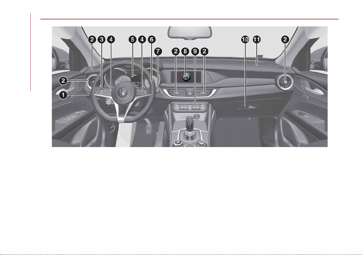
INSTRUMENTPANEL
KNOWING YOUR CAR
1
1. Light switch; 2. Air diffusers; 3. Left stalk; 4. Controls on the steering wheel; 5. Instrument panel; 6. Steering
wheel; 7. Right stalk; 8. Connect; 9. Automatic dual-zone climate control system; 10. Glove compartment; 11. Passenger
side airbag.
03036V0001EM
10
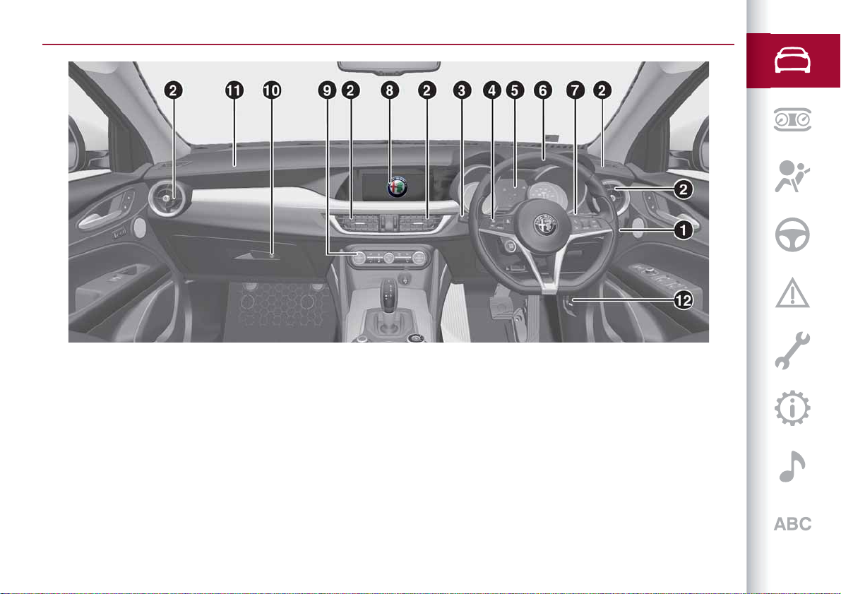
DASHBOARD FOR RIGHT-HAND DRIVE VERSION
2
03036V0004EM
1. Light switch; 2. Air diffusers; 3. Left stalk; 4. Controls on the steering wheel; 5. Instrument panel; 6. Steering
wheel; 7. Right stalk; 8. Connect; 9. Automatic dual-zone climate control system; 10. Glove compartment; 11. Passenger
side air bag; 12. Bonnet release lever.
11
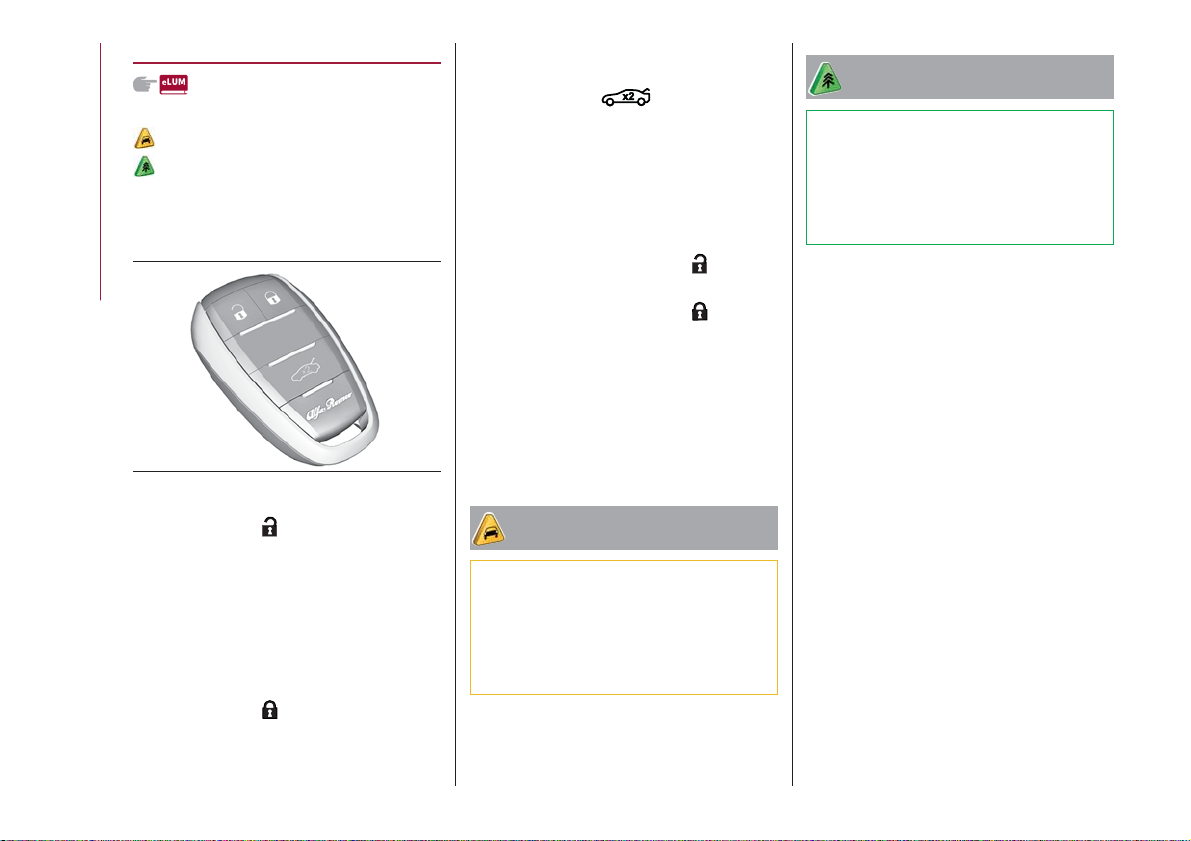
THE KEYS
ELECTRONIC KEY
1)
1)
The car is equipped with two electronic
keys with the Keyless Start
fig. 3 function.
KNOWING YOUR CAR
3
04016S0010EM
direction indicators (if activated from
Connect system).
Rapidly press the
button twice to
open the tailgate remotely. The direction
indicators will flash twice to indicate that
the tailgate has been opened.
Automatic window opening/closing
function
(where provided)
Prolonged pressing of button
: all
windows open.
Prolonged pressing of button
: all
windows closed.
REQUESTFOR ADDITIONAL KEYS
If you need a new electronic key, go to an
Alfa Romeo Dealership, taking an ID
document and the car ownership
documents.
IMPORTANT
1) Used batteries may be harmful to the
environment if not disposed of correctly.
They must be disposed of as specified by law
in the special containers or taken to an Alfa
Romeo Dealership, which will take care of
their disposal.
Briefly press the
button: unlocking of
doors and tailgate, timed switching-on of
internal lights and single flashing of
direction indicators (if activated from the
Connect system).
The doors can always be unlocked by
putting the metal insert inside the driver
side door lock.
Briefly press the
button: locking of
doors and tailgate, timed switching-off of
internal lights and double flashing of
12
IMPORTANT
1) The electronic components inside the key
may be damaged if the key is subjected to
strong shocks. In order to ensure complete
efficiency of the electronic devices inside the
key, it should never be exposed to direct
sunlight.
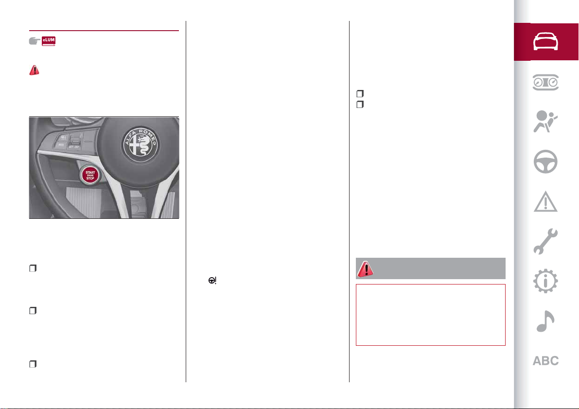
IGNITION DEVICE
OPERATION
1) 2) 3) 4) 5)
To activate the starter switch fig. 4, the
electronic key must be inside the
passenger compartment.
4
The ignition device has the following
possible states:
STOP: engine off, steering locked.
Some electrical devices (e.g. central door
locking system, alarm, etc.) are still
available;
ON (single button press): all electrical
devices are available. This state can be
selected by pressing the ignition device
button once, without pressing the brake
pedal;
AVV: engine starting. This state can be
selected by pressing the starter button
04026V0001EM
once with the brake pedal pressed.
NOTE With the starter switch ON, if
30 minutes pass with P (Park) mode
engaged and the engine stopped, the
starter switch will automatically move to
the STOP position.
NOTE With the engine running, it is
possible to go away from the car taking
the electronic key with you. The engine
will still be running. The vehicle will
indicate the absence of the key on board
when the door is closed.
For more information on the engine
start-up, see the description in the
"Starting the engine" paragraph, in the
"Starting and driving" chapter.
IMPORTANT If the battery was
disconnected, do not start the engine
immediately after reconnecting the
terminals, but press the start button,
without operating the pedals, to turn on
the instrument panel and then start the
engine.
The
symbol on the instrument panel
will remain on, indicating that the
steering must be initialised. To do this,
turn the steering wheel from one end to
the other and bring it back to the centre
position within 30 seconds from starting
the engine. If any red warning lights on
the instrument panel remain lit, stop the
engine, wait for at least 5 seconds and
repeat the starting procedure described
above.
STARTING WITH FLATKEY BATTERY
If the remote control battery is flat,
proceed as follows to start the vehicle:
lift the front armrest;
lay the key over the profile at the
bottom of the compartment.
STEERING LOCK
(where provided)
Activation
The steering lock is engaged when the
driver door is opened with the ignition
device button at STOP.
Deactivation
The steering lock disengages when the
ignition device is pressed and the
electronic key is recognised.
WARNING
1) Always take the key with you when you
leave your vehicle to prevent someone from
accidentally operating the controls.
Remember to engage the electric parking
brake. Never leave children unattended in
the vehicle.
13
2) It is absolutely forbidden to carry out any
after-market operation involving steering
system or steering column modifications
(e.g. installation of anti-theft device) that
could adversely affect performance,
invalidate the warranty, cause SERIOUS
SAFETY PROBLEMS and also result in the
car not meeting type-approval
requirements.
3) Before leaving the vehicle, ALWAYS
engage the handbrake. On versions
equipped with automatic transmission,
activate mode P (Park) and press the ignition
device to set it to STOP. When leaving the
KNOWING YOUR CAR
vehicle, always lock all the doors by pressing
the button on the handle.
4) For versions equipped with the Keyless
Start system, do not leave the electronic key
inside or near the car or in a place accessible
to children. Do not leave the vehicle with the
ignition device in ON position. A child could
activate the electric window winders, other
controls or even start the vehicle.
5) If the ignition device has been tampered
with (e.g. an attempted theft), have it
checked over by the Alfa Romeo Dealership
before driving again.
ENGINE IMMOBILIZER
The Engine Immobilizer system prevents
unauthorised use of the vehicle
preventing to start the engine.
The system does not need to be
enabled/activated: operation is
automatic, regardless of the fact that the
vehicle's doors are locked or unlocked.
When the ignition device is set to ON, the
Engine Immobilizer system identifies the
code transmitted by the key. If the code
is recognised as valid, the Engine
Immobilizer system enables engine
starting.
When the ignition device is brought back
to STOP, the Engine Immobilizer system
deactivates the control unit controlling
the engine, thus preventing its starting.
For the correct engine starting
procedures, see the instructions in the
"Starting the engine" paragraph,
"Starting and driving" chapter.
Irregular operation
If, during starting, the key code is not
correctly recognised, the
icon is
displayed on the instrument panel (see
the instructions in the "Warning lights and
messages" paragraph, "Knowing the
instrument panel" chapter). This
condition leads to the engine switching
off after 2 seconds. In this case, bring the
ignition device to STOP and then to ON; if
it is still blocked, try with the other keys
provided. If it is still not possible to start
the engine, contact an Alfa Romeo
Dealership.
If the
icon is displayed while driving,
this means that the system is running a
self-diagnosis (e.g. due to a voltage drop).
If the display persists, contact an Alfa
Romeo Dealership.
14

ALARM
(where provided)
Activation of the alarm triggers the
acoustic warning and the direction
indicators.
IMPORTANT The alarm is adapted to
meet requirements in various countries.
SWITCHINGON THE ALARM
With the doors, bonnet and tailgate
closed and the ignition device turned to
STOP, point the electronic key towards
the vehicle and press and release button
.
Except on some versions for specific
markets, the system produces a visual
and acoustic warning and enables door
locking.
With the alarm on, the warning lights on
the front door handle trims flash fig. 5.
5
04046V0001EM
TURNING THE ALARM OFF
Press the button.
IMPORTANT The alarm does not switch
off when the central opening is activated
using the metal insert in the key.
DISABLINGTHE ALARM
To completely disable the alarm (e.g.
during a long period of car inactivity), lock
the doors by turning the metal insert,
found inside the electronic key, in the
door lock.
DOORS
LOCKING/UNLOCKING DOORS FROM
THE INSIDE
Central locking/unlocking
If all doors are closed properly, they will
automatically be locked once the vehicle
has exceeded approximately 12 mph
(20 km/h) ("Auto relock" function active).
Press the
passenger side or rear (where provided)
door panel trims fig. 6 to lock the doors.
With doors locked, press the
on the front door panel trims to unlock
them.
button on the driver side,
button
6
04056V0001EM
15
LOCKING/UNLOCKING DOORS FROM
THE OUTSIDE
Locking from the outside
With the doors closed, press the
button on the key.
In any case, the doors can be locked with
all the doors closed and the tailgate open.
When the button
on the key is
pressed, all the locks are closed, including
that of the open tailgate. The latter will
be locked when it is closed.
KNOWING YOUR CAR
2)
Door unlocking from the outside
Press button
on the key.
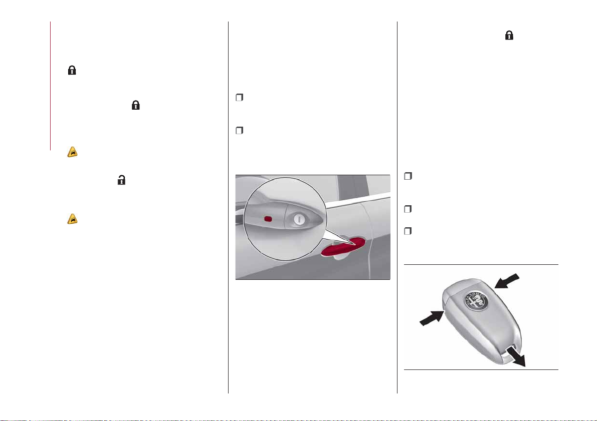
PASSIVE ENTRY
(where provided)
3)
The Passive Entry system can identify
the presence of an electronic key near
the doors and the tailgate.
The system enables the doors (or the
tailgate) to be locked/unlocked without
pressing any buttons on the electronic
key.
The key is detected only after the system
recognizes the presence of a hand in one
of the front handles. If the detected key
is valid, the doors and the tailgate are
unlocked (the elements that open depend
on the Connect system settings).
Where the function is provided, grasping
the handle of the driver's door unlocks
the driver's door only, or all the doors,
depending on the mode set in the
Connect system.
Door locking
To lock the doors, proceed as follows:
make sure that you have the
electronic key and are close to the driver
or passenger side door handle;
press the "door lock" button fig. 7 on
the handle: this will lock all the doors and
the tailgate. Door locking will activate the
alarm as well (where provided).
7
04056S0003EM
IMPORTANT After pressing the "door
locking" button, you need to wait two
seconds before the doors can be
unlocked again using the door handle. It is
therefore possible to check whether the
vehicle is locked correctly by pulling the
door handle within 2 seconds. The doors
will not be unlocked again.
The car doors and tailgate can be locked
in any case by pressing the
button on
the electronic key or on the car’s inner
door panel.
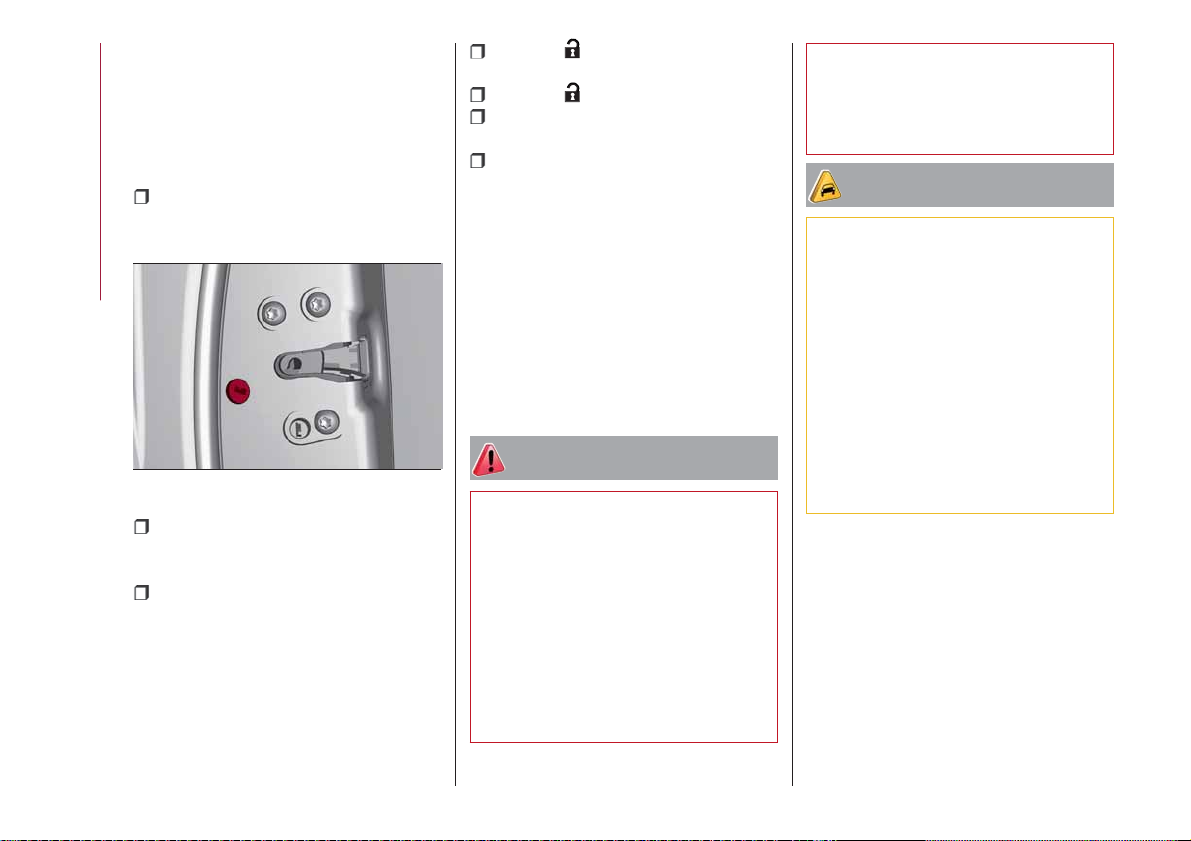
Driver side door emergency opening
If the electronic key does not work, e.g.
because its battery is flat or the vehicle
battery is flat, the emergency metal
insert inside the key can anyway be used
to operate the lock, unlocking the driver
side door.
To extract the metal insert, proceed as
follows:
Pressing in the points indicated in
fig. 8 extract the cover pulling
downwards;
remove the key insert from its housing
fig. 9;
insert the metal insert in the driver
side door lock and turn it to unlock the
door.
8
04016S0002EM
16
9
04016S0003EM
Do not simultaneously push the
lock/unlock door button fig. 7 and pull the
handle, (see fig. 10 ).
10
04056S0004EM
POWER LOCK
(where provided)
6)
This safety device inhibits the operation
of the interior door handles and the door
locking/unlocking button.
It thereby prevents the opening of the
doors from inside the passenger
compartment, serving as an obstacle to
break-in attempts (e.g. broken window).
We recommend that you activate the
device each time you park your vehicle.
Activating the device
The device is enabled on all the doors by
pressing the
button on the key twice
quickly.
The direction indicators flash 3 times to
let you know that the device is active.
If one or more of the doors are not closed
correctly, the device will not activate,
thus preventing a person from getting
stuck inside the passenger compartment
by entering the vehicle through, and then
closing, the open door.
Deactivating the device
The device disengages automatically:
when the doors are unlocked (pressing
button
on the key with remote
control);
when the ignition device is set to ON.
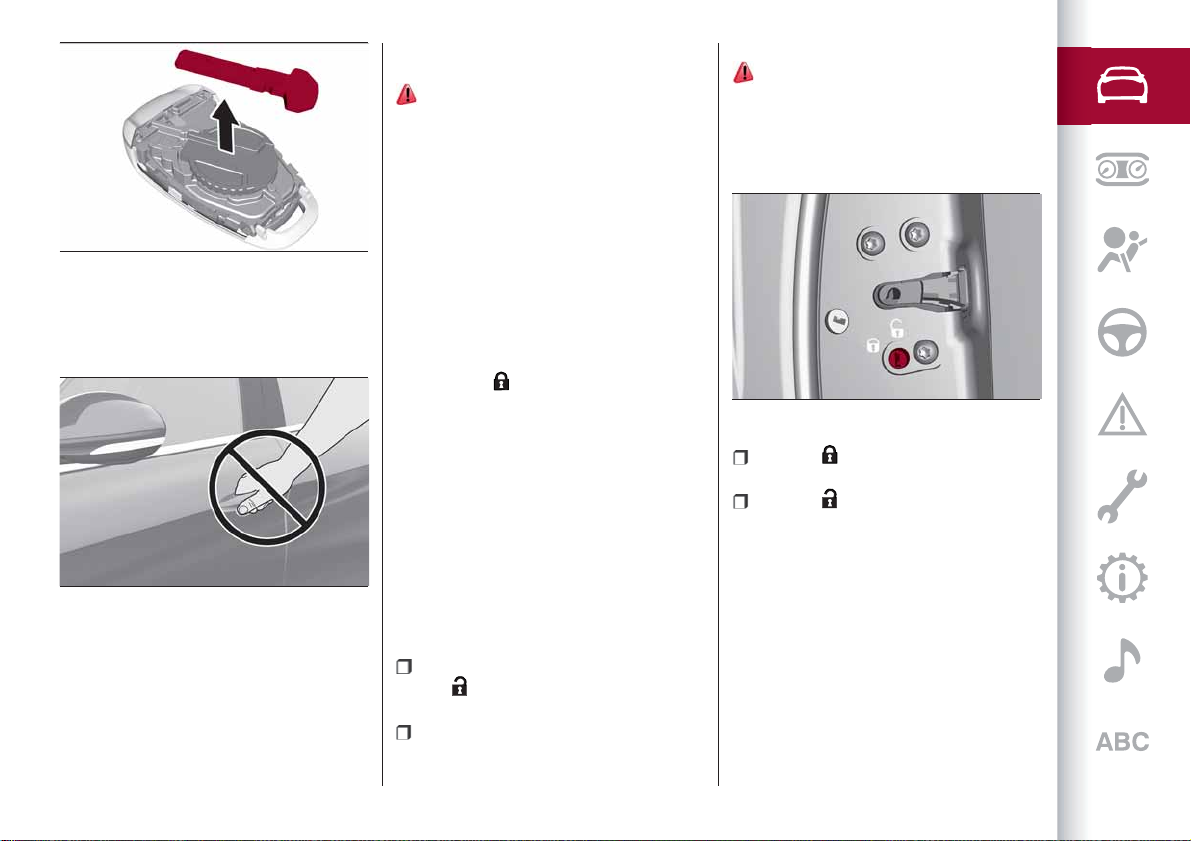
CHILD SAFETY DEVICE
7) 8)
This system prevents the rear doors from
being opened from the inside.
This device fig. 11 can be engaged only
with the doors open:
11
04056S0007EM
position : device engaged (door
locked);
position : device not engaged (door
may be opened from the inside).
The device remains engaged even if the
doors are electrically unlocked.
IMPORTANT The rear doors cannot be
opened from the inside when the child
safety device is engaged.
17
UNLOCKINGTHE DOORS WITH A FLAT
BATTERY
Proceed as follows to unlock the doors if
the car battery is flat.
Rear doors and passenger door
Proceed as follows:
insert the metal insert of the
electronic key in the release device
housing fig. 12;
KNOWING YOUR CAR
12
turn the key clockwise for the right
door locks or anticlockwise for the left
door locks;
remove the key from the housing.
Proceed in one of the following ways to
realign the door lock device (only when
the battery charge has been restored):
04056S0008EM
press the button on the electronic
key;
press the button on the door panel;
open by inserting the key insert in the
driver's door lock;
operate the internal door handle.
IMPORTANT For the rear doors, if the
child lock device was engaged and the
previously described locking procedure
carried out, operating the internal handle
will not open the door but will only realign
the lock release device. To open the door,
the outside handle must be used. The
door central locking/unlocking buttons
are not deactivated when the emergency
lock is engaged.
WARNING
6) Once the Power Lock system is engaged,
it is impossible to open the doors from inside
the vehicle. Before getting out of the car,
please therefore check that there is no-one
left inside.
7) NEVER leave children unattended inside
the car, let alone leave the car with the doors
unlocked in a place that children can access
easily. Children may seriously, or even
fatally, injure themselves. Also ensure that
children do not inadvertently operate the
electric parking brake, the brake pedal or the
transmission lever.
8) Always use this device when carrying
children. After engaging the child lock on
both rear doors, check for effective
engagement by trying to open a door with
the internal handle.
IMPORTANT
2) Make sure to take the key with you once a
door or the tailgate is locked, to prevent
locking the same key inside the vehicle. If the
key has been locked in, it can only be
recovered using the second provided key.
3) The operation of the recognition system
depends on various factors, such as, for
example, any electromagnetic wave
interference from external sources (e.g.
mobile phones), the charge of the battery in
the electronic key and the presence of metal
objects near the key or the car. In these
cases it is still possible to unlock the doors
by using the metal insert in the electronic key
(see description on the following pages).
18
SEATS
FRONT SEATS WITH MANUAL
ADJUSTMENT
9)
4)
Longitudinal adjustment
10)
Lift lever 1 fig. 13 and push the seat
forwards or backwards.
13
IMPORTANT Carry out the adjustment
while sitting on the seat involved (driver
side or passenger side).
Height adjustment
Adjust lever 2 fig. 13 upwards or
downwards to obtain the required height.
04066V0001EM
IMPORTANT Carry out the adjustment
while sitting on the seat involved (driver
side or passenger side).
Backrest angle adjustment
Move lever 3 fig. 13 to adjust the
backrest angle, accompanying it with the
movement of the torso (operate the lever
until the desired position is reached, then
release it).
Folding the backrest forward
(where provided)
The front passenger seat can be folded
forward by operating lever 3 fig. 13.
During this operation, accompany the
backrest down with your free hand.
Folding the backrest down further
increases the size of the load
compartment.
"SPARCO" SPORT CARBONSHELL
SEATS
(where provided)
Longitudinal adjustment
Lift lever 1 fig. 14 and push the seat
forwards or backwards.
14
04066S0002EM
IMPORTANT Carry out the adjustment
while sitting on the seat involved (driver
side or passenger side).
Height adjustment
(electric)
Move button 2 fig. 14 upwards or
downwards to obtain the required height.
Backrest angle adjustment
Move lever 3 fig. 14 to adjust the
backrest angle, accompanying it with the
movement of the torso (operate the lever
until the desired position is reached, then
release it).
19

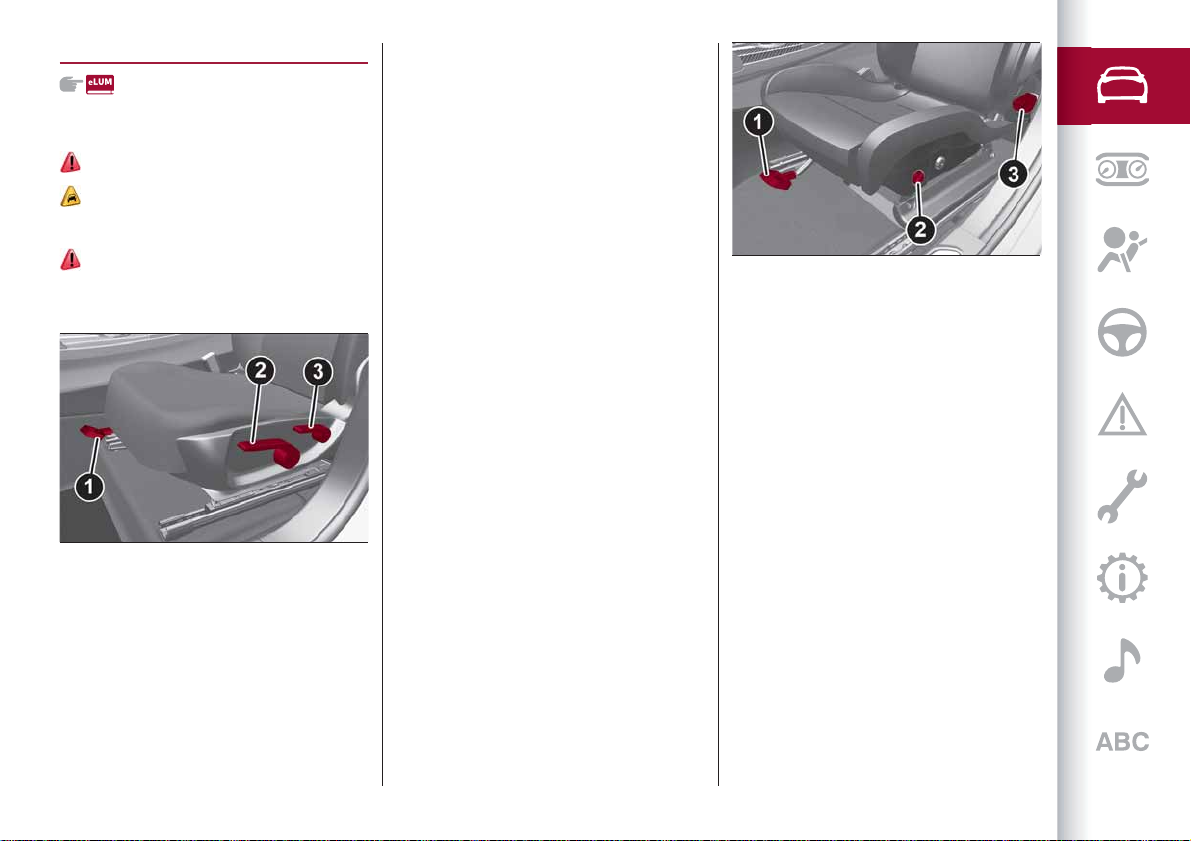
ELECTRICALLYADJUSTABLE FRONT
SEATS
5)
NOTE The conformation of the seats may
vary according to the versions.
The buttons for electrical seat
adjustment are on the outer side of the
seat, near the floor.
These buttons can be used to adjust the
height, the lengthwise position in relation
to the vehicle and the angle of the
KNOWING YOUR CAR
backrest.
15
Height adjustment
Use the rear part of switch 1 fig. 15 to
modify the height and/or the angle of the
seat cushion.
Longitudinal adjustment
Push switch 1 forwards or backwards to
move the seat in the corresponding
direction.
04066V0003EM
Backrest angle adjustment
Push switch 2 fig. 15 forwards or
backwards to adjust the backrest in the
corresponding direction.
Electric lumbar adjustment
Use the joystick 3 fig. 15 to actuate the
lumbar area device until getting top
comfort while driving.
Press the following parts of the joystick:
top: inflates the cushion;
bottom: deflates the cushion;
front: inflates the upper part of the
cushion;
rear: inflates the lower part of the
cushion.
IMPORTANT The electrical adjustment is
only allowed when the ignition device is
turned to ON and for about 2 minutes
after it is turned to STOP.The seat can
also be moved after opening/closing the
door for about 2 minutes; car
locking/unlocking or switching on of the
centre front ceiling light.
Seat angle adjustment (tilting)
(where provided)
The seat angle can be set to four
positions. Lift or push the front part of
control 1 to move the front part of the
seat in the corresponding direction.
Release control 1 when the seat has
reached the desired position.
Backrest width adjustment
(where provided)
Push the switches 4 fig. 15 to regulate
the width of the backrest through the
lateral paddings.
Storing the driver’s seat positions
Buttons 5 fig. 16 allow you to store and
recall three different driver’s seat
positions.
You can store and recall for 20 minutes
with the starter switch in the STOP
position or with the starter switch in the
ON position, the engine running and the
vehicle moving. The performed position
memorisation is confirmed by an acoustic
warning.
16
04066V0015EM
To memorise a seat position, adjust it
with the various controls, then press the
button where you want to memorise the
position for 1.5 seconds. When a new
seat position is memorised, the
20

previously memorised position on the
same button is automatically
overwritten.
Recalling a memorised position is also
possible for about 3 minutes after the
doors are opened and about 1 minute
after the engine is stopped. To recall a
memorised position, press the relevant
button briefly.
EASYENTRY FUNCTION
The Easy Entry function is designed to
retract the driver side seat automatically
by 2.36 in (60 mm) to make it easier for
the driver to get in and out of the car.
The movement is activated only if the
seat is set to a driving position which is in
front of the B pillar of the car.
The function is associated with
electrically adjustable front seats for
each of the three stored positions.
The Easy Entry function can be
activated/deactivated using the Connect
system.
Activating entrance mode
With the door open and the starter device
at STOP, the driver side seat will be in a
position retracted by 2.36 in (60 mm)
with respect to the driving position set by
the user.
When the door is closed and the starter
device is in the ON position, the seat will
automatically return to the set driving
position.
NOTE If the seat is moved manually while
it is still in retracted position, it will
remain in the new set position when the
car is entered again.
Activating exit mode
In order to help the driver get out of the
car, the driver side seat will move back by
2.36 in (60 mm) when the starter device
is in STOP mode and the driver side door
is opened.
NOTE Pressing any button on the seat
memory or control panel will immediately
interrupt the automatic positioning
function (antipanic function). The
operation must be repeated to complete
the function.
REAR SEATS
11)
The rear seats allow for:
three passengers.
17
04066V0005EM
SPLIT FOLDING REAR SEAT
Partial extension of the luggage
compartment (1/3 or 2/3)
6)
Extending the right side of the luggage
compartment (1/3 of the rear seat)
allows you to carry two passengers on
the left part of the rear seat, while
extending the left side (2/3 of the rear
seat) allows you to carry one passenger.
Proceed as follows:
completely lower the rear seat head
restraints;
place the seat belt so that it doesn't
impede the movement of the backrest
while tilting it;
operate the left-hand lever 1
fig. 18 (inside the luggage compartment)
to fold down the left side, or the mirror
image right-hand lever to fold down the
right side of the backrest. It will fold
21
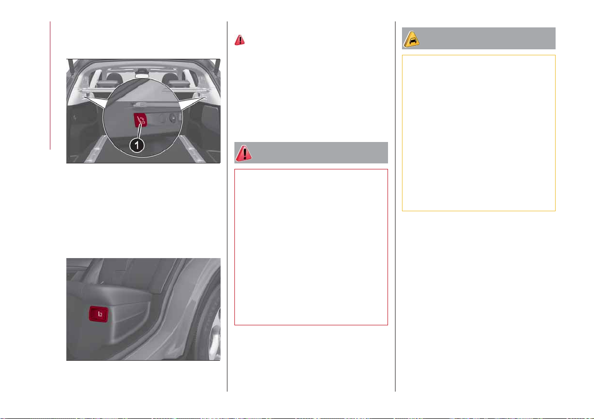
forwards automatically. If necessary,
accompany the backrest during the initial
stage of tilting.
KNOWING YOUR CAR
18
It is also possible to disengage sections
of the rear seat from inside the luggage
compartment using one of the two levers
located under the rear seat fig. 19. Each
lever folds down the section of the
backrest on the same side.
04066V0009EM
Repositioning the backrests
12)
Move the seatbelts to the side, making
sure that they are correctly extended and
not twisted and that they are not trapped
behind the backrests of the seats, then
lift the backrests pushing them back until
you hear the locking click on both
attachment mechanisms.
WARNING
9) All adjustments must be made with the
car stationary.
10) Once you have released the adjustment
lever, always check that the seat is locked on
the guides by trying to move it back and
forth. If the seat is not locked into place, it
may unexpectedly slide and cause the driver
to lose control of the car.
11) Always make sure that all those on
board the car are seated and are wearing
their seat belts correctly.
12) Make sure the backrests are properly
secured at both sides to prevent them from
moving forward, in the event of sharp
braking, with possible impact with of the
passengers.
IMPORTANT
4) The fabric upholstery of the seats has
been designed to withstand long-term wear
deriving from normal use of the car. Some
precautions are however required. Avoid
prolonged and/or excessive rubbing against
clothing accessories such as metal buckles
and Velcro strips which, by applying a high
pressure on the fabric in a small area, could
cause it to break, thereby damaging the
upholstery.
5) Do not place any kind of items under the
electrically adjusted seats as they could
impede their movement or otherwise
damage the controls.
6) Before tilting the backrest, remove any
objects on the seat cushion.
19
22
04066V0007EM

HEAD RESTRAINTS
ADJUSTMENTS
13)
Upward adjustment: raise the head
restraint until it clicks into place.
Downward adjustment: press button 1
fig. 20 and lower the head restraint.
20
HEAD RESTRAINTS (removal)
Proceed as follows to remove the head
restraints:
raise the head restraints to their
maximum height;
press button 1 to lift the head
restraint, then press device 2 fig. 19 (front
head restraint) or 1 and 2 fig. 21 (rear
head restraint) to remove it.
04076V0001EM
21
04076V0002EM
WARNING
13) Head restraints must be adjusted so
that the head, rather than the neck, rests on
them. Only in this case they can protect your
head correctly. Any removed head restraints
must be repositioned correctly, in order to
protect the occupants in the event of impact:
follow the instructions above.
STEERINGWHEEL
14) 15)
ADJUSTMENTS
The steering wheel can be adjusted both
in height and in depth.
22
04086V0001EM
23
To adjust the position bring the lever 1
fig. 22 down to position A, after which the
steering wheel can be adjusted to the
most suitable position and subsequently
locked in this position by bringing lever
1 to position B again.
ELECTRIC STEERINGWHEEL HEATING
(where provided)
With ignition device at ON, press the
fig. 23 button on the air conditioner
control panel.
KNOWING YOUR CAR
WARNING
14) All adjustments must be carried out only
with the car stationary and engine stopped.
15) It is absolutely forbidden to carry out
any after-market operation involving
steering system or steering column
modifications (e.g. installation of anti-theft
device) that could adversely affect
performance, invalidate the warranty, cause
SERIOUS SAFETY PROBLEMS and also
result in the car not meeting type-approval
requirements.
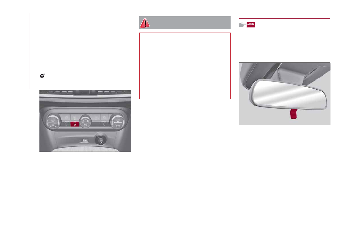
REAR VIEW MIRRORS
INTERIOR MIRROR
Operate lever fig. 24 to adjust the mirror
into two different positions: normal or
anti-glare.
23
04086V0002EM
When the function is enabled, the LED on
the button switches on.
IMPORTANT If this function is activated
with the engine stopped the battery may
run down.
24
24
04106S0001EM
The mirror is fitted with a safety device
that causes its release in the event of a
violent impact with the passenger.

ELECTROCHROMIC INTERIOR MIRROR
(where provided)
On some versions, an electrochromic
mirror is available, that can automatically
modify its reflecting action to prevent
dazzling the driver fig. 25.
The electrochromic mirror has an
ON/OFF button to activate/deactivate
the electrochromic anti-glaring function.
DOOR MIRRORS
16)
Electric adjustment
The mirrors can only be adjusted with the
ignition device at ON.
Select the desired mirror using device 1
fig. 26:
device in position A: left mirror
selected;
device in position B: right mirror
selected.
Manual folding
To fold the mirrors, move them from the
open position to the closed position
fig. 27.
27
04106V0005EM
Electric folding
(where provided)
With device 1 in position D, move it to
25
04106S0002EM
position C fig. 26. Turn the device 1 again
to position C to return the mirrors to the
driving position.
26
04106V0004EM
NOTE In case of involuntary movement of
the mirrors (following a crash) beyond the
To adjust the selected mirror, use device
1 in the four directions.
IMPORTANT Once adjustment is
complete, rotate device 1 to position D
to prevent accidental movements.
normal operating position, the system
will activated an auxiliary realignment
cycle when the first opening/closing
command is imparted. The mirror will
therefore return to the overtravel
position which was reached by accident,
will fold and then open to the correct
position.
If device 1 is turned again during door
25

mirror folding (from closed to open
position and vice versa), their movement
direction is reversed.
Automatic activation
Activating the central door locking
system from outside the car
automatically folds the mirrors, they
return to the driving position when the
ignition switch is turned to the ON
position.
If the external mirrors were folded
KNOWING YOUR CAR
operating on the device 1, they could be
returned to the driving position only
operating a new control on the device.
Activation/deactivation of the function
The electric mirror folding function can
be activated/deactivated using the
Connect system menu (the default
setting of the function is “Off”).
Alternatively, you can choose to
open/close the mirrors automatically
when opening/closing the doors (using
the electronic key or the Passive Entry
system, where provided).
IMPORTANT The mirrors must always be
open while driving and should never be
folded.
ELECTROCHROMIC EXTERIOR
MIRRORS
(where provided)
As well as an inside mirror, an
electrochromic mirror is also available on
some versions, which automatically
modifies its reflecting properties to
prevent dazzling the driver. The
anti-glare electrochromic enable/disable
button fig. 25 is the same for all rear view
mirrors.
WARNING
16) As door mirrors are curved, and
therefore they may slightly alter the
perception of distance.
EXTERNAL LIGHTS
LIGHT SWITCH
The light switch fig. 28, located on the
left side (left hand drive versions) or on
the right side (right hand drive versions)
of the dashboard, controls operation of
headlights, side lights, daytime running
lights, dipped beam headlights, front and
rear fog lights.
28
The external lights can be activated only
when the ignition device is in position ON,
except for the parking lights. See the
"Parking lights" paragraph, in this chapter
for more information.
The instrument panel and the various
controls on the dashboard will be lit up
when the exterior lights are switched on.
04126V0005EM
26
AUTOFUNCTION (Dusk sensor)
This is implemented by an infrared LED
sensor on the windscreen that works in
conjunction with the rain sensor. It is able
to detect variations in the outside light
level based on the light sensitivity set
through the Connect system.
The dusk sensor sensitivity can be
adjusted according to 3 levels: level
1=minimum sensitivity, level 2=average
sensitivity, level 3=maximum sensitivity.
The higher the sensitivity set, the lesser
is the external light variation needed to
switch the lights on (e.g. with a setting on
level 3 at sunset the headlights come on
earlier than levels 1 and 2).
Function activation
Turn the light switch to the
position.
IMPORTANT The function can only be
activated with the ignition device at ON.
Function deactivation
To deactivate the function, turn the light
switch to a position other than
.
DIPPED HEADLIGHTS
Turn the light switch to to switch on
the side lights, the lights on the
instrument panel and the dipped beam
headlights.
warning light switches on in the
The
instrument panel.
DAYTIME RUNNING LIGHTS (DRL) AND
SIDE LIGHTS (Daytime Running Lights)
(where provided)
17) 18)
With the ignition device turned to ON and
the light switch turned to position
the
daytime running lights are automatically
activated; the other lights and interior
lighting remain off.
Where provided, when the direction
indicators are activated, the
corresponding DRL will be dimmed (on
35W Bi-Xenon Headlamps, the DRL will
be turned off), until the direction
indicators are deactivated.
Where provided, the DRL can be
activated/deactivated from Connect
system, by selecting the following
functions in sequence on the main MENU:
"Settings", "Lights" and "Daytime Running
Lights".
IMPORTANT For markets where DRL use
is not required, these lights work as side
lights and they are switched on and off
jointly with the main beam headlights.
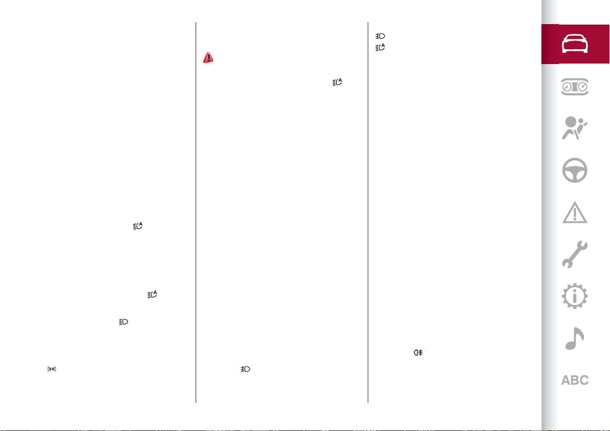
FRONT FOG LIGHTS
(where provided)
The fog light switch is integrated with the
light switch.
Press the
button to turn on the fog
lights with side lights and dipped beam
headlights on.
To turn off the fog lights, press the
button again or turn the switch to the
position.
The fog lights are switched on with the
dipped beam headlights or DRL on (the
latter work as side lights) and are
switched on when switching on the main
beam headlights but not when the main
beam headlights are flashed only.
If the fog lights are not switched off
before stopping the engine, the next time
the engine is started they will switch on
again.
Cornering lights
(where provided)
The fog lights perform cornering
function. This function allows to
illuminate the road or a corner better by
lighting the corresponding fog light.
The cornering function can be
deactivated on the Connect system by
selecting the following functions in
sequence on the main menu: "Settings",
"Lights" and "Cornering Lights".
REAR FOG LIGHT
The rear fog light switch is integrated
with the light switch.
Press the
button to switch the light
on/off.
The rear fog light switches on only when
the dipped beam headlights or fog lights
27

are switched on. The light can be
switched off by pressing the
again or by switching off the dipped
beam headlights.
When the engine is stopped with the rear
fog lights on, the next time the engine is
started the lights will, however, be off.
PARKING LIGHTS
They are switched on if, within a few
seconds from stopping the engine, the
light switch is put first in the
KNOWING YOUR CAR
and then the
switch on, if you want to leave only those
on one side (right/left) switched on, you
need to move the direction indicators
control on the position on the side you
wish to leave on.
When a front door is opened with the
light switch in position
heard to inform the driver that the
parking lights are on.
warning light switches on in the
The
instrument panel.
IMPORTANT Turning the ignition switch
to ON turns off the parking lights, which
were on only on one side.
HEADLIGHTS OFF TIMER
The "Follow Me" function delays the
switching off of the headlights after the
car has been stopped.
The function can be enabled from the
position. All side lights
, a tone will be
button
position
Connect system by selecting the
following functions from the main menu
in sequence: "Settings", "Lights" and
"Follow me"; the side lights and the
dipped beam headlights stay on for a
time that can be set between 30, 60 and
90 seconds.
Function activation
With the headlights on, take the ignition
device to the STOP position: the timer
starts when the light switch is turned to
position.
the
IMPORTANT To activate this function the
headlights must be deactivated within
2 minutes after the ignition device has
been taken to STOP.
Function deactivation
This function is deactivated by switching
on the headlights, the side lights or
bringing the ignition device to ON.
AFS FUNCTION (Adaptive Frontlight
System)
(where provided)
This is a system combined with Xenon
headlights (Bi-Xenon Headlamps 35W
version) which directs the main light
beam, horizontally and vertically, and
continuously and automatically adapts it
to the driving conditions round
bends/when cornering.
The system directs the light beam to light
up the road in the best way, taking into
account the speed of the car, the
bend/corner angle and the speed of
steering.
MAIN BEAM HEADLIGHTS
To activate the fixed main beam
headlights push the left lever towards
the instrument panel fig. 29. The light
switch must be turned to
With main beam headlights on, the
warning light/icon on the instrument
panel will come on at the same time.
29
The main beam headlights are switched
off by pushing the left stalk forward
again. Warning light/icon
in the instrument panel.
Flashing the headlights
The flashing of the main beam headlights
is activated by pulling the left stalk
or .
04126S0020EM
switches off
28
 Loading...