

Page 1

OWNER’S MANUAL
ALFA
Page 2

This Owner Handbook describes all the versions of the Alfa Spider, so you should only consider
the information concerning the trim level, engine and version purchased by you.
Dear Customer,
thank you for choosing Alfa Romeo.
Your Alfa Spider has been designed to guarantee the safety, comfort and driving pleasure typical of
Alfa Romeo.
This booklet will help you to get to know the characteristics and operation of your car.
The following pages contain all the indications necessary for you to be able to maintain the high standards
of performance, quality, safety and respect for the environment which characterise this Alfa Spider.
The enclosed Warranty Booklet also contains the regulations, the warranty certificate and a guide to the
services offered by Alfa Romeo.
Services which are essential and precious because, when you purchase an Alfa Romeo you are not only
acquiring a car, but the tranquillity that comes from knowing that an efficient, willing and widespread
organization is at your service for any assistance problems you may have.
Enjoy the reading. And have a good trip.
Page 3

MUST BE READ!
REFUELLING
Petrol engines: only refuel with unleaded petrol with octane rating (RON) not less than 95.
Diesel engines: only refuel with diesel fuel conforming to the European specification EN590. The use of
other products or mixtures may irreparably damage the engine with invalidation of the warranty due to the
damage caused.
K
ENGINE STARTING
Petrol engines: ensure that the handbrake is up, fully press the clutch pedal, without pressing the accelerator, put
the gear lever neutral, fit the electronic key into the ignition device to stop limit, briefly press the START/STOP but-
ton.
Diesel engines: ensure that the handbrake is up, fully press the clutch pedal, without pressing the accelerator, put
the gear lever neutral, fit the electronic key down into the ignition device until it stops. The instrument panel warning
light
m
will turn on, wait for the warning light
m
to turn off. The hotter the engine is, the quicker this will happen,
briefly press the START/STOP button as soon as the warning light
m
turns on.
PARKING ON FLAMMABLE MATERIAL
While working, the catalyst develops a very high temperature. Do not park the car over grass, dry leaves, pine
needles or any other inflammable materials: risk of fire.
RESPECTING THE ENVIRONMENT
A system for continuously monitoring emission system components to ensure greater environmental protec-
tion is fitted in your car.
Page 4

ELECTRICAL ACCESSORIES
If, after buying the car, you decide to add electrical accessories (that will gradually drain the battery), contact Alfa Romeo Authorized Services. They can calculate the overall electrical requirement and check that the car’s electric system can support the required load.
쇵
CODE CARD
(for versions/markets, where provided)
Keep the code card in a safe place, not in the car.
SCHEDULED SERVICING
Correct maintenance of the car is essential for ensuring it stays in tip-top condition and safeguards its safety features, its environmental friendliness and low running costs for a long time to come.
THE OWNER’S HANDBOOK CONTAINS…
…information, tips and important warnings regarding the safe, correct driving of your car, and its maintenance. Pay particular attention to the symbols
"
(personal safety)
#
(environmental protection)
â
(car well-be-
ing).
Page 5

Any queries concerning servicing should be forwarded to the showroom from which the car was purchased, the subsidiary company or to our branch offices or any point of the Alfa Romeo Network.
Warranty Booklet
The Warranty Booklet is delivered together with every new car and contains the regulations tied to the services given by Alfa Romeo Services and to the warranty conditions.
Correctly carrying out the scheduled services specified by the manufacturer is the best way to maintain the performance, safety characteristics and low running costs of your car. It is also necessary to maintain warranty cover.
“Service” guide
This contains the Alfa Romeo Authorized Services. The services can be recognized by the presence of the Alfa Romeo
badge and logo.
The Alfa Romeo organization in Italy can be found in the telephone book under the letter “A” Alfa Romeo.
Not all the models described in this booklet are available in all countries. Only some of the fittings described in this
booklet are fitted as standard to the car. The list of available accessories should be requested from the Alfa Romeo
Dealers.
Page 6
THE SYMBOLS USED IN THIS BOOKLET
The symbols illustrated in these pages show the subjects which should,
in particular, be closely studied.
Warning: partially or fully ignoring
these rules may lead to serious injury.
This indicates the correct procedures
to be followed to prevent the car
from damaging the environment.
Warning: partially or fully ignoring
these rules may lead to serious damage
being caused to the car which, in some
circumstances, may cause forfeiture
of the warranty cover.
The texts, illustrations and specifications given in this booklet refer to the car at the time of going to press.
As part of our ongoing striving to improve our products, Alfa Romeo may introduce
technical changes during production, therefore
the specifications and fittings may be altered without prior notice.
For details on this subject, please apply to the manufacturer’s sales network.
PERSONAL
SAFETY
PROTECTING THE
ENVIRONMENT CAR SAFETY
Page 7

6
SAFETY
DEVICES
WARNING
LIGHTS AND
MESSAGES
IN AN
EMERGENCY
CAR
MAINTENANCE
TECHNICAL
SPECIFICATIONSINDEX
DASHBOARD
AND
CONTROLS
CORRECT USE
OF THE CAR
DDAASSHHBBOOAARRDDAANNDDCCOONNTTRROOLLS
S
CEILING LIGHTS ................................................ 74
CONTROLS....................................................... 76
INTERIOR FITTINGS............................................ 78
THE TOP .......................................................... 81
DOORS ........................................................... 90
POWER WINDOWS ........................................... 92
BOOT.............................................................. 94
BONNET .......................................................... 97
HEADLIGHTS..................................................... 98
ABS SYSTEM ................................................... 100
VDC SYSTEM ................................................... 102
EOBD SYSTEM ................................................. 106
SOUND SYSTEM ............................................... 106
ACCESSORIES PURCHASED BY THE OWNER .......... 107
INSTALLATION OF ELECTRIC/ELECTRONIC DEVICES 107
PARKING SENSORS ........................................... 108
TYRE PRESSURE MONITORING SYSTEM
(T.P.M.S.)........................................................ 111
AT THE FILLING STATION .................................... 114
PROTECTING THE ENVIRONMENT ........................ 116
DASHBOARD .................................................... 7
INSTRUMENT PANEL ......................................... 8
SYMBOLS ....................................................... 9
THE ALFA ROMEO CODE SYSTEM......................... 9
ELECTRONIC KEY .............................................. 11
ALARM ........................................................... 17
IGNITION DEVICE............................................... 19
INSTRUMENTS.................................................. 22
RECONFIGURABLE MULTIFUNCTION DISPLAY.......... 26
SEATS ............................................................ 41
HEAD RESTRAINTS............................................. 44
STEERING WHEEL ............................................. 44
REARVIEW MIRRORS ......................................... 45
CLIMATE CONTROL SYSTEM ............................... 48
MANUAL CLIMATE CONTROL SYSTEM ................... 50
AUTOMATIC TWO-ZONE CLIMATE
CONTROL SYSTEM ............................................ 53
ADDITIONAL HEATER ......................................... 63
EXTERNAL LIGHTS ............................................ 64
WINDOW WASHING ......................................... 67
CRUISE CONTROL ............................................. 71
Page 8
7
SAFETY
DEVICES
WARNING
LIGHTS AND
MESSAGES
IN AN
EMERGENCY
CAR
MAINTENANCE
TECHNICAL
SPECIFICATIONS
INDEX
DASHBOARD
AND
CONTROLS
CORRECT USE
OF THE CAR
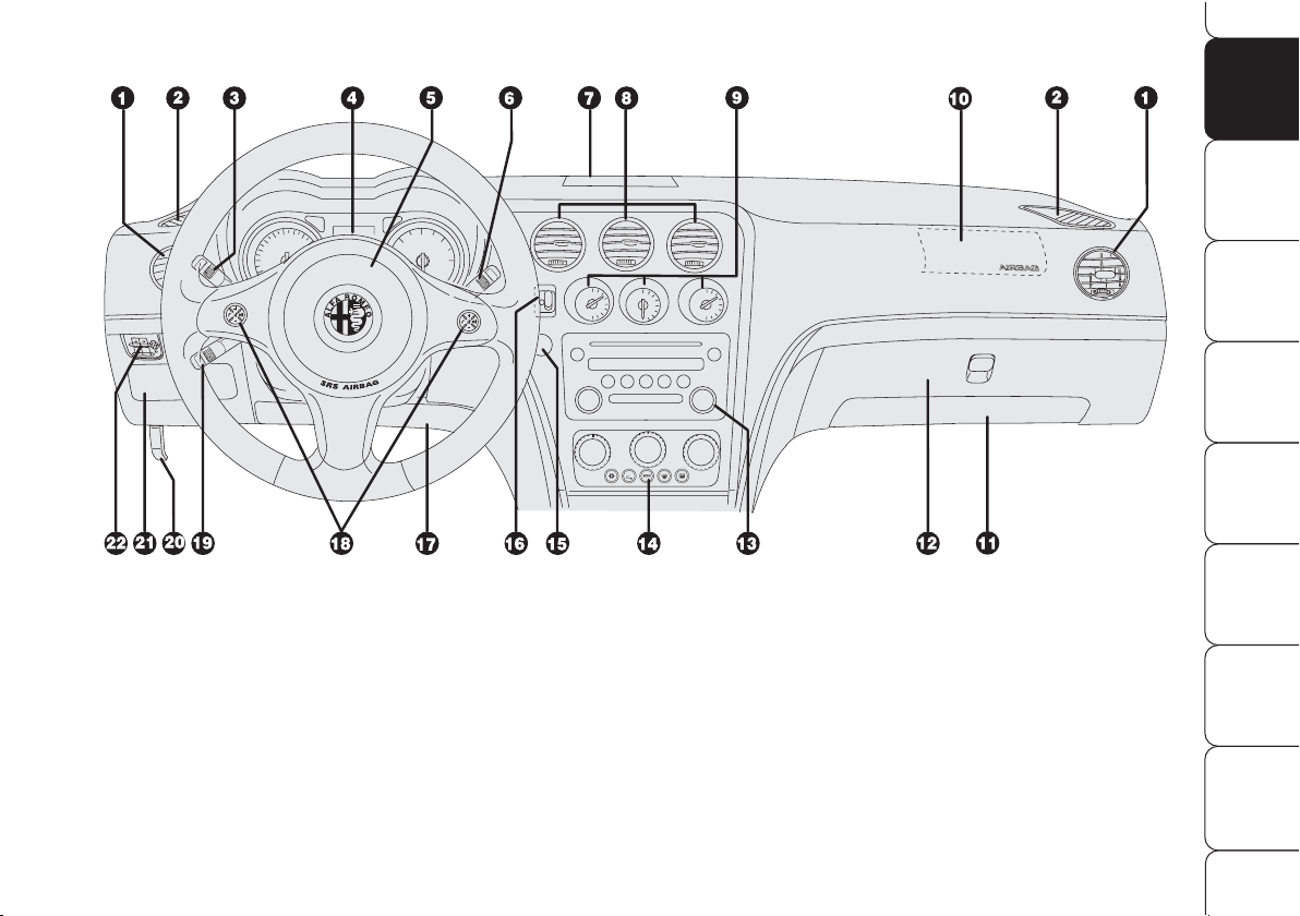
DASHBOARD
A0G0056m
fig. 1
1. Adjustable and swivel side air vents - 2. Front side window demisting/defrosting vents - 3. External lights control lever
4. Instrument panel - 5. Driver’s air bag and horn - 6. Windscreen wiper control lever - 7. Upper central vent
8. Adjustable and swivel central air vents - 9. Fuel level gauge/engine coolant temperature gauge/engine oil temperature
gauge (petrol versions) or turbocharger pressure gauge (diesel versions) - 10. Passenger’s air bag - 11. Passenger’s knees
air bag (where provided) - 12. Glove box - 13. Sound system - 14. Heating/ventilation/climate controls - 15. Engine
START/STOP button - 16. Ignition device - 17. Driver’s knees air bag - 18. Sound system controls on the steering
wheel (for versions/markets, where provided) - 19. Cruise Control lever (for versions/markets, where provided) - 20.
Bonnet opening lever - 21. Dashboard fusebox lid - 22. Switches for external lights, trip meter reset and headlamp aiming
device.
Page 9
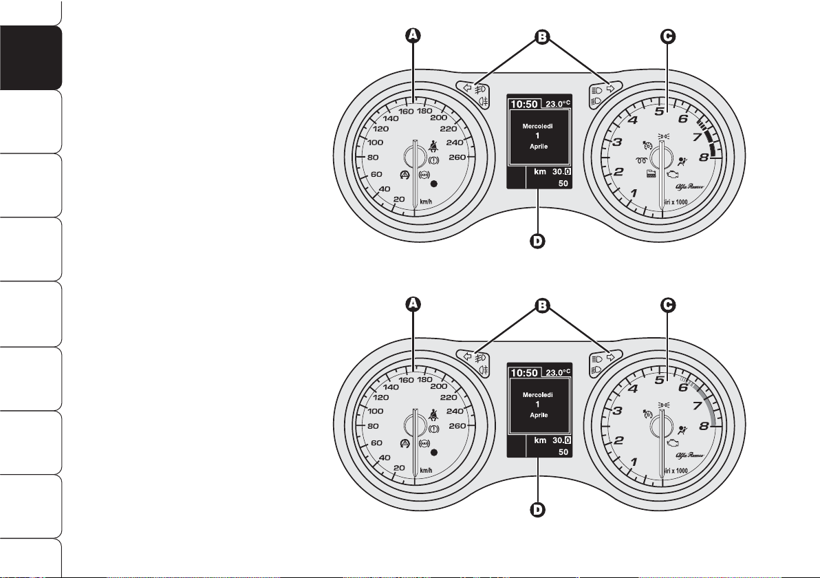
INSTRUMENT PANEL
A. Speedometer
B. Warning lights
C. Rev counter
D. Reconfigurable multifunction
display
cm
Warning lights on diesel
versions only
On diesel versions the rev counter
end scale value is at 6000 rpm.
8
SAFETY
DEVICES
WARNING
LIGHTS AND
MESSAGES
IN AN
EMERGENCY
CAR
MAINTENANCE
TECHNICAL
SPECIFICATIONSINDEX
DASHBOARD
AND
CONTROLS
CORRECT USE
OF THE CAR
Fig. 2
A0G0198m
fig. 2/a - 1750 TURBO BENZINA versions
A0G0331m
A. Speedometer
B. Warning lights
C. Rev counter
D. Reconfigurable multifunction
display
Page 10
THE ALFA ROMEO
CODE SYSTEM
To further protect you car from theft, it
has been fitted with an engine immobilising system. This system is automatically activated when the electronic
key is removed.
An electronic device, in fact, is fitted in
each electronic key grip. The device
transmits a radio-frequency signal when
the engine is started through a special
aerial built into the ignition switch on the
dashboard. The modulated signal, which
changes each time the engine is started, is the “password”, by means of
which the control unit recognises the
electronic key and enables to start the
engine.
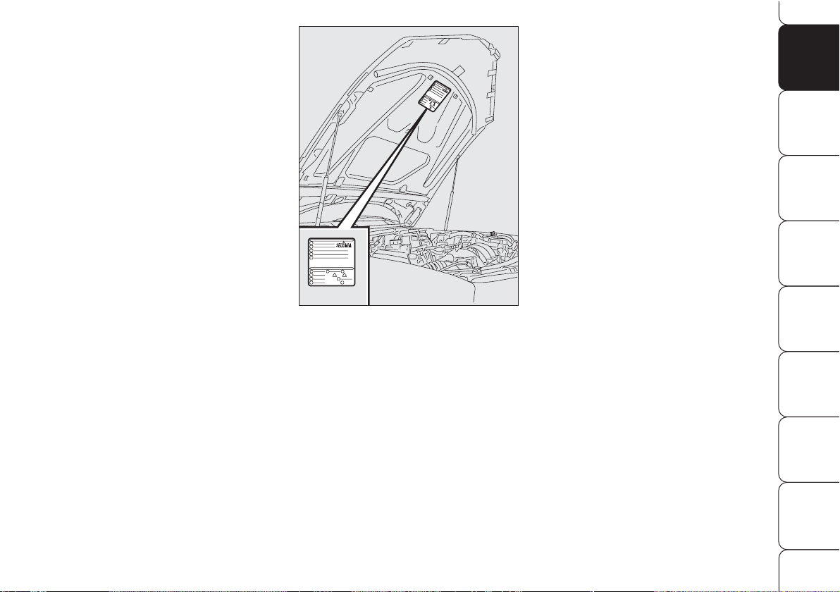
SYMBOLS
Special coloured labels have been attached near or actually on some of the
components of your car. These labels
bear symbols that remind you of the precautions to be taken as regards that particular component.
The plate summarising the symbols used
fig. 3 can be found under the bonnet.
9
SAFETY
DEVICES
WARNING
LIGHTS AND
MESSAGES
IN AN
EMERGENCY
CAR
MAINTENANCE
TECHNICAL
SPECIFICATIONS
INDEX
DASHBOARD
AND
CONTROLS
CORRECT USE
OF THE CAR
A0G0138m
fig. 3
Page 11
Message + symbol
Y
displaying when driving
If message + symbol
Y
are displayed
this means that the system is running
a self-test (for example for a voltage
drop).
If message + symbol
Y
continue to
stay on the display, contact Alfa Romeo
Authorized Services.
IMPORTANT Every electronic key has
its own code, which must be memorised
by the system control unit. To memorise
new keys, up to a maximum of eight,
apply solely to Alfa Romeo Authorized
Services taking with you all the keys in
your possession, the CODE card, a personal identity document and the car’s
possession documents. The codes of the
keys not provided during the new memorising procedure are erased from the
memory. This is to ensure that any lost
or stolen keys can no longer be used
to start the car.
OPERATION
Each time the electronic key is fitted into the ignition switch, the Alfa Romeo
CODE system control unit sends a recognition code to the engine control unit
to deactivate the inhibitor.
The code is sent only if the Alfa Romeo
CODE system control unit has recognised
the code transmitted from the electronic key.
If when fitting the electronic key into the
ignition device or starting engine the
code has not been recognised correctly, a message + symbol will be shown
on the display (see section “Warning
lights and messages”).
In this case, the electronic key should
be removed and refitted; if the lock continues, possibly try again with the other keys provided with the car. If it is still
not possible to start the car contact Alfa Romeo Authorized Services.
10
SAFETY
DEVICES
WARNING
LIGHTS AND
MESSAGES
IN AN
EMERGENCY
CAR
MAINTENANCE
TECHNICAL
SPECIFICATIONSINDEX
DASHBOARD
AND
CONTROLS
CORRECT USE
OF THE CAR
The electronic components inside the key may
be damaged if the key is
submitted to sharp knocks.
If 2 seconds after fitting
the electronic key into
the ignition switch the
message + symbol continue to
be displayed, this means that
the code of the keys has not
been memorised, thus the car is
not protected by the Alfa Romeo
CODE system against attempted theft. In this case, contact an
Alfa Romeo Authorized Service
to have the key codes memorised.
Page 12

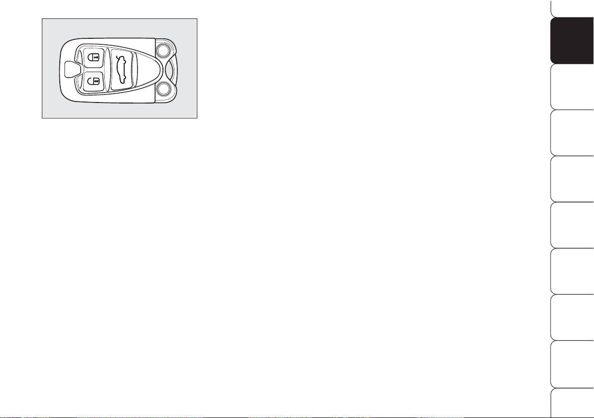
Button
Ë
operates central locking of
doors, and fuel lid with alarm deactivation (for versions/markets, where provided).
Button
`
shall be used to open the
tailgate.
After unlocking the doors by pressing
button
Ë
, if you do not open a door or
the tailgate within 2.5 minutes the system will lock again automatically all the
doors/tailgate.
When unlocking the doors, the driver’s
window will open slightly to facilitate
door opening. The driver’s window will
close automatically after about 3 minutes if the door is not opened. The driver’s window will reclose immediately if
the door is opened.
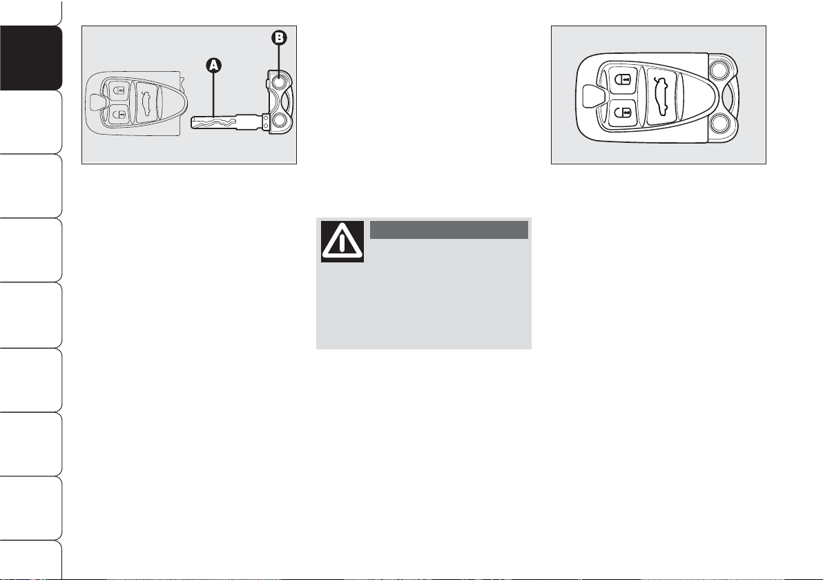
ELECTRONIC KEY fig. 5
The car is delivered with two copies of
the key with remote control.
The electronic key operates the ignition
switch.
Button
Á
operates central locking of
doors, tailgate and fuel lid with alarm
activation (for versions/markets, where
provided).
Locking the doors will obtain door mirrors folding (for versions/markets,
where provided); refitting the key will
reposition door mirrors automatically.
This function can be deactivated (see
paragraph “Rearview mirrors”).
ELECTRONIC KEY
CODE CARD
(for versions/markets, where provided)
The CODE card fig. 4, delivered with
the keys, contains the mechanical code
A and the electronic one B.
The code numbers on the CODE card must
be kept in a safe place, not in the car.
11
SAFETY
DEVICES
WARNING
LIGHTS AND
MESSAGES
IN AN
EMERGENCY
CAR
MAINTENANCE
TECHNICAL
SPECIFICATIONS
INDEX
DASHBOARD
AND
CONTROLS
CORRECT USE
OF THE CAR
A0G0023m
fig. 4
A0G0021m
fig. 5
If the car changes owner, the new owner must
be given the electronic
key and the CODE card.
Page 13
Replacing the battery
of the electronic key
If when pressing button
Ë,Á
, or
`
,
control given is refused or failing, the
battery should be replaced with an
equivalent one that can be purchased at
common stores.
To be sure that the battery is to be replaced, try again to press buttons
Ë
,
Á
, or
`
with another electronic key.
When closing the tailgate again, protection sensors are restored and direction indicators will flash once.
IMPORTANT Never expose the electronic key to direct sunlight: risk of damages.
IMPORTANT Remote control frequency may be disturbed by radio transmissions outside the car (e.g. mobile
phones, hams, etc…). In this event remote control may be failing.
The electronic key fig. 6 houses the
metal insert A, that can be extracted by
pressing button B.
The metal insert operates the following:
❒
central door locking/unlocking by
operating the driver’s door lock (with
flat car battery only the driver’s door
will open);
❒
windows opening/closing;
❒
switch (for versions/markets, where
provided) for deactivating the passenger’s air bag and knees air bag
(where provided);
❒
safe-lock device (for versions/markets, where provided);
❒
emergency unlocking of electronic
key from ignition switch.
12
SAFETY
DEVICES
WARNING
LIGHTS AND
MESSAGES
IN AN
EMERGENCY
CAR
MAINTENANCE
TECHNICAL
SPECIFICATIONSINDEX
DASHBOARD
AND
CONTROLS
CORRECT USE
OF THE CAR
A0G0022m
fig. 6
Never leave the elec-
tronic key unattended
to prevent anyone, especially
children, from holding it and
pressing button B-fig. 6. inadvertently.
WARNIN G
A0G0021m
fig. 7
Page 14
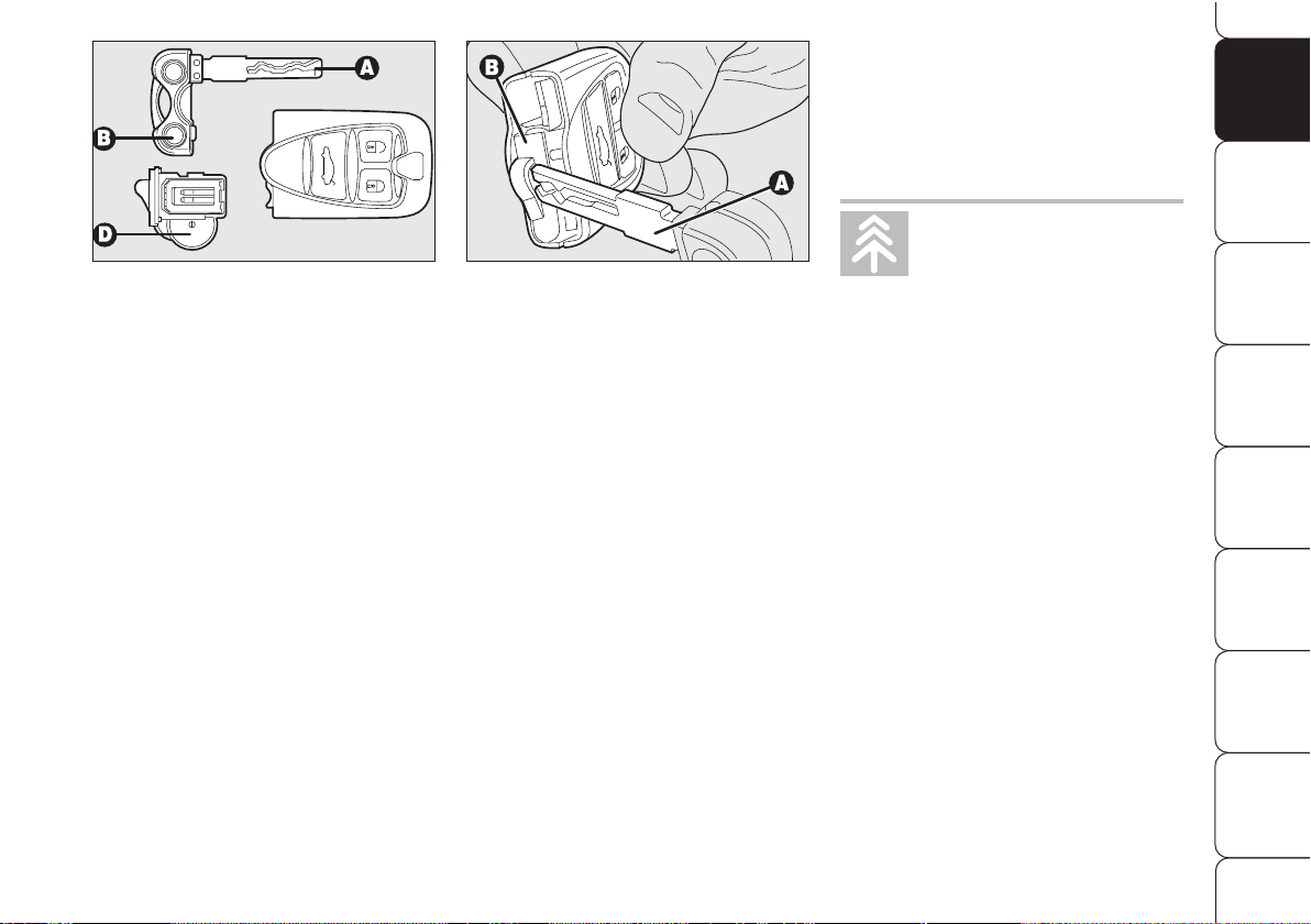
To change the battery fig. 8 proceed
as follows:
❒
take out the metal insert A by pressing button B;
❒
remove the snap-fitted case Bfig. 9 (red) by levering with the
metal insert A of the electronic key
in the point shown in the figure;
❒
remove the battery D-fig. 8 from
the case taking note of the bias (in
the figure the positive pole is facing
downwards);
❒
put the new battery into the case
with the correct bias;
❒
put the case down into its seat and
refit the metal insert.
13
SAFETY
DEVICES
WARNING
LIGHTS AND
MESSAGES
IN AN
EMERGENCY
CAR
MAINTENANCE
TECHNICAL
SPECIFICATIONS
INDEX
DASHBOARD
AND
CONTROLS
CORRECT USE
OF THE CAR
A0G0035m
fig. 8
A0G0242m
fig. 9
Used batteries are
harmful to the environ-
ment. They should be
disposed of as specified by law
in the special containers provided, or take them to Alfa
Romeo Authorized Services
which will deal with their disposal.
IMPORTANT Never touch the electric
contacts of the key and prevent fluid or
dust infiltration inside it.
Page 15
SAFE LOCK DEVICE
(for versions/markets, where provided)
This safety system inhibits the operation
of the car door handles.
The safe lock device represents top pro-
tection against break in attempts. Activate it each time you park the car.
14
SAFETY
DEVICES
WARNING
LIGHTS AND
MESSAGES
IN AN
EMERGENCY
CAR
MAINTENANCE
TECHNICAL
SPECIFICATIONSINDEX
DASHBOARD
AND
CONTROLS
CORRECT USE
OF THE CAR
Once the safe lock de-
vice has been actuated,
doors cannot be opened from
inside the car in any way
whatsoever. For this reason,
make sure there are no persons left inside the car.
WARNIN G
If the key battery is
flat, the safe lock device can only be deactivated by
unlocking the doors by turning
the metal insert of the electronic key into the driver’s
door lock or by fitting the electronic key into the ignition device.
WARNIN G
If the car battery is
down, the safe lock device can be activated only using the metal insert of the
electronic key on the driver’s
door revolving plug: in this
case the safe lock device is active on front passenger’s door.
WARNIN G
Page 16
15
SAFETY
DEVICES
WARNING
LIGHTS AND
MESSAGES
IN AN
EMERGENCY
CAR
MAINTENANCE
TECHNICAL
SPECIFICATIONS
INDEX
DASHBOARD
AND
CONTROLS
CORRECT USE
OF THE CAR
Device deactivation
The device is deactivated automatically
on every door in the following cases:
❒
when unlocking the doors;
❒
when unlocking only the driver’s
door (where possible);
❒
when fitting the electronic key into
the ignition switch.
Device activation is signalled by three
flashes of the led on the driver’s door
panel and, only if activated by pressing
the electronic key button
Á
, of direction
indicators.
Should one of the doors be not perfect-
ly closed, the safe lock device is not activated, thus preventing that a person
getting into the car from the open door
remains blocked inside the passenger’s
compartment when he/she closes the
door.
A0G0021m
fig. 10
Device activation
The device is automatically activated on
every door in the following cases:
❒
turning twice the metal insert of the
electronic key into the driver door to
locking position;
❒
pressing twice the electronic key button
Á
.
Page 17

16
SAFETY
DEVICES
WARNING
LIGHTS AND
MESSAGES
IN AN
EMERGENCY
CAR
MAINTENANCE
TECHNICAL
SPECIFICATIONSINDEX
DASHBOARD
AND
CONTROLS
CORRECT USE
OF THE CAR
The main functions that can be activated with the electronic key or with the emergency metals insert are the following:
(*) It is possible to set the option “Unlocking front door only” through the “Setup Menu” (see paragraph “Reconfigurable multifunction display” in this sec-
tion). In this case pressing button
Á
and turning the metal insert of the electronic key counter-clockwise will unlock the driver’s door only. To unlock all
the doors, press twice button
Ë
within 1 second or turn twice the metal insert of the electronic key counter-clockwise.
IMPORTANT Window opening operation is a consequence of a door unlocking control. Window closing operation is a consequence of a door locking control.
Electronic
key
Emergency
metal
insert
Direction
indicators
flashing
Led on
driver’s door
Doors,
tailgate
and fuel cap
unlocking
Brief press on
buttonË(*)
Electronic key
rotation
clockwise (*)
2 flashings
Deterrence
led off
Doors,
tailgate
and fuel
cap locking
Brief press on
button
Á
Electronic key
rotation
counter-clockwise
1 flashing
Turning on fixed
for 3 seconds,
followed by
deterrence led
flashing
Window
opening
Prolonged
pressing
(over 2 seconds)
on button
Ë
Electronic key
rotation for over
2 seconds
clockwise
2 flashings
Deterrence led off
Window
closing
Prolonged
pressing
(over 2 seconds)
on button
Á
Electronic key
rotation for over
2 seconds
counter-clockwise
1 flashing
Turning on fixed
for about
3 seconds,
followed by
deterrence led
flashing
Safe lock
(for versions/
markets, where
provided)
Double pressing
(within 1 second)
on button
Á
Double electronic
key rotation
within 1
second
counter-clockwise
3 flashings
Double
flashing,
followed by
deterrence led
flashing
Tailgate
opening
Brief press on
button
`
–
2 flashings
–
Page 18
17
SAFETY
DEVICES
WARNING
LIGHTS AND
MESSAGES
IN AN
EMERGENCY
CAR
MAINTENANCE
TECHNICAL
SPECIFICATIONS
INDEX
DASHBOARD
AND
CONTROLS
CORRECT USE
OF THE CAR
Depending on the markets, the triggering of the alarm will activate the siren
and the hazard warning lights (for about
26 seconds). The methods of operation
and the number of cycles may vary depending on the versions/markets.
A maximum number of sound/sight cycles is however envisaged. Once the
alarm cycle is over, the system will restore its normal operation.
IMPORTANT Central door unlocking
by the emergency electronic key will not
deactivate the alarm, therefore with
alarm on the siren will activate when
opening one of the doors or the boot.
To deactivate the siren see paragraph
“How to deactivate the alarm”.
IMPORTANT The engine immobiliser
function is guaranteed by the Alfa
Romeo CODE system, which is automatically activated when the electronic
key is removed from the ignition device.
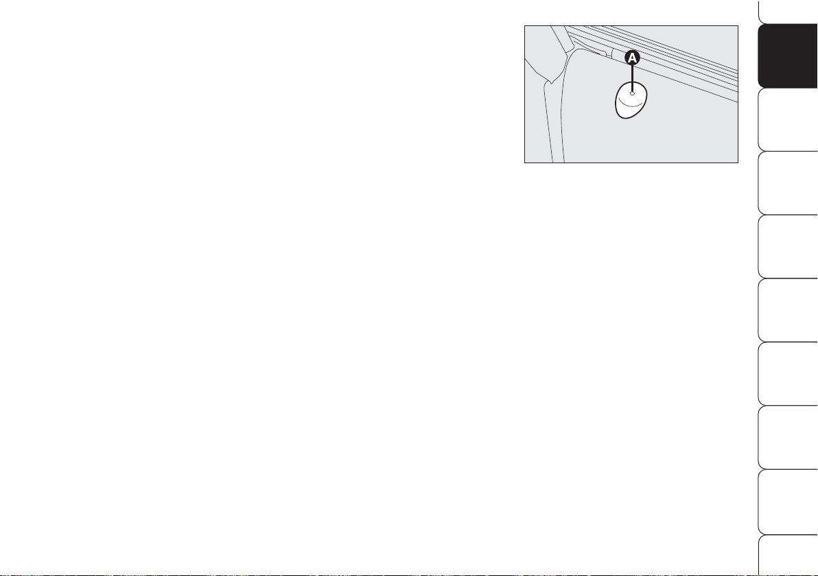
HOW TO ACTIVATE
THE ALARM
With the doors, bonnet and boot shut
and electronic key removed from ignition switch, point the electronic key in
the direction of the car, then press and
release the button
Á
.
With the exception of certain markets,
the system sounds a “beep” and the
doors are locked.
Engagement of the alarm is preceded
by a self-diagnostic test characterised by
a different flashing of the driver’s door
led A-fig. 11: if a fault is detected the
system sounds a further warning
“beep”.
ALARM
(for versions/markets, where provided)
WHEN THE ALARM
IS TRIGGERED
The alarm comes into action in the following cases:
❒
unlawful opening of doors, bonnet
and boot (perimetral protection);
❒
attempt to start the engine with
unauthorised electronic key;
❒
battery cable cutting;
❒
presence of moving bodies in the
passenger’s compartment (volumetric protection);
❒
abnormal raising/sloping of the car
(for versions/markets, where provided);
Volumetric and anti-raising protections
can be cut off by operating the front ceiling light controls(see paragraph “Volumetric protection/Anti-raising sensor”
on the following pages).
A0G0034m
fig. 11
Page 19
HOW TO DEACTIVATE
THE ALARM
Press button Ë. The system will react as
follows (with the exception of certain
markets):
❒
two brief flashes of the direction indicators;
❒
two brief “beeps”;
❒
door unlocking.
The alarm can be deactivated by fitting
the electronic key into the ignition
switch.
IMPORTANT On certain versions any
attempt to break in detected by the system will be indicated by a warning message on the instrument panel display
when fitting the electronic key into the
ignition switch.
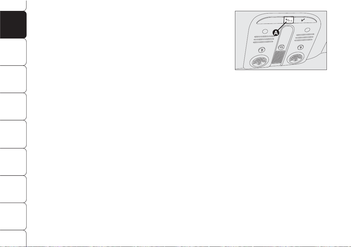
VOLUMETRIC PROTECTION/
ANTI-RAISING SENSORS
To make sure that the protection sensors
are working properly, check that windows are shut.
This function can be cut out (for example if you leave animals on the car) by
pressing button A-fig. 12 on the front
ceiling light within 1 minute after instrument panel turning off.
When this function is off the button led
will turn on. Volumetric protection/antiraising sensors cut out shall be repeated
at each instrument panel turning off.
Surveillance
When the system has been turned on,
the led A-fig. 11 will flash to indicate
that the system is in the surveillance
mode. The led will flash continuously
while the system is under surveillance.
IMPORTANT Operation of the alarm
is adapted at the origin to the regulations of the different countries.
Self-diagnosis and monitoring
of doors/bonnet/boot
If, after the alarm has been activated, a
second acoustic signal is heard, turn the
system off by pressing button
Ë
, check
for proper locking of doors, bonnet and
boot, then turn the system on again by
pressing button
Á
.
Otherwise if a door or bonnet/boot lid
is not correctly closed it will not be controlled by the system. If the control signal is repeated when the doors and bonnet/boot are closed properly this means
that the self-diagnosis function has detected a system operating fault, in which
case it is necessary to contact Alfa
Romeo Authorized Services.
18
SAFETY
DEVICES
WARNING
LIGHTS AND
MESSAGES
IN AN
EMERGENCY
CAR
MAINTENANCE
TECHNICAL
SPECIFICATIONSINDEX
DASHBOARD
AND
CONTROLS
CORRECT USE
OF THE CAR
A0G0086m
fig. 12
Page 20
19
SAFETY
DEVICES
WARNING
LIGHTS AND
MESSAGES
IN AN
EMERGENCY
CAR
MAINTENANCE
TECHNICAL
SPECIFICATIONS
INDEX
DASHBOARD
AND
CONTROLS
CORRECT USE
OF THE CAR
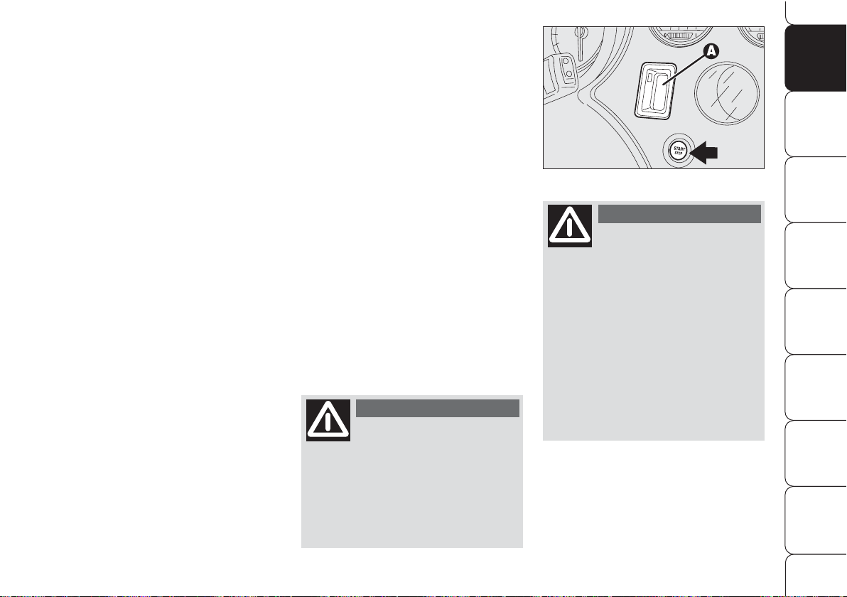
IGNITION DEVICE
The ignition device is located on the
dashboard and it consists of the following:
❒
electronic key reading device
A-fig. 13 (set near the steering
wheel);
❒
button START/STOP (set under
the electronic key reading device).
IMPORTANT To prevent running
down the battery do not leave the electronic key into the ignition device when
the engine is off.
HOW TO CUT OFF
THE ALARM SYSTEM
To deactivate the alarm system completely (for instance during prolonged
inactivity of the car) simply lock the car
by rotating the metal insert (provided
inside the electronic key) into the driver’s door lock.
MINISTERIAL
HOMOLOGATION
In keeping with the laws in force in each
country on the subject of radio frequency, for markets in which the transmitter needs to be marked the certification number is given on the component. For certain versions/markets, the
code may also be marked on the transmitter and/or on the receiver.
A0G0219m
fig. 13
If the ignition device is
tampered with (for example during an attempted
break-in) have it checked over
by Alfa Romeo Authorized
Services before travelling
again.
WARNIN G
When leaving the car
always remove the
electronic key from the ignition
device to prevent any passenger in the car from inadvertently activating the controls.
Remember to engage the
handbrake and if the car is facing uphill, first gear and if the
car is facing downhill, reverse.
Never leave children unattended in the car.
WARNIN G
Page 21
TURNING THE INSTRUMENT
PANEL OFF
With the engine off and brake and clutch
pedal released, press button START/
STOP or take the electronic key out
of the ignition device.
Few seconds after the instrument panel will gradually turn off.
IMPORTANT If when removing the
electronic key from the ignition device
the instrument panel stays on, contact
Alfa Romeo Authorized Services.
TURNING THE INSTRUMENT
PANEL ON
Proceed as follows:
❒
fit the electronic key into the ignition
device;
❒
if the electronic key is fitted yet, press
button START/STOP without
pressing the clutch or brake pedal.
To safeguard the battery, when leaving
the car with the instrument panel on,
electric and electronic devices will be deactivated after approx. 1 hour.
IMPORTANT Fit the electronic key into the ignition device completely until
it locks into place.
IMPORTANT If when fitting the electronic key into the ignition device the instrument panel stays off, contact Alfa
Romeo Authorized Services.
IMPORTANT If when fitting the electronic key into the ignition device, symbol
Y
is displayed (on certain versions
together with a message) check
whether the electronic key is the proper one and then try to refit it into the
ignition device. If the problem persists
contact Alfa Romeo Authorized Services.
20
SAFETY
DEVICES
WARNING
LIGHTS AND
MESSAGES
IN AN
EMERGENCY
CAR
MAINTENANCE
TECHNICAL
SPECIFICATIONSINDEX
DASHBOARD
AND
CONTROLS
CORRECT USE
OF THE CAR
A0G0028m
fig. 14
ENGINE STARTING
See paragraph “Engine starting” in section “Correct use of the car”.
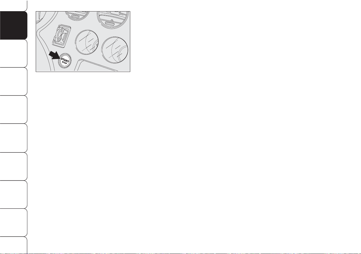
START/STOP BUTTON
fig. 14
Button START/STOP, set on the
dashboard, controls car electric systems
and engine starting/stopping.
Button START/STOP is fitted with
knurled ring and led. When the led and
the instrument panel are on, the engine
can be started.
Page 22
It is absolutely forbidden
to carry out whatever
after-market operation involving steering system or steering
column modifications (e.g.: installation of anti-theft device)
that could badly affect performance and safety, cause the
lapse of warranty and also result in non-compliance of the car
with homologation requirements.
WARNIN G
21
SAFETY
DEVICES
WARNING
LIGHTS AND
MESSAGES
IN AN
EMERGENCY
CAR
MAINTENANCE
TECHNICAL
SPECIFICATIONS
INDEX
DASHBOARD
AND
CONTROLS
CORRECT USE
OF THE CAR
Disengaging
The steering column lock will disengage
after fitting the electronic key into the
ignition device.
IMPORTANT Switching the engine off
when the car is running will not engage
the steering column lock till next switching off of the engine with car stopped. In
this event a dedicated message will be displayed.
IMPORTANT Steering column lock failure is indicated by symbol + message on
the display. In this event contact Alfa
Romeo Authorized Services.
STEERING COLUMN LOCK
Engaging
The steering column lock will engage
5 seconds after removing the electronic key from the ignition device and if the
following conditions are present:
❒
engine off;
❒
instrument panel off with car at a
standstill;
❒
electronic key removed from ignition
device.
IMPORTANT If after turning the instrument panel on and/or starting the engine, the display shows the message “Car
protection system not available”, repeat
the operation using the moving the steering wheel to facilitate steering column unlocking. Displaying of the warning message will not impair steering column lock
regular operation.
Page 23

22
SAFETY
DEVICES
WARNING
LIGHTS AND
MESSAGES
IN AN
EMERGENCY
CAR
MAINTENANCE
TECHNICAL
SPECIFICATIONSINDEX
DASHBOARD
AND
CONTROLS
CORRECT USE
OF THE CAR
FUEL GAUGE fig. 15
The pointer shows the amount of fuel
left in the tank.
0 - tank empty.
1 - tank full (see the indications given
in paragraph “At the filling station").
The fuel gauge warning light turns on to
indicate that approx. 10 litres of fuel are
left in the tank. When range falls below
50 km (or 31 mi) the display will show
a dedicated warning message.
IfKwarning light starts
flashing when travelling, contact Alfa Romeo
Authorized Services.
A0G00177m
fig. 15
INSTRUMENTS
REV. COUNTER
Rev counter shows engine rpm. The danger zone (red) indicates excessive high
engine revs. Do not drive for long periods with the pointer in this area.
IMPORTANT The electronic injection
control system gradually shuts off the
flow of fuel when the engine is “overrevving” (rev counter pointer in the red
area), resulting in a gradual loss of engine power, in order to restore proper
engine rpm.
When the engine is idling, the rev counter
may indicate a gradual or sudden speed
increase. This is normal as it takes place
during normal operation, for example
when activating the climate control system
or the fan. In particular a slow change in
the speed preserves the battery charge.
Page 24
23
SAFETY
DEVICES
WARNING
LIGHTS AND
MESSAGES
IN AN
EMERGENCY
CAR
MAINTENANCE
TECHNICAL
SPECIFICATIONS
INDEX
DASHBOARD
AND
CONTROLS
CORRECT USE
OF THE CAR
IMPORTANT Under certain conditions
(heavy slopes, for instance), the reading
on the gauge may differ from the actual
amount of fuel in the tank and changes
in level may be indicated late. This condition falls within the regular operating logics of the fuel gauge.
The turning on of the
u
warning light
(together with a message on the display) indicates that the coolant fluid
temperature is too high; in this case,
stop the engine and contact Alfa Romeo
Authorized Services.
IMPORTANT The temperature of the
engine coolant may rise towards the
maximum values (red sector) when the
car is driven at low speeds, uphill, fully
laden or during towing, especially if the
ambient temperature is high.
A0G0178m
fig. 16
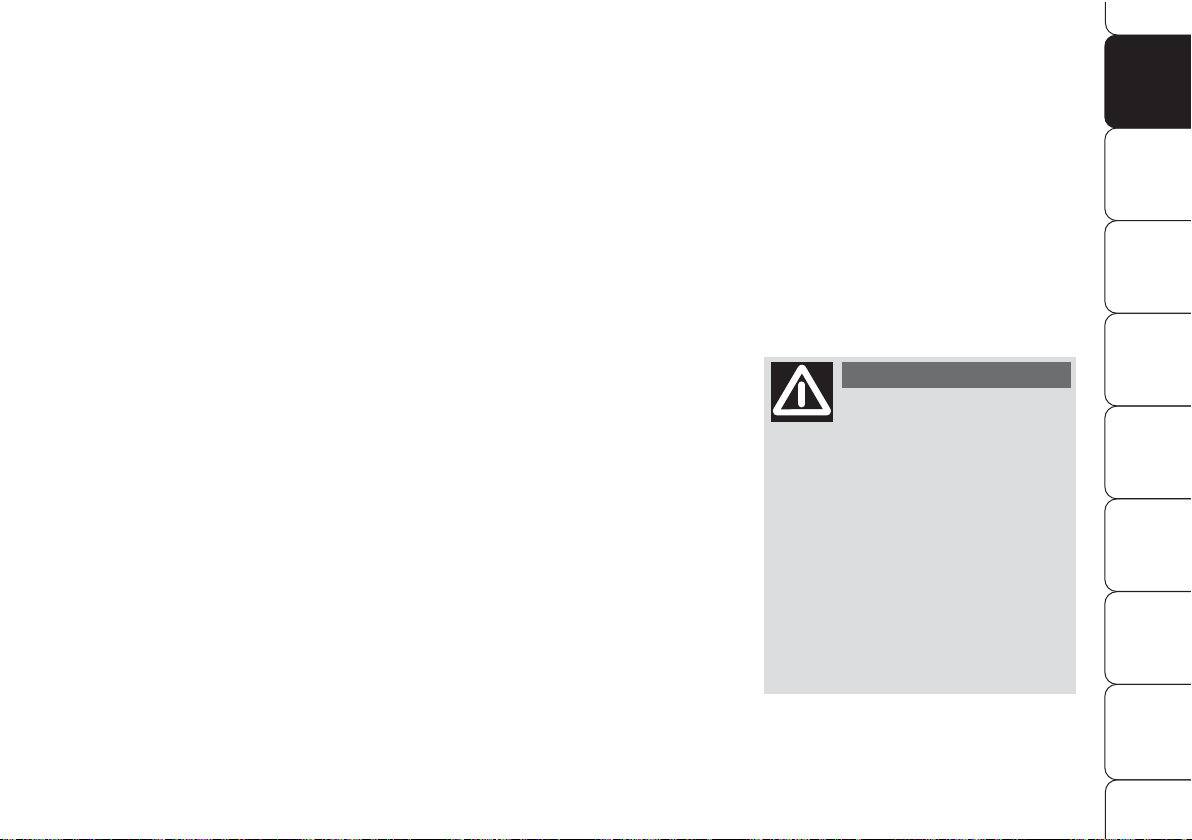
ENGINE COOLANT
TEMPERATURE GAUGE
fig. 16
This shows the temperature of the engine coolant fluid and begins working
when the fluid temperature exceeds approx. 50°C.
The pointer should normally be towards
the middle of the scale. If the pointer
reaches the red sector, reduce your demand on the engine.
Page 25
24
SAFETY
DEVICES
WARNING
LIGHTS AND
MESSAGES
IN AN
EMERGENCY
CAR
MAINTENANCE
TECHNICAL
SPECIFICATIONSINDEX
DASHBOARD
AND
CONTROLS
CORRECT USE
OF THE CAR
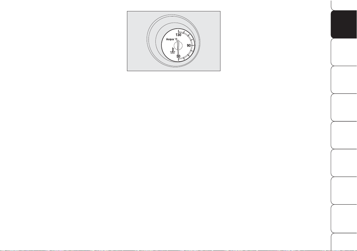
ENGINE OIL TEMPERATURE
GAUGE (petrol version
excluded 1750 TURBO
BENZINA) fig. 17
This shows the temperature of the engine oil and begins working when the
oil temperature exceeds approx. 70°C.
If the pointer reaches the red sector, reduce your demand on the engine.
A0G0179m
fig. 17
The turning on of the
`
warning light
when travelling (together with a message on the display) indicates that the
oil temperature is too high; in this case,
stop the engine and contact Alfa Romeo
Authorized Services.
IMPORTANT The temperature of the
engine oil may rise towards the maximum values (red sector) when the car
is driven at low speeds, uphill, fully
laden or during towing, especially if the
ambient temperature is high.
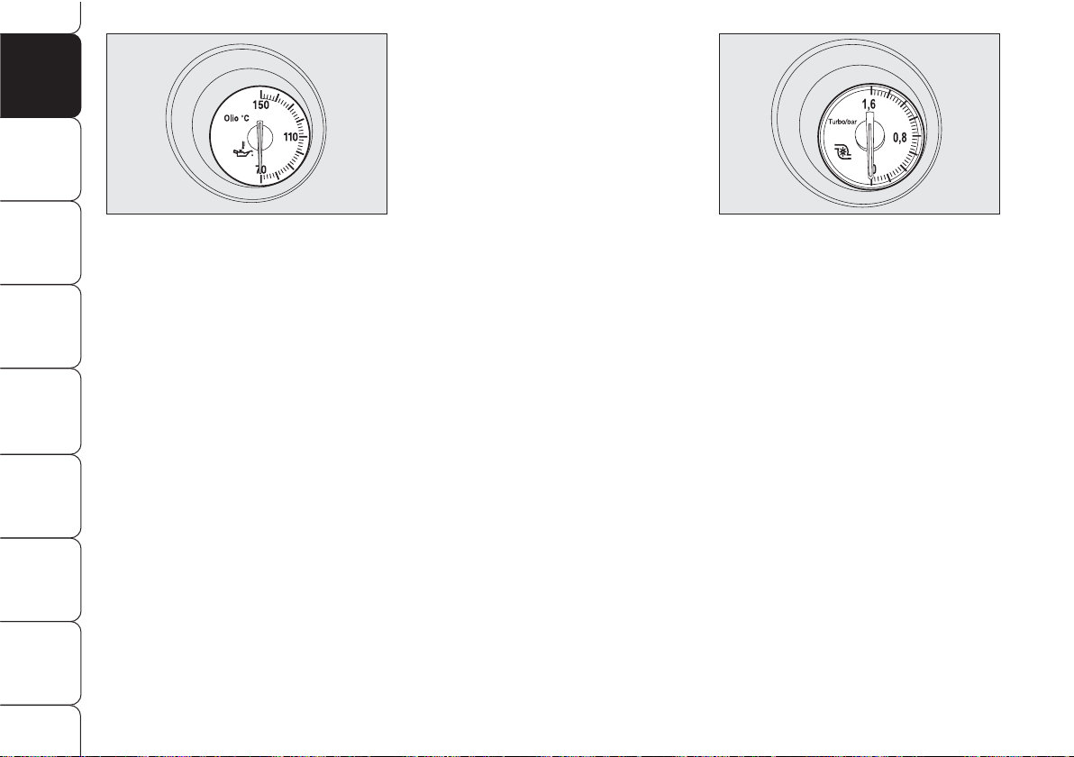
TURBOCHARGER PRESSURE
GAUGE (1750 TURBO
BENZINA and diesel
versions) fig. 18
This shows the turbocharger pressure
value.
A0F0180m
fig. 18
Page 26
25
SAFETY
DEVICES
WARNING
LIGHTS AND
MESSAGES
IN AN
EMERGENCY
CAR
MAINTENANCE
TECHNICAL
SPECIFICATIONS
INDEX
DASHBOARD
AND
CONTROLS
CORRECT USE
OF THE CAR
AUTOMATIC INSTRUMENT
PANEL LIGHT DIMMER
To give max. visibility and comfort under whatever driving conditions (e.g.:
lights on in daylight, tunnels, etc…), the
speedometer is fitted with a sensor for
adjusting automatically, after fitting the
electronic key into the ignition device and
pressing button START/STOP, the
light intensity of the instrument panel display, sound system display, climate control system display, radionavigation system display (for versions/markets,
where provided), and instruments (i.e.:
fuel level gauge, engine oil temperature
gauge for petrol versions or turbocharger pressure gauge for diesel versions, and
engine coolant temperature gauge).
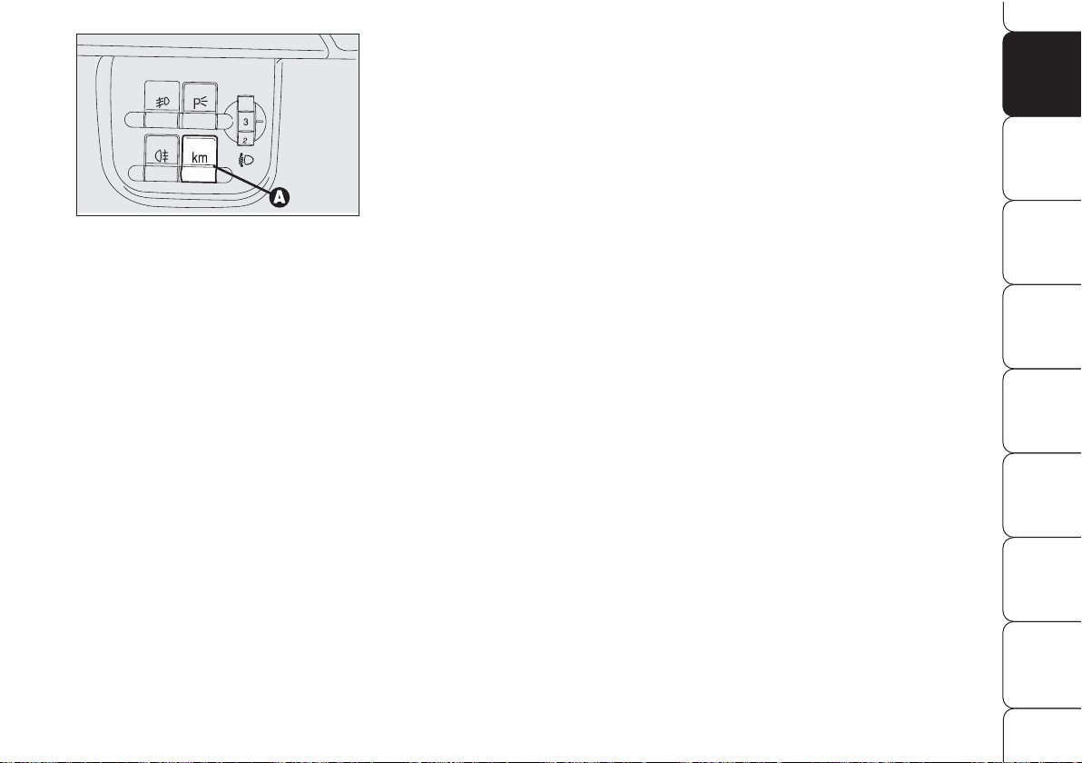
TRIP METER RESET
fig. 18/a
To reset the trip meter, keep button A
pressed for a few seconds.
MANUAL INSTRUMENT
PANEL LIGHT DIMMER
With this function it is possible to adjust
on 8 levels the light intensity of the indications given on the instrument panel display, sound system display, climate control system display, radionavigation system display (for versions/markets,
where provided), and instruments (i.e.:
fuel level gauge, engine oil temperature
gauge for petrol versions or turbocharger
pressure gauge for diesel versions, and engine coolant temperature gauge).
To increase lighting press briefly button
+ on the left stalk and press button –
for dimming: the display will show a
message and the figure indicating the
current lighting level selected. This
screen will stay on for a few seconds
then it turns off.
A0G0072m
fig. 18/a
Page 27
26
SAFETY
DEVICES
WARNING
LIGHTS AND
MESSAGES
IN AN
EMERGENCY
CAR
MAINTENANCE
TECHNICAL
SPECIFICATIONSINDEX
DASHBOARD
AND
CONTROLS
CORRECT USE
OF THE CAR
The date C in the middle of the display
will stay on until another display info is
activated (e.g. “Light dimmer”) or other information on car conditions.
With ignition key removed (when opening a door) the display will turn on and
indicate for a few seconds time, km (or
mi) covered and external temperature .
INFORMATION ABOUT CAR
CONDITIONS (at event)
❒
Scheduled servicing;
❒
Trip computer;
❒
Instrument panel light dimmer;
❒
Engine oil level;
IMPORTANT When opening a door
the display will show for a few seconds
the time, the km covered and the external temperature.
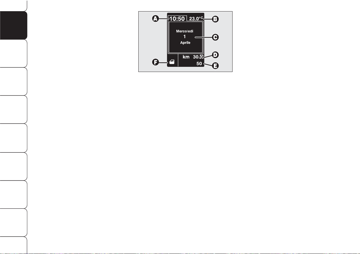
RECONFIGURABLE
MULTIFUNCTION
DISPLAY
The “Reconfigurable multifunction display” shows all the useful information
necessary when driving, more particularly:
INFORMATION ON
STANDARD SCREEN
❒
Clock A-fig. 19;
❒
External temperature B;
❒
Date C;
❒
Partial km (or miles) covered D;
❒
Total km (or miles) covered E;
❒
Indications on car conditions F (e.g.:
doors open, or possible ice on road,
etc. ...).
A0G0015m
fig. 19
Page 28
27
SAFETY
DEVICES
WARNING
LIGHTS AND
MESSAGES
IN AN
EMERGENCY
CAR
MAINTENANCE
TECHNICAL
SPECIFICATIONS
INDEX
DASHBOARD
AND
CONTROLS
CORRECT USE
OF THE CAR
A0G0074m
fig. 20
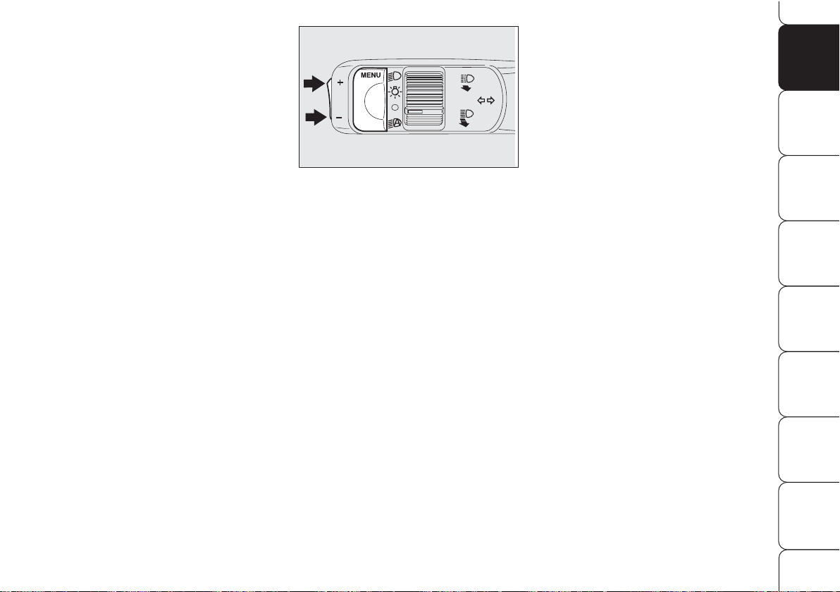
“SETUP MENU”
There is also a “Setup Menu” enabling
to perform the adjustments and/or settings described on the following pages
by pressing button MENU and +/–
(see fig. 20). The Setup menu can be
activated by pressing briefly button
MENU.
The menu comprises a series of functions arranged in a “circular fashion”
fig. 25.
Selecting an option of the main
menu without submenu:
❒
briefly press button MENU to select
the main menu option to set;
❒
operate buttons + or – (by single
press) to select the new setting;
❒
briefly press button MENU to store
new setting and go back to the previously selected option of the main
menu.
CONTROL BUTTONS
MENU
Short push on button: to confirm
the required option and/or to go to next
screen;
Long push on button: to go back to
previous screen without storing setting;
+/– to scroll up/down the “Setup
Menu” options or to increase/decrease
the value displayed on the screen.
When the standard screen is displayed
buttons +/– activate instrument panel
light dimming.
Page 29

28
SAFETY
DEVICES
WARNING
LIGHTS AND
MESSAGES
IN AN
EMERGENCY
CAR
MAINTENANCE
TECHNICAL
SPECIFICATIONSINDEX
DASHBOARD
AND
CONTROLS
CORRECT USE
OF THE CAR
Selecting “Date” and “Clock”:
❒
briefly press button MENU to select
the first value to change (e.g. hours
/minutes or year /month /day);
❒
operate buttons + or – (by single
press) to select the new setting;
❒
briefly press button MENU to store
new setting and go back to the previously selected option of the main
menu, if this is the last one you will
go back to the previously selected
option of the main menu.
ENGINE OIL LEVEL DISPLAY
Fitting the electronic key into the ignition device, the display will show for a
few seconds the engine oil level. At this
stage, to clear this indication and to go
to next screen, press button MENU.
If engine oil level is too low/high, the
display will show the relevant warning
message.
IMPORTANT Check the proper engine oil level on the dipstick (see paragraph “Checking fluid levels” in section
“Car maintenance”).
IMPORTANT Proper engine oil level
shall be checked with the car on level
ground.
IMPORTANT For proper oil level reading, after fitting the key wait for at least
2 seconds before starting the engine.
IMPORTANT Engine oil level may appear increased after prolonged parking.
Selecting an option of the main
menu with submenu:
❒
briefly press button MENU to display the first submenu option;
❒
operate buttons + or – (by single
press) to scroll all submenu options;
❒
briefly press button MENU to select
the displayed submenu option and
to enter the corresponding setup
menu;
❒
operate buttons + or – (by single
press) to select the new setting of this
submenu option;
❒
briefly press button MENU to store
the new setting and go back to the
previously selected submenu option.
Page 30
29
SAFETY
DEVICES
WARNING
LIGHTS AND
MESSAGES
IN AN
EMERGENCY
CAR
MAINTENANCE
TECHNICAL
SPECIFICATIONS
INDEX
DASHBOARD
AND
CONTROLS
CORRECT USE
OF THE CAR
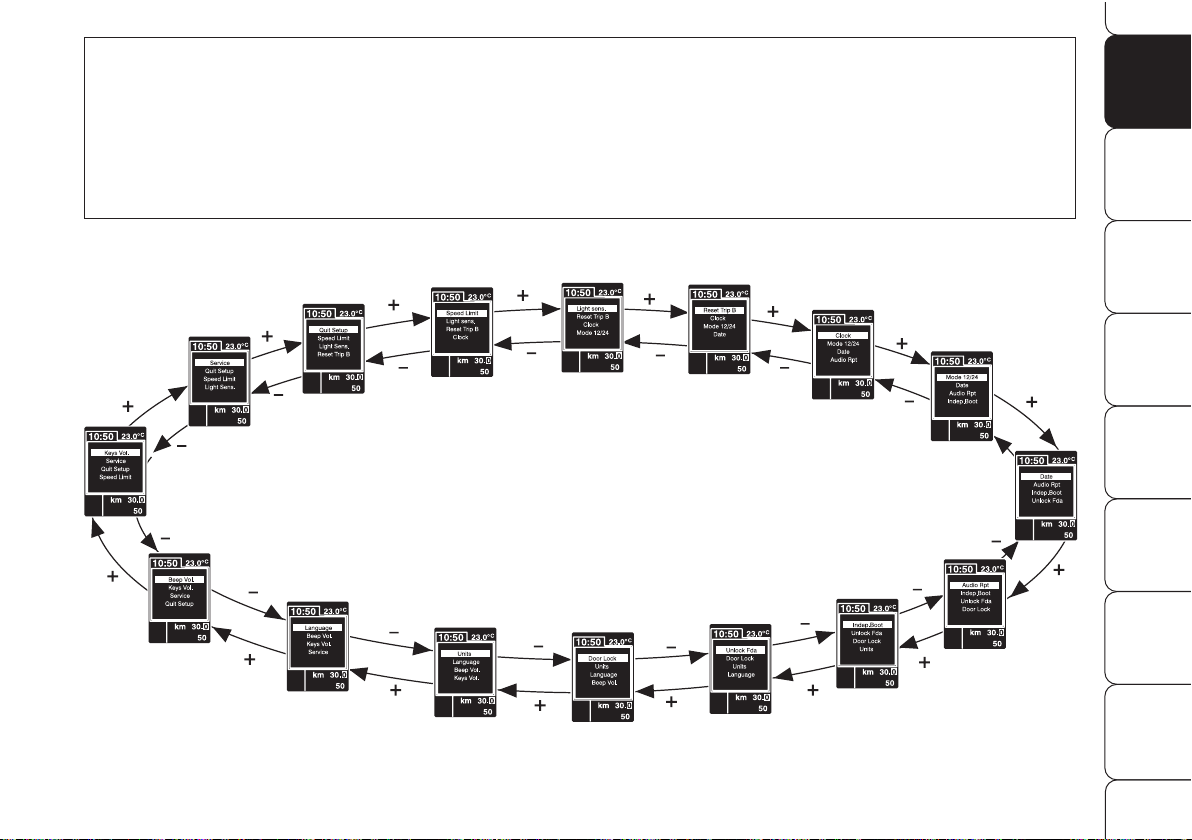
Briefly press button MENU to access navigation from the standard screen. To surf the menu press buttons + or –. For safety reasons, when the car is running, it is possible to access only the reduced menu (for setting “Speed limit”). When the car is stationary
access to the whole menu is enabled. On cars fitted with radionavigation system, only the following functions can be set: “Speed
limit”, “Automatic headlight daylight sensor” (for versions/markets, where provided) e “S.B.R. buzzer reactivation”. The other
functions are displayed and can be set/adjusted on the radionavigation system display.
fig. 21
BEEP VOL.
SERVICE
QUIT SETUP
LIGHT SENS.
RESET TRIP B
CLOCK
MODE 12/24
DATE
AUDIO RPT.
INDEP. BOOT
UNLOCK FDA
DOOR LOCK
UNITS
KEYS VOL.
LANGUAGE
SPEED LIMIT
A0G0218g
Page 31

30
SAFETY
DEVICES
WARNING
LIGHTS AND
MESSAGES
IN AN
EMERGENCY
CAR
MAINTENANCE
TECHNICAL
SPECIFICATIONSINDEX
DASHBOARD
AND
CONTROLS
CORRECT USE
OF THE CAR
Automatic headlight daylight
sensor (Light Sens.)
(for versions/markets, where provided)
With this function it is possible to adjust
the light sensor sensitivity according to
3 levels.
To adjust the volume proceed as follows:
❒
briefly press button MENU: the previously set level will be displayed;
❒
press button + or – for setting as required;
❒
briefly press button MENU to go
back to the menu screen or press the
button for long to go back to the
standard screen.
Reset Trip B (Reset Trip B)
This function enables to select Trip B reset mode (Automatic or Manual).
For further information see paragraph
“Trip computer”.
Speed limit (Speed limit)
With this function it is possible to set the
car speed limit (km/h or mph), which,
if exceeded, automatically sounds a
buzzer and displays a special message
(see section “Warning lights and messages”) to alert the driver.
To set the speed limit, proceed as follows:
❒
briefly press button MENU: OFF
will be displayed;
❒
press button +: ON will be displayed;
❒
briefly press button MENU then,
use buttons +/– to set the required
speed (during setting the value will
flash).
❒
briefly press button MENU to go
back to the menu screen or press the
button for long to go back to the
standard screen.
IMPORTANT The possible setting is
between 30 and 250 km/h (or between 20 and 150 mph) depending on
the unit set previously (see paragraph
“Units” described later). Every press
(pulse) of the button +/– increases or
decreases the value by 5 units. Keeping
the button +/– pressed obtains automatic fast increase or decrease. When
you are near the required setting complete adjustment with single presses.
To abort the setting:
❒
briefly press button MENU: ON
will be displayed;
❒
press button –: OFF will be displayed;
❒
briefly press button MENU to go
back to the menu screen or press the
button for long to go back to the
standard screen.
Page 32

31
SAFETY
DEVICES
WARNING
LIGHTS AND
MESSAGES
IN AN
EMERGENCY
CAR
MAINTENANCE
TECHNICAL
SPECIFICATIONS
INDEX
DASHBOARD
AND
CONTROLS
CORRECT USE
OF THE CAR
IMPORTANT Every press (pulse) on
the button +/–increases/decreases by
one unit. Keeping button +/– pressed
obtains fast increase/decrease. When
you are near the required setting complete adjustment with single presses.
❒
briefly press button MENU to go
back to the menu screen or press the
button for long to go back to the
standard screen.
Setting the clock (Clock)
This function enables to set the clock.
Proceed as follows:
❒
briefly press button MENU: “hours”
will be displayed;
❒
press button + or – for setting as required;
❒
briefly press button MENU: “minutes” will be displayed;
❒
press button + or – for setting as required;
Clock mode (Mode 12/24)
This function is used to set the clock in
the 12h or 24h mode.
To adjust proceed as follows:
❒
briefly press button MENU: the display will show 12h or 24h (according to previous setting);
❒
press button + or – for setting as required;
❒
briefly press button MENU to go
back to the menu screen or press the
button for long to go back to the
standard screen.
Page 33

32
SAFETY
DEVICES
WARNING
LIGHTS AND
MESSAGES
IN AN
EMERGENCY
CAR
MAINTENANCE
TECHNICAL
SPECIFICATIONSINDEX
DASHBOARD
AND
CONTROLS
CORRECT USE
OF THE CAR
Setting the date (Date)
This function enables to update the date
(year - month - day).
Proceed as follows:
❒
briefly press button MENU : “year”
will flash on the display;
❒
press button + or – for setting as required;
❒
briefly press button MENU: “month”
will flash on the display;
❒
press button + or – for setting as required;
❒
briefly press button MENU : “day”
will flash on the display;
❒
press button + or – for setting as required;
IMPORTANT Every press (pulse) on
the button +/–increases/decreases by
one unit. Keeping button +/– pressed
obtains fast increase/decrease. When
you are near the required setting complete adjustment with single presses.
❒
briefly press button MENU to go
back to the menu screen or press the
button for long to go back to the
standard screen.
Audio Info Repetition
(Audio Rpt.) (where provided)
This function enables to display sound
system information.
❒
Radio: selected radio station frequency or RDS message, automatic
tuning activation or AutoSTore;
❒
audio CD, MP3 CD: selected track
number;
❒
CD Changer: CD number and track
number;
To activate/deactivate (ON/OFF) info displaying proceed as follows:
❒
briefly press button MENU: the display will show ON or OFF (according to previous setting);
❒
press button + or – for setting as required;
❒
briefly press button MENU to go
back to the menu screen or press the
button for long to go back to the
standard screen.
According to the audio source selected,
below the time will be displayed the
symbol of the current source.
Page 34

33
SAFETY
DEVICES
WARNING
LIGHTS AND
MESSAGES
IN AN
EMERGENCY
CAR
MAINTENANCE
TECHNICAL
SPECIFICATIONS
INDEX
DASHBOARD
AND
CONTROLS
CORRECT USE
OF THE CAR
Driver’s door unlocking
(Unlock Fda)
With this function it is possible to unlock
only the driver’s door by pressing the
electronic key button
Ë
.
With this function active (ON) it is however possible to unlock the other doors
by pressing the door unlock button on
central console.
To activate/deactivate (ON/OFF) this
function proceed as follows:
❒
briefly press button MENU: the display will show ON or OFF (according to previous setting);
❒
press button + or – for setting as required;
❒
briefly press button MENU to go
back to the menu screen or press the
button for long to go back to the
standard screen.
Automatic central door locking
(Door lock)
When activated (ON), this function
locks automatically the doors when the
car speed exceeds 20 km/h.
To activate/deactivate (ON/OFF) this
function proceed as follows:
❒
briefly press button MENU: the display will show ON or OFF (ac-
cording to previous setting);
❒
press button + or – for setting as required;
❒
briefly press button MENU to go
back to the menu screen or press the
button for long to go back to the
standard screen.
When the function is on, the button
round led is on
q
.
Independent boot unlocking
(Indep. Boot)
The boot can always be opened with the
remote control (press button
`
). “Indep. Boot” option enables or disables the
button set on the armrest, more particularly: with “Indep. Boot ON” the button
is always disabled. With “Indep. Boot
OFF” the button is enabled and pressing
the button will unlock the boot if door
locks are unlocked.
To activate this function (disabling the
armrest button) (ON) or to deactivate
it (OFF, boot interlocking with doors),
proceed as follows:
❒
briefly press button MENU: the display will show ON or OFF (ac-
cording to previous setting);
❒
press button + or – for setting as required;
❒
briefly press button MENU to go
back to the menu screen or press the
button for long to go back to the
standard screen.
Page 35

Consumption
If the distance unit set is km (see previous paragraph) the display will enable
to set the fuel consumption unit in
l/100 km, km/l or mpg.
If the distance unit set is “mi” (see previous paragraph) fuel consumption will
be displayed in “mpg”.
In this case the option “Cons.Unit” of the
“Setup Menu” can be selected but it is
locked on “mpg”.
To set the required unit proceed as follows:
❒
briefly press button MENU: the display will show “km/l” or “l/100
km” (according to previous setting);
❒
press button + or – for setting as required;
❒
briefly press button MENU to go
back to the menu screen or press the
button for long to go back to the
standard screen.
Temperature
This function enables to set the temperature unit (°C or °F).
To set the required unit proceed as follows:
❒
briefly press button MENU: the display will show °C or °F (according
to previous setting);
❒
press button + or – for setting as required;
❒
briefly press button MENU to go
back to the menu screen or press the
button for long to go back to the
standard screen.
Units
With this function it is possible to set the
units for distance covered (km or mi),
fuel consumption (l/100 km, km/l or
mpg) and temperature (°C or °F).
Distance
To set the required unit proceed as follows:
❒
briefly press button MENU: the display will show “km” or “mi” (according to previous setting);
❒
press button + or – for setting as required;
❒
briefly press button MENU to go
back to the menu screen or press the
button for long to go back to the
standard screen.
34
SAFETY
DEVICES
WARNING
LIGHTS AND
MESSAGES
IN AN
EMERGENCY
CAR
MAINTENANCE
TECHNICAL
SPECIFICATIONSINDEX
DASHBOARD
AND
CONTROLS
CORRECT USE
OF THE CAR
Page 36

35
SAFETY
DEVICES
WARNING
LIGHTS AND
MESSAGES
IN AN
EMERGENCY
CAR
MAINTENANCE
TECHNICAL
SPECIFICATIONS
INDEX
DASHBOARD
AND
CONTROLS
CORRECT USE
OF THE CAR
Selecting the language
(Language)
Display messages can be shown in the
following languages: Italian, English,
German, Portuguese, Spanish, French,
Dutch and Brazilian.
To set the required language proceed as
follows:
❒
briefly press button MENU : the display will show the previously set
“language”;
❒
press button + or – for setting as required;
❒
briefly press button MENU to go
back to the menu screen or press the
button for long to go back to the
standard screen.
Adjusting the button volume
(Keys Vol.)
With this function the volume of the
roger-beep accompanying the activation
of certain buttons can be adjusted according to 8 levels.
To adjust the volume proceed as follows:
❒
briefly press button MENU: the display will show the previously set volume “level”;
❒
press button + or – for setting as required;
❒
briefly press button MENU to go
back to the menu screen or press the
button for long to go back to the
standard screen.
Adjusting the failure/warning
buzzer volume (Beep Vol.)
With this function the volume of the
buzzer accompanying any failure/warning indication can be adjusted
according to 8 levels.
To adjust the volume proceed as follows:
❒
briefly press button MENU: the display will show the previously set volume “level”;
❒
press button + or – for setting as required;
❒
briefly press button MENU to go
back to the menu screen or press the
button for long to go back to the
standard screen.
Page 37

Reactivating the S.B.R.
(Seat Belt Reminder) buzzer
(Beep Seatb.)
This function is displayed only after the
system has been deactivated by Alfa
Romeo Authorized Services.
Exit Menu (Quit setup)
Selecting this option will bring back to
standard screen.
ILLUMINATION OF REV
COUNTER/INSTRUMENTS
(NIGHT PANEL)
This function enables to turn on/off
(ON/OFF) the illumination of rev
counter and instruments. This function can
be activated (only with electronic key fitted into ignition device, external lights on,
and speedometer built-in sensor in poor
outside light condition), by pressing for
long button –. When this function is on,
the display will show a warning message.
Once on, the NIGHT PANEL function
can be deactivated as follows:
❒
by long press on button + (also with
external lights off);
❒
removing the electronic key from the
ignition device.
When function is off the display will show
a warning message.
Messages stay on the display for a few
seconds, then they will go off. To stop
displaying before time, briefly press button MENU.
Scheduled Servicing (Service)
Through this function it is possible to display information connected to proper car
servicing.
Proceed as follows:
❒
briefly press button MENU: service
in km or mi, according to previous
setting, will be displayed (see paragraph “Units”);
❒
briefly press button MENU to go
back to the menu screen or press the
button for long to go back to the
standard screen.
IMPORTANT The Service schedule includes car maintenance every 35,000
km (or 21,000 mi); this is shown automatically, with the electronic key into the
ignition device starting from 2,000 km
(or 1,240 mi) from this deadline and it
will be displayed in km or miles according to the unit set. When a scheduled service interval (“coupon”) is near to come,
fitting the electronic key into the ignition
device will display a message followed
by the number of km/mi to go before
car servicing. Contact Alfa Romeo Authorized Services to carry out any service
operation provided by the Service schedule or by the Annual inspection plan, and
to reset the display.
36
SAFETY
DEVICES
WARNING
LIGHTS AND
MESSAGES
IN AN
EMERGENCY
CAR
MAINTENANCE
TECHNICAL
SPECIFICATIONSINDEX
DASHBOARD
AND
CONTROLS
CORRECT USE
OF THE CAR
Page 38

37
SAFETY
DEVICES
WARNING
LIGHTS AND
MESSAGES
IN AN
EMERGENCY
CAR
MAINTENANCE
TECHNICAL
SPECIFICATIONS
INDEX
DASHBOARD
AND
CONTROLS
CORRECT USE
OF THE CAR
Reset TRIP B
End of partial mission
Start of new partial mission
End of partial mission
Start of new
partial mission
Reset TRIP B
End of partial mission
Start of new
partial mission
Reset GENERAL TRIP
End of complete mission
Start of new mission
Reset GENERAL TRIP
End of complete mission
Start of new mission
End of partial mission
Start of new
partial mission
Reset TRIP B
Reset TRIP B
TRIP B
TRIP B
TRIP B
GENERAL TRIP
˙
˙
˙
˙
˙
˙
˙
˙
fig. 22
TRIP COMPUTER
General features
The “Trip computer” displays information (with electronic key fitted into ignition device) relating to the operating status of
the car. This function comprises the “General trip” concerning the “complete mission” of the car (journey) and “Trip B” concerning the partial mission of the car; this latter function (as shown in fig. 22) is “contained” within the complete mission.
Both functions are resettable (reset - start of new mission).
Page 39

38
SAFETY
DEVICES
WARNING
LIGHTS AND
MESSAGES
IN AN
EMERGENCY
CAR
MAINTENANCE
TECHNICAL
SPECIFICATIONSINDEX
DASHBOARD
AND
CONTROLS
CORRECT USE
OF THE CAR
Values displayed
Average consumption
Represents the indicative average of consumptions from the beginning of the
new mission.
Current consumption
This value shows instant fuel consumption (this value is updated second by
second). If parking the car with engine
on, the display will show “- - - -”.
Average speed
This value shows the car average speed
as a function of the overall time elapsed
since the start of the new mission.
Travel time
This value shows the time elapsed since
the start of the new mission (driving
time).
Range
This value shows the distance in km (or
mi) that the car can still cover before
needing fuel, assuming that driving conditions are kept unvaried.
The display will show “- - - -“ in the following cases:
❒
value lower than 50 km (or 30 mi);
❒
car left parked with engine running
for long.
IMPORTANT The variation of the autonomy value can be influenced by different factors: driving style (see what is
described in paragraph “Driving style”
in the chapter “Correct use of the car”),
type of route (highways, urban, mountain, etc…), use conditions of the car
(load transported, tire pressure, etc…).
What was described previously must be
taken in consideration when planning
a trip.
Travel Distance
This value shows the distance covered
from the start of the new mission.
Each time the battery is connected and
each time a new mission is started (reset), the display will show “0.0”.
The “General Trip” displays the figures
relating to:
❒
Average consumption
❒
Current consumption
❒
Average speed
❒
Travel time
❒
Range
❒
Travel Distance
“Trip B” displays information concerning :
❒
Travel Distance B
❒
Average consumption B
❒
Average speed B
❒
Travel time B.
Page 40

39
SAFETY
DEVICES
WARNING
LIGHTS AND
MESSAGES
IN AN
EMERGENCY
CAR
MAINTENANCE
TECHNICAL
SPECIFICATIONS
INDEX
DASHBOARD
AND
CONTROLS
CORRECT USE
OF THE CAR
TRIP BUTTON
Button TRIP fig. 23, set on the right
steering column stalk shall be used (with
electronic key into ignition device) to enter the “General Trip” and “Trip B” function. To scroll the values of each option
use buttons set aside the stalk.
Button TRIPshall also be used to reset
the “General Trip” and “Trip B” functions
to start a new mission:
❒
short push: to display the different
values;
❒
long push: to reset and then start a
new mission.
To scroll the Trip Computer options,
briefly press buttons
-
and
.
.
New mission (reset)
Reset can be:
❒
“manual”, reset is performed by the
driver by pressing button TRIP;
❒
“automatic”, reset is performed
when the trip distance reaches
9999.9 km (or mi), when travel
time reaches 99.59 (99 hours and
59 minutes) or after disconnecting
and then reconnecting the battery.
A0G0099m
fig. 23
Page 41

40
SAFETY
DEVICES
WARNING
LIGHTS AND
MESSAGES
IN AN
EMERGENCY
CAR
MAINTENANCE
TECHNICAL
SPECIFICATIONSINDEX
DASHBOARD
AND
CONTROLS
CORRECT USE
OF THE CAR
IMPORTANT “General Trip” reset will
also reset the “Trip B” function, whereas “Trip B” reset will only reset the information associated with this function.
Every Trip computer screen displays two
options of the active Trip (Trip A or Trip
B); one option is displayed at the top of
the screen, the other one at the bottom
(see fig. 24).
In the same screen it is not possible to
have displayed at the same time the
same option at the top and at the bottom of the screen.
Briefly press button TRIP to select the
two Trip computer modes; use button
-
to scroll the options at the top of the
display, use button
.
to scroll the op-
tions at the bottom of the display.
Press briefly button TRIP to go from
Trip A to Trip B.
Start of journey procedure
(reset)
Trip A and Trip B reset are independent.
Reset General Trip
With electronic key into ignition device,
to reset the “General Trip” press and
keep pressed button TRIP for over 2
seconds.
IMPORTANT Reset can be automatic only in the following cases:
❒
when the “Travel Distance” reaches 9999.9 km or the “Travel Time”
reaches 99.59 (99 hours and 59
minutes);
❒
after disconnecting/reconnecting the
battery.
At General Trip reset a warning message
will be displayed.
A0G0052m
fig. 24
Page 42

Fabric upholstery of your
car is purpose-made to
withstand common wear
resulting from normal use of the
car. It is however absolutely necessary to prevent hard and/or
prolonged scratching/scraping
caused by clothing accessories
like metallic buckles, studs, “Velcro” fixings, etc. that stressing
locally the fabric could break
yarns and damage the upholstery as a consequence.
41
SAFETY
DEVICES
WARNING
LIGHTS AND
MESSAGES
IN AN
EMERGENCY
CAR
MAINTENANCE
TECHNICAL
SPECIFICATIONS
INDEX
DASHBOARD
AND
CONTROLS
CORRECT USE
OF THE CAR
Height adjustment
(for versions/markets, where provided)
Move repeatedly lever B upwards or
downwards to achieve the required
height.
IMPORTANT Adjustment must be carried out only seated at the driver’s seat.
Back rest angle adjustment
Press button C until obtaining the required position.
SEATS
MANUALLY ADJUSTABLE
SEATS fig. 25
Only make adjustments
when the car is sta-
tionary.
WARNIN G
A0G0020m
fig. 25
Once you have re-
leased the lever, check
that the seat is firmly locked
in the runners by trying to
move it back and forth. Failure
to lock the seat in place could
result in the seat moving suddenly and the driver losing
control of the car.
WARNIN G
Moving the seat backwards
or forwards
Lift the lever A (on the inner side of the
seat) and push the seat forwards or
backwards: in the driving position the
arms should rest on the rim of the steering wheel.
Page 43

Lumbar adjustment
(for versions/markets, where provided)
Turn the knob D until obtaining the re-
quired position.
Back rest angle adjustment
(for versions/markets, where provided)
Use lever E. Pulling the lever upwards
the seat will bend back by one position.
Pushing the lever downwards the seat
will bend forward.
Tilting the back rest
Pull handle F: the back rest will tilt and
the seat can slide forward.
Bringing back the back rest the seat will
return automatically to its original position (mechanical memory).
After bringing the back rest to its original position check tat it firmly locked.
Check also that the seat is firmly locked
in the runners by trying to move it back
and forth.
42
SAFETY
DEVICES
WARNING
LIGHTS AND
MESSAGES
IN AN
EMERGENCY
CAR
MAINTENANCE
TECHNICAL
SPECIFICATIONSINDEX
DASHBOARD
AND
CONTROLS
CORRECT USE
OF THE CAR
ELECTRICALLY ADJUSTABLE
SEATS fig. 26
(for versions/markets, where provided)
Seat controls are the following:
Multifunction control A:
❒
front seat height adjustment;
❒
rear seat height adjustment;
❒
vertical seat movement;
❒
longitudinal seat movement;
B: Back rest angle adjustment;
C: Driver’s seat positions store buttons;
D: Lumbar adjustment;
E: Back rest tipping.
IMPORTANT Seat can only be ad-
justed when the electronic key is fitted
into the ignition device and for about 1
minute from removing it or after pressing button START/STOP. After open-
ing the door the seat can be adjusted for
about 3 minutes or until closing the
door.
Only make adjustments
when the car is sta-
tionary.
WARNIN G
A0G0310m
fig. 26
Page 44

43
SAFETY
DEVICES
WARNING
LIGHTS AND
MESSAGES
IN AN
EMERGENCY
CAR
MAINTENANCE
TECHNICAL
SPECIFICATIONS
INDEX
DASHBOARD
AND
CONTROLS
CORRECT USE
OF THE CAR
Seat warming
(for versions/markets, where provided)
With electronic key fitted into ignition
device, turn ring nut A-fig. 27 to turn
this function on/off.
Seat warming can be adjusted to 3 different levels (0 = seat warming off).
A0G0024m
fig. 27
Storing driver’s seat/
door mirror positions
Buttons Callows to store and recall three
different driver’s seat and door mirror positions. Storing and recalling are only possible with electronic key fitted into ignition device.
Stored position can only be recalled for
about 3 minutes after opening the doors
and for about 1 minute after removing
the electronic key from the ignition device.
To store the required seat position, adjust it as required then press the button
corresponding to position to store for a
few seconds.
To recall the stored position, press briefly
the corresponding button.
Storing a new position will automatically
clear the one stored previously using the
same button.
FRONT SEATS SPORTS
fig. 27/a
(for versions/markets, where provided)
Certain versions are fitted with electri-
cally adjustable front seats with sports
configuration.
To adjust these seats see the indications
contained in previous paragraphs.
A0G0199m
fig. 27/a
Page 45

44
SAFETY
DEVICES
WARNING
LIGHTS AND
MESSAGES
IN AN
EMERGENCY
CAR
MAINTENANCE
TECHNICAL
SPECIFICATIONSINDEX
DASHBOARD
AND
CONTROLS
CORRECT USE
OF THE CAR
STEERING WHEEL
The steering wheel can be adjusted both
axially and in height.
Release the lever A-fig. 28 pushing it
downwards, then adjust the steering
wheel as required. To lock the steering
wheel, push lever A upwards.
It is absolutely forbid-
den to carry out whatever after-market operation
involving steering system or
steering column modifications
(e.g.: installation of anti-theft
device) that could badly affect
performance and safety, cause
the lapse of warranty and also result in non-compliance of
the car with homologation requirements.
WARNIN G
A0G0136m
fig. 28
Any adjustment of the
steering wheel position
must be carried out only with
the car stationary and the engine turned off.
WARNIN G
HEAD RESTRAINTS
Head restraints are built into the seats.
Page 46

45
SAFETY
DEVICES
WARNING
LIGHTS AND
MESSAGES
IN AN
EMERGENCY
CAR
MAINTENANCE
TECHNICAL
SPECIFICATIONS
INDEX
DASHBOARD
AND
CONTROLS
CORRECT USE
OF THE CAR
Adjusting the mirror
Use device A-fig. 30 to select the required mirror:
❒
turn selector A to 1: to select the
left mirror;
❒
turn selector A to 2: to select the
right mirror.
To adjust the mirror move the switch B
in the four directions shown by the arrows.
IMPORTANT After adjusting the mirror, turn selector A to 0 to prevent accidental movements.
DOOR MIRRORS
Door mirror can only be adjusted and
folded when the electronic key is fitted
into the ignition device.
A0G0135m
fig. 29
REARVIEW
MIRRORS
DRIVING MIRROR
The mirror is fitted with a safety device
that causes it to be released in the event
of a violent crash.
Using lever A-fig. 29 the mirror can
be adjusted to two different positions:
normal or antiglare.
A0G0036m
fig. 30
Page 47

46
SAFETY
DEVICES
WARNING
LIGHTS AND
MESSAGES
IN AN
EMERGENCY
CAR
MAINTENANCE
TECHNICAL
SPECIFICATIONSINDEX
DASHBOARD
AND
CONTROLS
CORRECT USE
OF THE CAR
Manual mirror folding
When required (for example when the
mirror causes difficulty in narrow spaces)
it is possible to fold the mirror moving it
from position A-fig. 31 to position B.
Powered mirror folding
(for versions/markets, where provided)
When required (for example when the
mirror causes difficulty in narrow spaces)
it is possible to fold the mirrors by pressing button C-fig. 30.
To bring the mirrors back to driving position press again button C-fig. 30.
A0G0081m
fig. 31
As the driver’s door mirror is curved, it may
slightly alter the per-
ception of distance.
When driving the mir-
rors shall always be in
open position.
WARNIN G
Locking the doors will obtain door mirrors folding; refitting the key will reposition door mirrors automatically.
This function can be activated/deactivated by pressing the mirror
folding button for over 2 seconds.
Buzzer sound will then confirm setting.
Storing the “parking”
position of the door mirror
on the passenger side
On versions equipped with powered
seats, to improve visibility during parking manoeuvres when engaging the reverse gear, the driver can adjust/move
(and store) the passenger door mirror
to a position different from that used
during normal running. To store the required mirror position proceed as follows:
❒
engage reverse with car stopped and
ignition key fitted into ignition device;
❒
turn selector A-fig. 30 to 2 (to select the passenger door mirror);
❒
adjust the passenger door mirror as
required to obtain best position for
parking manoeuvres;
❒
keep one of the buttons C-fig. 28
pressed for 26 seconds at least (see
paragraph “Seats” in this section).
Page 48

47
SAFETY
DEVICES
WARNING
LIGHTS AND
MESSAGES
IN AN
EMERGENCY
CAR
MAINTENANCE
TECHNICAL
SPECIFICATIONS
INDEX
DASHBOARD
AND
CONTROLS
CORRECT USE
OF THE CAR
Together with the passenger door mirror “parking” position, also the driver
seat and door mirror positions will be
stored. The sound of a buzzer confirms
that the mirror position has been stored.
Recalling the passenger
door mirror “parking”
Proceed as follows: fit the electronic key
into the ignition device; engage reverse;
turn selector A-fig. 30 to 2 (to select
the passenger door mirror).
The mirror will set automatically to the
previously stored position.
If no parking position has been stored,
when engaging reverse the passenger
door mirror will slightly lower to aid the
driver during parking.
The mirror will automatically return to
its original position 10 seconds after disengaging reverse, when the car speed
exceeds 10 km/h in forward gear or
when turning selector A-fig. 30 to 0.
Automatic door mirror
realignment
Each time the ignition key is fitted into
the ignition device, door mirrors return
automatically to the last position
reached and/or recalled at last key removal.
This enables mirror alignment if when
leaving the car parked one of the door
mirrors has been moved manually
and/or accidentally.
Defrosting/demisting
The electric mirrors are fitted with heating
coils which come into operation when turning on the heated rear window (by pressing button
(
).
IMPORTANT This function is timed
and is deactivated after a few minutes.
Page 49

48
SAFETY
DEVICES
WARNING
LIGHTS AND
MESSAGES
IN AN
EMERGENCY
CAR
MAINTENANCE
TECHNICAL
SPECIFICATIONSINDEX
DASHBOARD
AND
CONTROLS
CORRECT USE
OF THE CAR
CLIMATE CONTROL SYSTEM
1 Upper vent - 2 Adjustable and swivel central vents - 3 Adjustable and swivel side vents - 4 Lower vents (at feet height) -
5 Windscreen and windows demisting/defrosting vents.
A0G0278m
fig. 32
Page 50

49
SAFETY
DEVICES
WARNING
LIGHTS AND
MESSAGES
IN AN
EMERGENCY
CAR
MAINTENANCE
TECHNICAL
SPECIFICATIONS
INDEX
DASHBOARD
AND
CONTROLS
CORRECT USE
OF THE CAR
CENTRAL AND
SIDE VENTS fig. 33-34
These vents are located on the dashboard. Each vent A features a wheel B
to adjust air flow and a device C to direct it horizontally or vertically.
O = Completely closed
I = Completely open
A0G0014m
fig. 33
A0G0057m
fig. 35
UPPER VENT fig. 35
The vent has an opening/closing control.
O = Completely closed
I = Completely open
WINDSCREEN AND SIDE
WINDOW DEMISTING/
DEFROSTING VENTS
These vents are located at the ends Afig. 36 and on the front part B of the
dashboard.
A0G0012m
fig. 34
A0G0067m
fig. 36
Page 51

50
SAFETY
DEVICES
WARNING
LIGHTS AND
MESSAGES
IN AN
EMERGENCY
CAR
MAINTENANCE
TECHNICAL
SPECIFICATIONSINDEX
DASHBOARD
AND
CONTROLS
CORRECT USE
OF THE CAR
AIR DISTRIBUTION
SELECTION
O
: air flow to driver’s/passenger’s
body;
M
: air flow to driver’s/passenger’s
body and lower part of the passenger
compartment;
N
: air flow towards the lower part of
the passenger compartment;
Q
: air flow towards the lower part of
the passenger compartment and windscreen;
ü
: air flow towards the windscreen
MANUAL CLIMATE
CONTROL SYSTEM
(for versions/markets, where provided)
CONTROLS fig. 37
A - Air temperature knob (mixing warm
and cold air);
B - Air distribution knob;
C - Fan speed knob;
D - Heated rear window and door mir-
ror defrosting on/off button;
E - Windscreen, side windows and door
mirror max. demisting/defrosting
on/off button;
F - Air recirculation on/off button;
G - Compressor on/off button.
fig. 37
A0G0011m
Page 52

51
SAFETY
DEVICES
WARNING
LIGHTS AND
MESSAGES
IN AN
EMERGENCY
CAR
MAINTENANCE
TECHNICAL
SPECIFICATIONS
INDEX
DASHBOARD
AND
CONTROLS
CORRECT USE
OF THE CAR
QUICK WINDSCREEN
AND FRONT SIDE WINDOW
DEMISTING/DEFROSTING
(MAX-DEF function)
To turn this function on press button
-
:
the button leds
-
,√and
(
will turn
on. To turn this function off press again
button
-
the button led will turn off.
After demisting/defrosting, turn this
function off to keep perfect comfort conditions.
Window demisting
Climate control system
√
is very useful to speed up window demisting and
it is therefore to be turned on in the
event of considerable moisture. In any
case it is recommended to perform the
following preventive demisting procedure:
❒
turn air recirculation off (if on);
❒
turn knob C to second speed;
❒
turn knob B toQ.
HEATED REAR WINDOW
AND DOOR MIRROR
DEMISTING/DEFROSTING
To turn this function on press button
(
the button led will turn on. To turn this
function off press again button .
On certain versions, turning this function
on will also activate windscreen defrosting in the windscreen wiper area.
This function is timed and switches off
automatically after few minutes, or by
pressing again the button or by turning
the engine off. It will not be switched
on automatically when restarting the engine.
IMPORTANT Do not apply stickers on
the inside of the heated rear window
over the heating filaments to avoid damage that might cause it to stop working properly.
WARMING THE PASSENGER
COMPARTMENT
Proceed as follows:
❒
turn knob A to the required temperature;
❒
turn knob C to the required speed;
❒
turn knob B to the required distribution:
N
: to warm the feet;
M
: to warm the feet and keep the face
cool (bilevel function);
Q
: to warm the feet and at the same
time demist the windscreen;
❒
turn air recirculation off (if on).
Page 53

52
SAFETY
DEVICES
WARNING
LIGHTS AND
MESSAGES
IN AN
EMERGENCY
CAR
MAINTENANCE
TECHNICAL
SPECIFICATIONSINDEX
DASHBOARD
AND
CONTROLS
CORRECT USE
OF THE CAR
CLIMATE CONTROL
(fast cooling)
IMPORTANT The compressor
√
can
be enabled only if the ventilation is enabled.
Proceed as follows:
❒
turn knob A completely leftwards;
❒
turn knob C to top speed;
❒
turn knob B toO;
❒
press buttons
√
and
v
(buttons
leds on).
How to keep the required
cooling
Proceed as follows:
❒
turn air recirculation off (if on).
❒
turn knob A to the required temperature;
❒
turn the knurled ring C to the required fan speed.
LOOKING AFTER
THE SYSTEM
During the winter, the climate control
system
√
must be turned on at least
once a month for about ten minutes.
Before summer, have the system
checked at Alfa Romeo Authorized Services.
RECIRCULATION
To turn this function on press button
v
: the button led will turn on.
This function is particularly useful when
the outside air is heavily polluted (in a
traffic jam, tunnel, etc.) However, it is
better not to use it for long periods, especially if there are several people in the
car to prevent window misting up.
Do not use the air recirculation function
on rainy/cold days as it would considerably increase the possibility of the windows misting inside.
IMPORTANT The inside air recirculation system makes it possible to reach
the required (“heating” or “cooling”)
conditions faster.
After connecting/disconnecting the battery,
wait for 3 minutes at
least before fitting the electronic key into the ignition device in order to allow the climate control system control unit
to reset the position of the electric actuators that adjust air
temperature and distribution.
Page 54

53
SAFETY
DEVICES
WARNING
LIGHTS AND
MESSAGES
IN AN
EMERGENCY
CAR
MAINTENANCE
TECHNICAL
SPECIFICATIONS
INDEX
DASHBOARD
AND
CONTROLS
CORRECT USE
OF THE CAR
To guarantee perfect and
regular sensor operation
do not apply stickers in
the “monitoring” area between
sensor and windscreen. Keep
windscreen and sensor clean and
avoid to accumulate dust or other substances.
AUTOMATIC
TWO-ZONE CLIMATE
CONTROL SYSTEM
(for versions/markets, where provided)
DESCRIPTION
The car is fitted with a two-zone climate
control system which makes it possible
to separately adjust the air temperature
in the two passenger’s compartment areas to reach the required comfort.
To obtain top control of both zones, the
system is fitted with outside temperature
sensor, passenger’s compartment temperature sensor and bilateral sun radiation sensor.
The climate control system automatically
controls and adjusts the following parameters and functions:
❒
air temperature at driver/passenger
vents;
❒
fan speed;
❒
air distribution at driver/passenger
vents;
❒
compressor activation;
❒
air recirculation.
The following parameters and functions
can be set or changed manually:
❒
required temperature;
❒
fan speed;
❒
air distribution on seven levels;
❒
compressor on/off;
❒
window demisting/defrosting;
❒
air recirculation.
The system is fitted with AQS (Air Quality System) sensor (where provided),
that turns on air recirculation automatically when it detects the presence of outside polluted air (for example in queues
and tunnels).
Where provided, the system is integrated with an anti-misting sensor A-fig.
38 set behind the driving mirror, capable of “monitoring” a preset internal area
of the windscreen and of intervening automatically to prevent or to reduce window misting up, through a proper strategy. This sensor can be deactivated
through any manual system control
when the strategy is operating.
A0G0091m
fig. 38
The sensor is enabled at each start-up
and in any case when the user presses
one of the AUTO buttons.
Page 55

54
SAFETY
DEVICES
WARNING
LIGHTS AND
MESSAGES
IN AN
EMERGENCY
CAR
MAINTENANCE
TECHNICAL
SPECIFICATIONSINDEX
DASHBOARD
AND
CONTROLS
CORRECT USE
OF THE CAR
I - OFF button to disable climate control;
L - air recirculation on/off button;
M - climate control compressor on/off button;
N - internal air sensor temperature
Controls fig. 39
A - air distribution buttons (on driver and
passenger side);
B - knob for adjusting temperature on
the left side;
C - automatic operation button (AUTO);
D - climate control data display;
E - knob for adjusting temperature on
the right side;
F - rear window/door mirrors heating
on/off button;
G - MAX-DEF function button (fast de-
frosting/demisting function for windscreen, heated rear window and door
mirrors);
H - buttons for adjusting the fan speed;
fig. 39
A0G0155m
Page 56

55
SAFETY
DEVICES
WARNING
LIGHTS AND
MESSAGES
IN AN
EMERGENCY
CAR
MAINTENANCE
TECHNICAL
SPECIFICATIONS
INDEX
DASHBOARD
AND
CONTROLS
CORRECT USE
OF THE CAR
AIR TEMPERATURE
ADJUSTMENT KNOBS
Turning the knob knurled rings (B/E),
clockwise or counter-clockwise, respectively highers or lowers the temperature
of the air required respectively in the left
zone (knob B) or right zone (knob E)
of the passenger compartment. The temperatures set are shown on the display
D.
Turning the knob knurled rings fully
clockwise or counter-clockwise until they
reach the extreme selections HI orLO,
the maximum heating or cooling functions are respectively engaged.
HI function (HIGH)
(maximum heating power)
It is switched on by setting a temperature of more than 32°C on the display,
and can be switched on independently
from the driver’s or passenger’s side,
or both of them; this setting brings the
system to the “one-zone” mode and it
is shown by both displays.
This functions can be switched on when
you wish to heat the passenger compartment as quickly as possible, by taking the greatest advantage from the system potential.
The function uses the maximum temperature of the heating fluid, whereas
air distribution and fan speed are controlled automatically by the system.
SWITCHING THE CLIMATE
CONTROL SYSTEM ON
The system can be turned on by pressing any button (except
(,v
and
OFF); it is however advisable to set the
required temperatures on the display
and then to press the AUTO button.
The climate control system allows to personalise required temperatures (driver and
passenger).
Page 57

56
SAFETY
DEVICES
WARNING
LIGHTS AND
MESSAGES
IN AN
EMERGENCY
CAR
MAINTENANCE
TECHNICAL
SPECIFICATIONSINDEX
DASHBOARD
AND
CONTROLS
CORRECT USE
OF THE CAR
LO function (LOW)
(highest cooling power)
It is switched on by setting a temperature lower than 16°C on the display;
this setting is shown on the display. This
function can be switched on when you
wish to cool the passenger compartment
as quickly as possible, by taking the
greatest advantage from the system potential.
The function cuts off air heating, switches on both internal air recirculation (to
prevent hot air from entering the compartment) and the climate control compressor, brings air distribution to
¯/˙
and the fan speed is controlled automatically by the system.
With the function switched on, however, all the manual settings can be made.
To switch the function off, you only need
to turn the ring of knob B/E of the temperature set to a value greater than
16°C; the opposite display will show
16°C.
Pressing button AUTO, the display will
show a temperature of 16°C and returns to an operating condition with automatic temperature adjustment.
This function should not be activated when the engine is cold,
to prevent air not warm enough
from entering the passenger
compartment.
With the function switched on, however, all the manual settings can be made.
To switch the function off, you only need
to turn the ring of knob (B or E) of the
temperature set to a value lower than
32°C; the opposite display will show
32°C.
Pressing button AUTO, the display will
show a temperature of 32°C and returns to an operating condition with automatic temperature adjustment.
Page 58

57
SAFETY
DEVICES
WARNING
LIGHTS AND
MESSAGES
IN AN
EMERGENCY
CAR
MAINTENANCE
TECHNICAL
SPECIFICATIONS
INDEX
DASHBOARD
AND
CONTROLS
CORRECT USE
OF THE CAR
FAN SPEED ADJUSTMENT
Press buttons +/– to increase or to decrease the fan speed.
The fan speed is shown by the lit bars on
the display:
❒
min fan speed = one bar lit;
❒
max fan speed = 6 bars lit;
At starting, if climate control system is
operating in automatic mode, the fan
speed is kept at minimum until the engine has started.
With compressor on and engine running,
the fan speed cannot fall below the min.
speed.
The fan can be cut off (all bars off) only if the climate control compressor has
been switched off by pressing button
√
.
To restore automatic fan speed control
after a manual adjustment, press buttons AUTO.
Will also go off if the system (specially
when compressor is turned off manually) cannot reach or cannot keep the required temperature.
IMPORTANT When opening the top,
the climate control will pass from automatic to manual operating mode.
It is inadvisable to use
air recirculation on
rainy/cold days as it would
considerably increase the possibility of windows misting up
inside.
WARNIN G
AUTOMATIC OPERATION
(AUTO BUTTON)
Pressing button AUTO (front and rear
controls) the displays will show AUTO
and the system will automatically adjust:
❒
fan speed;
❒
air distribution in passenger compartment;
❒
air recirculation;
❒
compressor;
and it will cancel all the previous manual adjustments.
Wording AUTO will disappear from the
display of the involved area (driver or
front passenger side) when performing
whatever operation (excluding temperature change.
Page 59

58
SAFETY
DEVICES
WARNING
LIGHTS AND
MESSAGES
IN AN
EMERGENCY
CAR
MAINTENANCE
TECHNICAL
SPECIFICATIONSINDEX
DASHBOARD
AND
CONTROLS
CORRECT USE
OF THE CAR
The MAX-DEF function activates the following operations:
❒
rear panel turning off (for versions/
markets, where provided);
❒
air flow increase;
❒
air distribution at DEF;
❒
outside air intake;
❒
compressor activation;
❒
AQS function deactivation (where
provided);
❒
rear window heating activation.
When the MAX-DEF function is on, the
only manual operations possible are
manual adjustment of the fan speed and
switching heated rear window off.
IMPORTANT If the engine is not
warm enough, the function will not engage the predefined fan speed immediately, to limit the flow to the passenger compartment of air that is not warm
enough to demist the windows.
Pressing again one of the following buttons:
v
,√, AUTO or
-
the system
switches off the MAX-DEF function, resuming the system operating conditions
prior to turning it on, in addition to activating the last function required, if any.
IMPORTANT Do not activate the
MAX-DEF function with the engine off to
prevent running down the battery.
QUICK FRONT WINDOW
DEMISTING/DEFROSTING
(MAX-DEF function)
Pressing button
-
the climate control
automatically activates timed operation
of all the functions required to quicken
demisting/defrosting of the windscreen
and front side windows and, on certain
versions, windscreen demisting in the
windscreen wiper area.
The MAX-DEF can be turned on also with
engine off. When this function is on the
circular led around the button will turn
on.
Page 60

59
SAFETY
DEVICES
WARNING
LIGHTS AND
MESSAGES
IN AN
EMERGENCY
CAR
MAINTENANCE
TECHNICAL
SPECIFICATIONS
INDEX
DASHBOARD
AND
CONTROLS
CORRECT USE
OF THE CAR
CLIMATE CONTROL
COMPRESSOR ON/OFF
Press button
√
to turn the compressor
on: when climate control compressor is
on the circular led around the button will
turn on. Compressor will stay on also after turning the engine off.
To turn the compressor off press again
button
√
.
With compressor off, the system will
check whether outside temperature is
higher or lower/same as the set one:
❒
if outside temperature is lower than
the set one, the system will operate regularly also with compressor
off;
❒
if outside temperature is higher than
the set one, the system will not be
able to keep the required condition,
the set temperature values will then
start to flash on the display.
HEATED REAR WINDOW
AND DOOR MIRROR
DEMISTING/DEFROSTING
Press button
(
to activate the demisting/defrosting function: when this function is on, the circular led around the button will turn on.
On certain versions, turning this function
on will also activate windscreen defrosting in the windscreen wiper area.
This function is timed and switches off
automatically after few minutes, or by
pressing again the button or by turning
the engine off. It will not be switched
on automatically when restarting the engine.
IMPORTANT Do not apply stickers on
the inside of the rear window over the
heating filaments to avoid damage that
might cause it to stop working properly.
Temperature detection (compressor off
and outside temperature higher than set
temperature) is activated each time the
electronic key is fitted into the ignition
device.
Operation of the cli-
mate control compressor is necessary for cooling
and dehumidifying the air; it is
advisable to keep this function
always on, to prevent window
misting problems.
WARNIN G
Page 61

60
SAFETY
DEVICES
WARNING
LIGHTS AND
MESSAGES
IN AN
EMERGENCY
CAR
MAINTENANCE
TECHNICAL
SPECIFICATIONSINDEX
DASHBOARD
AND
CONTROLS
CORRECT USE
OF THE CAR
AIR DISTRIBUTION
SELECTION
Pressing buttons
A/S/D
you can
manually choose one of the 7 possible
modes for air distribution inside the compartment:
D
Flow of air to the dashboard centre
and side outlets (passenger’s body).
S
D
Splitting of the air flow between the
vents to the lower part of the passenger compartment (warmest air)
and the dashboard centre and side
outlets (coolest air).
S
Air flow towards the lower part of the
passenger compartment. This type of
distribution allows heating of the passenger compartment in the shortest
time.
A
Splitting of the air flow between
S
windscreen and side window demisting/defrosting vents and the lower
part of the passenger compartment.
This type of air distribution allows
satisfactory heating of the passenger compartment while preventing
possible misting of the windows.
A
Air flow to the windscreen and front
side window vents to demist or defrost them.
ADSplitting of the air flow between the
central/side dashboard vents and
windscreen and side window defrosting/demisting vents. This type of air
distribution allows satisfactory ventilation of the passenger compartment
while preventing possible misting of
the windows.
A
D
Splitting of the air flow between
all vents.
S
To restore automatic air distribution control after a manual selection, press button AUTO.
AIR RECIRCULATION AND
AQS FUNCTION ON/OFF
(Air Quality System)
(where provided)
Inside air recirculation is controlled according to the following operating logics:
❒
automatic control, indicated by button led “A”;
❒
forced switching on (inside air recirculation always on), indicated by the
turning on of the circular led around
the button;
❒
forced switching off (air recirculation
always off with air inlet from the outside), indicated by the turning off of
the circular led around the button.
With A.Q.S. (Air Quality System - where
provided), the operating logic is sequential when pressing button
v
.
Page 62

61
SAFETY
DEVICES
WARNING
LIGHTS AND
MESSAGES
IN AN
EMERGENCY
CAR
MAINTENANCE
TECHNICAL
SPECIFICATIONS
INDEX
DASHBOARD
AND
CONTROLS
CORRECT USE
OF THE CAR
IMPORTANT The inside air recirculation system makes it possible to reach
the required heating or cooling conditions faster. It is however inadvisable to
use it on rainy/cold days as it would
considerably increase the possibility of
the windows misting inside, especially
if the climate control compressor is off.
It is advisable to turn on the inside air
recirculation system in queues or tunnels
to avoid admitting polluted air from outside. The prolonged use of this function
should however be avoided, especially
with several persons on board, to avoid
the possibility of the windows misting
inside and to ensure air change.
In certain weather conditions (e.g. outside
temperature around
0°C) and with automatic air recirculation control on, mist may
form on the windows. In this
case press button
v
to
switch off recirculation and if
necessary press button + to increase the flow of air to the
windscreen.
With the outside temperature below -1°C the
climate control compressor is unable to work. It is
therefore inadvisable to use the
inside air recirculation function
with low outside temperature
as windows may mist over
quickly.
Page 63

62
SAFETY
DEVICES
WARNING
LIGHTS AND
MESSAGES
IN AN
EMERGENCY
CAR
MAINTENANCE
TECHNICAL
SPECIFICATIONSINDEX
DASHBOARD
AND
CONTROLS
CORRECT USE
OF THE CAR
ACTIVATED CARBON
POLLEN FILTER
The car is fitted with activated carbon
pollen filter. The filter has the specific capability of admitting to the passenger
compartment purified air, free from particles such as dust, pollen, etc. The filtering action takes place under all air inlet conditions and it is clearly most effective with the windows shut.
Have the conditions of the filter checked
by Alfa Romeo Authorized Services at
least once a year, preferably at the onset of summer. If the car is used mainly in polluted or dusty areas it should be
checked and if necessary replaced at
shorter intervals than specified in the
Service Schedule (see section “Car
Maintenance”).
AQS function
(Air Quality System)
(where provided)
The AQS function turns on automatically air recirculation when it detects the
presence of polluted air (e.g. in queues
and tunnels).
IMPORTANT With AQS function on,
after a preset time with recirculation on,
the compressor will enable outside air
inlet (for about 1 minute) to change air
inside the passenger compartment, regardless of outside air pollution level.
IMPORTANT The AQS function is disabled when the outside temperature is
cold to prevent window misting up. To
reactivate this function, press button
v. Led “A” on button v will
turn on to indicate that the function is
on.
Failure to replace the filter may considerably re-
duce the effectiveness of
the climate control system up to
blocking the air flow from the
outlets and vents.
Page 64

63
SAFETY
DEVICES
WARNING
LIGHTS AND
MESSAGES
IN AN
EMERGENCY
CAR
MAINTENANCE
TECHNICAL
SPECIFICATIONS
INDEX
DASHBOARD
AND
CONTROLS
CORRECT USE
OF THE CAR
SWITCHING THE CLIMATE
CONTROL SYSTEM OFF
Press OFF button. The circular led around
the button turns on, signalling the OFF
state.
With climate control system off:
❒
the system stores performed operations;
❒
the display is off;
❒
air recirculation is active (button led
on);
❒
compressor is active;
❒
ventilation is off.
To turn the climate control system on
again press button AUTO or any other
button (excluding
(
and
v
). Turning the climate control system on again,
air recirculation will be again controlled
automatically.
After connecting/disconnecting the battery,
wait for 3 minutes at
least before fitting the electronic key into the ignition device in order to allow the climate control system control unit
to reset the position of the electric actuators that adjust air
temperature and distribution.
ADDITIONAL
HEATER (diesel
versions only)
(for versions/markets, where provided)
The car is fitted with an additional heater
that supports the engine during cold or
winter weather to quickly reach a comfortable temperature in the passenger
compartment.
The additional heater works with the engine running when the outside temperature is below 20°C and the engine has
not yet reached normal operating temperature.
Page 65

64
SAFETY
DEVICES
WARNING
LIGHTS AND
MESSAGES
IN AN
EMERGENCY
CAR
MAINTENANCE
TECHNICAL
SPECIFICATIONSINDEX
DASHBOARD
AND
CONTROLS
CORRECT USE
OF THE CAR
EXTERNAL LIGHTS
LEFT-HAND STALK
fig. 40
The left-hand stalk control almost all external lights.
The external lights can only be switched
on with electronic key fitted into ignition
device.
Lights switched off
Knurled ring at O.
Sidelights
Turn the knurled ring Ato
6
. The warn-
ing light
3
on the instrument panel
will turn on.
Dipped beam headlamps
Turn the knurled ring Ato
2
. The warn-
ing light
2
on the instrument panel will
turn on.
Main beam headlamps
When the knurled ring A is at
2
pull
the stalk towards the steering wheel (2
nd
unstable position). The warning light
1
on the instrument panel will turn on.
To turn the main beams off, pull again
the stalk towards the steering wheel (2
nd
unstable position).
Flashing the headlights
Pull the stalk towards the steering wheel
(1
st
unstable position) regardless of the
position of the knurled ring A. The warning light
1
on the instrument panel
will turn on.
Direction indicators
Push the stalk to (stable) position:
❒
up: to turn the right-hand direction
indicator on;
❒
down: to turn the left-hand direction
indicator on.
Warning light
Îor¥
will come on flashing on the instrument cluster at the
same time.
Indicators are switched off automatically when the steering wheel is straightened.
If you want to show that you are about
to change lane, move the left-hand stalk
to unstable position. The required direction indicator will flash 3 times and then
it will turn off automatically.
A0G0064m
fig. 40
Page 66

65
SAFETY
DEVICES
WARNING
LIGHTS AND
MESSAGES
IN AN
EMERGENCY
CAR
MAINTENANCE
TECHNICAL
SPECIFICATIONS
INDEX
DASHBOARD
AND
CONTROLS
CORRECT USE
OF THE CAR
“FOLLOW ME HOME”
DEVICE
This function allows the illumination of
the space in front of the car for a preset period of time.
Activation
Pull the stalk towards the steering wheel
within 2 minutes from when the engine
is turned off.
At each single movement of the stalk,
the staying on of the lights is extended
by 30 seconds up to a maximum of 3.5
minutes; then the lights are switched off
automatically.
Each time the stalk is operated, the
3
warning light turns on together with the
message on the display (see section
“Warning lights and messages”).
Deactivation
Keep the stalk pulled towards the steering wheel for more than 2 seconds.
AUTOMATIC HEADLIGHTS
SENSOR (daylight sensor)
(for versions/markets, where provided)
It detects the changes of the external
light intensity of the car according to the
light sensitivity set: the greater the sensitivity is, the smaller the amount of external light necessary to control the
switching-on of the external headlights
will be.
The daylight sensor sensitivity can be adjusted through the “Setup Menu” of the
display (see “Reconfigurable multifunction display” in this section).
Activation
Turn the knurled ring A-fig. 40to
2
A
:
in this way, the automatic activation of
the side/taillights and dipped beam
headlights is simultaneously enabled according to outside brightness.
With lights switched on automatically
and in the presence of a switching off
control by the sensor, the main beams
will be switched off first and a few seconds after also the sidelights.
Deactivation
As a result of the sensor control, the
dipped beam headlights will switch off
and, after a few seconds, sidelights will
switch off too. The sensor is not able
to detect the fog presence, lights shall
therefore be switched on manually.
Failure warnings
Headlight sensor failure is shown by a
dedicated message on the display (see
section “Warning lights and messages”).
Page 67

66
SAFETY
DEVICES
WARNING
LIGHTS AND
MESSAGES
IN AN
EMERGENCY
CAR
MAINTENANCE
TECHNICAL
SPECIFICATIONSINDEX
DASHBOARD
AND
CONTROLS
CORRECT USE
OF THE CAR
Parking lights
These lights can be turned on, with instrument panel off, by pressing button
C. When pressing the button a warning buzzer will sound and the instrument
panel warning light
3
will turn on.
Press the button again to turn the lights
off.
With parking lights on, move the external lights left-hand stalk upwards or
downwards to select on which side
(right or left) the lights must stay on. In
this event warning light
3
will turn
off.
Moving the left-hand stalk to middle po-
sition will turn on the four parking lights
and the number plate light.
DASHBOARD BUTTONS
fig. 41
Front fog lights
To turn front fog lights on, press button
A; to activate these lights it is necessary
to have the side/taillights switched on.
The instrument panel warning light
5
will turn on. Press the button again or turn
side/taillights off to turn the lights off.
Rear fog lights
To turn rear fog lights on, press button
B. The instrument panel warning light
4
will turn on. To turn the lights off, press
the button again or turn dipped beams
or front fog lights off or turn the engine
off.
A0G0061m
fig. 41
Hazard lights
These lights are turned on by pressing
button A-fig. 42.
When these lights are on, the switch
flashes and warning lights
Î
and¥on
the instrument panel will turn on at the
same time.
Press switch A again to turn the lights
off.
Use of the hazard
warning lights is ruled
by the Highway Code of the
country in which the car is
used. Observe regulations.
WARNIN G
A0G0100m
fig. 42
Page 68

67
SAFETY
DEVICES
WARNING
LIGHTS AND
MESSAGES
IN AN
EMERGENCY
CAR
MAINTENANCE
TECHNICAL
SPECIFICATIONS
INDEX
DASHBOARD
AND
CONTROLS
CORRECT USE
OF THE CAR
WINDOW WASHING
RIGHT-HAND STALK
Right-hand stalk fig. 43 controls windscreen washer/wiper and rear window
washer/wiper operation.
With external lights on, activating the
windscreen washer will also activate the
headlight washer, if provided.
Windscreen washer/wiper
The stalk can be moved to five different
positions:
0: windscreen wiper off;
1: intermittent.
With the stalk in position 1, turning the
knurled ring A four possible intermittent
speeds are obtained:
■ = slow intermittent
■
= intermittent medium
■
= intermittent medium-fast
■
= fast intermittent
2: continuous slow
3: continuous fast
4: fast temporary (unstable position)
Operation in position 4 is limited to the
time the stalk is held in this position.
When the stalk is released, it returns
to position 0 automatically stopping the
wiper.
A0G0098m
fig. 43
Never use the window
wiper to remove ice or
snow from the windscreen. In these conditions, the
wiper is submitted to excessive
effort that results in motor protection cutting in and wiper operation inhibition for few seconds
as a consequence. If operation is
not restored contact Alfa Romeo
Authorized Services.
Page 69

68
SAFETY
DEVICES
WARNING
LIGHTS AND
MESSAGES
IN AN
EMERGENCY
CAR
MAINTENANCE
TECHNICAL
SPECIFICATIONSINDEX
DASHBOARD
AND
CONTROLS
CORRECT USE
OF THE CAR
The rain sensor is activated automatically moving the right-hand stalk to position
1-fig. 43 and it has a range of adjustment that gradually varies between wiper
stationary (no wiping) when the windscreen is dry, to wiper at second speed
(continuous, medium) with heavy rain.
Turning the knurled ring A-fig. 43 it
is possible to increase the sensitivity of
the rain sensor, obtaining a quicker
change from stationary (no wiping)
when the windscreen is dry, to first continuous speed (continuous, slow). This
action is confirmed by one wiping
stroke.
Operating the windscreen washer with
the rain sensor activated (stalk at position 1-fig. 43) the normal washing
cycle is performed at the end of which
the rain sensor resumes its normal automatic function.
“Smart washing” function
Pulling the stalk towards the steering
wheel (unstable position) operates the
windscreen washer.
Keeping the stalk pulled with just one
movement it is possible to operate the
washer jet and the wiper at the same
time; the wiper actually comes into operation automatically when the stalk is
pulled for more than half a second.
The wiper stops working 3 strokes after
releasing the stalk; a further stroke after about 6 seconds will complete the
wiping operation.
RAIN SENSOR
(for versions/markets, where provided)
The rain sensor A-fig. 44, located be-
hind the driving mirror, is an electronic device combined with the windscreen wiper
which has the purpose of automatically
adjusting the number of wipes during intermittent operation, to intensity of the
rain. All the other functions controlled by
the right-hand stalk remain unchanged.
A0G0227m
fig. 44
Page 70

69
SAFETY
DEVICES
WARNING
LIGHTS AND
MESSAGES
IN AN
EMERGENCY
CAR
MAINTENANCE
TECHNICAL
SPECIFICATIONS
INDEX
DASHBOARD
AND
CONTROLS
CORRECT USE
OF THE CAR
Rain sensor shall be de-
activated when washing
the car at automatic carwash.
Make sure the rain sen-
sor is deactivated if
there is ice on the windscreen.
Removing the electronic key from the
ignition device, the rain sensor is deactivated and the next time the engine is
started it will not be reactivated even if
the stalk has remained in position 1-
fig. 43. In this case to activate the rain
sensor, simply move the stalk to 0or 2
and then back to 1.
When the rain sensor is reactivated in
this way, the wiper performs one stroke,
even if the windscreen is dry, to indicate
that reactivation has occurred.
IMPORTANT In the event of rain sensor failure, windscreen wiper operation
with right-hand stalk at 1-fig. 43 is intermittent. If failure takes place during
automatic operation, the system will
keep the last wiper operating condition.
Moving the stalk to other positions, operation is however guaranteed.
The rain sensor is able to recognize and
automatically adjust itself in the presence of the following particular conditions:
❒
impurities on the controlled surface
(salt, dirt, etc.);
❒
difference between day and night.
Failure warnings
Sensor failure is indicated by a dedicated message on the display (see section
“Warning lights and messages”).
Page 71

70
SAFETY
DEVICES
WARNING
LIGHTS AND
MESSAGES
IN AN
EMERGENCY
CAR
MAINTENANCE
TECHNICAL
SPECIFICATIONSINDEX
DASHBOARD
AND
CONTROLS
CORRECT USE
OF THE CAR
IMPORTANT Check at regular intervals correct operation and cleanness of
nozzles.
Make sure the device is
off when cleaning the
windscreen.
WARNIN G
A0G0046m
fig. 45
Streaks of water could
cause non-required blade
movements.
HEADLIGHT WASHERS
fig. 45
(for versions/markets, where provided)
Headlight washers are visible and are fit-
ted with a nozzle for each external light
function. They come into operation automatically when operating the windscreen washer with external lights
turned on.
Page 72

71
SAFETY
DEVICES
WARNING
LIGHTS AND
MESSAGES
IN AN
EMERGENCY
CAR
MAINTENANCE
TECHNICAL
SPECIFICATIONS
INDEX
DASHBOARD
AND
CONTROLS
CORRECT USE
OF THE CAR
CRUISE CONTROL
(for versions/markets, where provided)
GENERAL
The speed regulator (CRUISE CONTROL), with electronic control, makes
it possible to drive the car at the required
speed, without pressing the accelerator
pedal. This reduces driving fatigue during long journeys (specially on highways) because the speed memorised is
automatically maintained.
IMPORTANT The device can only be
engaged at speeds between 40 and
190 km/h.
A0G0095m
fig. 46
DEVICE ENGAGEMENT
Turn knurled ring A-fig. 46 toÜ.
The device cannot be engaged in 1
st
speed or reverse. It is recommended to
engage it in 4
th
or higher speeds. Travelling downhill with the device engaged,
the car speed may increase more than
the memorised one.
When the device is activated the instrument panel warning light
Ü
turns
on (on certain versions together with a
message on the display) (see section
“Warning lights and messages”).
TO MEMORISE SPEED
Proceed as follows:
❒
turn the knurled ring A-fig. 46 to
Ü
and press the accelerator pedal
to the required speed;
❒
push the stalk upwards (+) or downwards (–), then release it: car speed
is memorised and it is therefore possible to release the accelerator pedal.
In the case of need (when overtaking
for instance) acceleration is possible simply pressing the accelerator pedal: releasing the accelerator pedal, the car will
return to the speed memorised previously.
Page 73

72
SAFETY
DEVICES
WARNING
LIGHTS AND
MESSAGES
IN AN
EMERGENCY
CAR
MAINTENANCE
TECHNICAL
SPECIFICATIONSINDEX
DASHBOARD
AND
CONTROLS
CORRECT USE
OF THE CAR
TO INCREASE THE
MEMORISED SPEED
The speed memorised can be increased
in two ways:
❒
pressing the accelerator and then
memorising the new speed reached;
or
❒
moving the stalk upwards (+).
Each operation of the stalk will correspond to a slight increase in speed
(about 1.5 km/h), while keeping the
stalk upwards will correspond to a continuous speed increase.
TO REDUCE
MEMORISED SPEED
The speed memorised can be increased
in two ways:
❒
disengaging the device and then
memorising the new speed;
or
❒
moving the stalk downwards (–) until reaching the new speed which will
be memorised automatically.
Each operation of the stalk will correspond to a slight decrease in speed
(about 1.5 km/h), while keeping the
stalk downwards will correspond to a
continuous speed decrease.
TO RESET MEMORISED SPEED
If the device has been disengaged for
example pressing the brake or clutch
pedal, the memorised speed can be reset as follows:
❒
accelerate gradually until reaching a
speed approaching the one memorised;
❒
engage the gear selected at the time
of speed memorising (4
th
or higher
gear);
❒
press button RES (set at stalk end).
Page 74

73
SAFETY
DEVICES
WARNING
LIGHTS AND
MESSAGES
IN AN
EMERGENCY
CAR
MAINTENANCE
TECHNICAL
SPECIFICATIONS
INDEX
DASHBOARD
AND
CONTROLS
CORRECT USE
OF THE CAR
Automatic Cruise Control
deactivation
The Cruise Control is temporarily deactivated when the ABS or VDC systems
come into operation (above a max. preset time): in this case the last set speed
will stay memorised, to recall it press
button RES.
In the event of Cruise Control or engine
control system failure, the device is deactivated until removing the electronic
key from the ignition device. In this
event contact Alfa Romeo Authorized
Services.
The device is automatically deactivated
when operating accidentally or incorrectly the stalk, the knurled ring A or
button RES: in this event to reactivate
the device: bring the car to the required
speed and then move the stalk upwards
(+) or downwards (–).
DEVICE DISENGAGEMENT
The device is disengaged in one of the
following cases:
❒
turning the knurled ring A-fig. 46
to O;
❒
turning the engine off or removing
the electronic key from the ignition
device;
❒
pressing the brake pedal, pressing
the clutch pedal (in these cases the
last stored speed will stay memorised, to resume it press button
RES);
❒
pressing the accelerator pedal; in this
case the system is disengaged only
temporarily; device operation will be
resumed automatically when releasing the pedal;
❒
with car speed below the preset limit (in these cases the last stored
speed will stay memorised, to resume it press button RES);
In the event of device
malfunction or failure,
turn the knurled ring A-fig. 46
to O and contact Alfa Romeo
Authorized Services after
checking the protection fuse integrity.
WARNIN G
When travelling with
the device on, never
set the gearshift lever to neutral.
WARNIN G
Page 75

74
SAFETY
DEVICES
WARNING
LIGHTS AND
MESSAGES
IN AN
EMERGENCY
CAR
MAINTENANCE
TECHNICAL
SPECIFICATIONSINDEX
DASHBOARD
AND
CONTROLS
CORRECT USE
OF THE CAR
CEILING LIGHTS
FRONT CEILING LIGHT
fig. 47
Press button:
A: to turn on/off the courtesy light on
the left side;
B: to turn on/off the central light;
C: to turn on/off the courtesy light on
the right side.
Keeping pressed button B will turn off
all ceiling lights. Turning off is also indicated by the sound of a buzzer. To turn
these lights on again press briefly button B.
IMPORTANT Leaving inadvertently a
door open, the ceiling lights and the puddle lights will turn off automatically after a few minutes. To turn them on
again, open another door or close and
open again the same door.
PUDDLE LIGHT
The door light A-fig. 48, turns on
when opening the door regardless of the
electronic key position.
With the door open it will stay on for
about 3 minutes, then it turns off automatically.
A0G0075m
fig. 48
A0G0225m
fig. 47
Page 76

75
SAFETY
DEVICES
WARNING
LIGHTS AND
MESSAGES
IN AN
EMERGENCY
CAR
MAINTENANCE
TECHNICAL
SPECIFICATIONS
INDEX
DASHBOARD
AND
CONTROLS
CORRECT USE
OF THE CAR
In the following table are summarised the causes that make front/rear ceiling lights turn on/off and their turning on/off
mode:
Cause
Opening one of the doors
Closing all the doors
Removing the electronic key from the ignition device
Locking the doors
Unlocking the doors
Cutting in of the fuel cut-off switch
Ceiling lights turning on/off mode
Light turning on for a few minutes. This timed operation will be
reactivated each time a door is opened
With electronic key removed from ignition device:
ceiling lights will stay on for other 10 seconds.
This timed operation is stopped when refitting
the electronic key into the ignition device
Starting the engine: light will turn off
Light turning on for about 10 seconds
Light turning off
Light turning on for about 10 seconds
Light turning on for a few minutes. Reactivating the
fuel cut-off switch will turn off the ceiling light.
In all the cases tabulated above, lights turning on/off is gradual, for 2 seconds.
Page 77

76
SAFETY
DEVICES
WARNING
LIGHTS AND
MESSAGES
IN AN
EMERGENCY
CAR
MAINTENANCE
TECHNICAL
SPECIFICATIONSINDEX
DASHBOARD
AND
CONTROLS
CORRECT USE
OF THE CAR
CONTROLS
POWER SUPPLY AND FUEL
CUT-OFF SWITCHES
The car is fitted with a safety switch that
in the event of a crash comes into operation by cutting off fuel and turning
off the engine as a consequence.
Certain versions are equipped with an
additional safety switch that in the event
of a crash comes into operation by cutting off the power supply.
These two safety switches therefore prevent dangerous fuel leaks due to fuel
line cracking, and sparks or electric discharges due to damaging or malfunctioning of the electric components of the
car in the event of a crash.
If, after a crash, you
smell fuel or see leaks
from the fuel system, do not
reset the switches to avoid
fire risk.
WARNIN G
IMPORTANT After a crash, remember to remove the key from the ignition
device to prevent battery run-down.
If central door locking
has been activated
from inside the car and after a
crash the fuel cut-off switch
cannot activate automatic door
unlocking, it will not be possible to get into the car. In any
case, door opening from the
outside depends on door conditions after the crash: if a
door is badly damaged it will
be impossible to open it. In this
event try to open one of the
other doors.
WARNIN G
Door unlocking in the event
of a crash
In the event of a crash that triggers the
fuel cut-off switch, the doors will unlock
automatically to enable getting into the
car and at the same time the passenger’s compartment light will turn on. It
is however always possible to open the
doors from the passenger’s compartment by means of the internal door handles. If, after a crash no fuel leaks or
damages to the electric devices (e.g.
headlights) are found and the car can
be started again, reset the fuel cut-off
switch and the power supply cut-off
switch (for versions/markets, where
provided). Follow the instructions given
below.
Page 78

77
SAFETY
DEVICES
WARNING
LIGHTS AND
MESSAGES
IN AN
EMERGENCY
CAR
MAINTENANCE
TECHNICAL
SPECIFICATIONS
INDEX
DASHBOARD
AND
CONTROLS
CORRECT USE
OF THE CAR
Resetting the fuel cut-off
switch
Before resetting the fu-
el cut-off switch carefully inspect the car for fuel
leaks or damages to electric devices (e.g. headlights).
WARNIN G
To reset the fuel cut-off switch, press button A-fig. 49.
A0G0221m
fig. 49
Resetting the power supply
cut-off switch
(for versions/markets, where provided)
A0G0126m
fig. 50
Before resetting the
power supply cut-off
switch carefully inspect the car
for fuel leaks or damages to
electric devices (e.g. headlights).
WARNIN G
The switch is located inside the fuse box
at battery positive terminal.
To reset the power supply cut-off switch,
proceed as follows:
❒
press button A-fig. 49 to reset the
fuel cut-off switch;
❒
open the bonnet;
❒
operate the retaining clips A-fig.
50 and remove the protection cov-
er B;
❒
press button C-fig. 51 to reset the
power supply.
A0G0071m
fig. 51
Page 79

Pay attention not to spill
drinks.
78
SAFETY
DEVICES
WARNING
LIGHTS AND
MESSAGES
IN AN
EMERGENCY
CAR
MAINTENANCE
TECHNICAL
SPECIFICATIONSINDEX
DASHBOARD
AND
CONTROLS
CORRECT USE
OF THE CAR
INTERIOR FITTINGS
CENTRAL ARMREST
The central armrest is located between
the front seats. Inside the armrest is
housed an air-conditioned food box (for
versions/markets, where provided)
(see next paragraph).
A0G0262m
fig. 52
Oddment compartment
To open the oddment compartment,
press button A-fig. 52 and raise the
cover B.
A0G0263m
fig. 53
Air-conditioned food box
(for versions/markets, where provided)
The food box is located inside the cen-
tral armrest. Turn wheel A-fig. 53 to
adjust the air flow inside the food box.
IMPORTANT Function of the food
box is to keep the temperature of the
drinks placed inside it; drinks shall be
warmed or cooled as required before being put inside the food box.
Page 80

79
SAFETY
DEVICES
WARNING
LIGHTS AND
MESSAGES
IN AN
EMERGENCY
CAR
MAINTENANCE
TECHNICAL
SPECIFICATIONS
INDEX
DASHBOARD
AND
CONTROLS
CORRECT USE
OF THE CAR
ASHTRAY AND
CIGAR LIGHTER
Ashtray
To use the ashtray, lift cover A-fig. 55.
The ashtray can be removed. Pull it upwards to removeit.
IMPORTANT Do not use the ashtray
as paper bin: it could set on fire on contact with cigarette stubs.
Cigar lighter
It is located inside the cigar lighter.
To use the cigar lighter, lift cover A-
fig. 55.
Press button B to switch on the cigar
lighter with key fitted into ignition device.
A0G0140m
fig. 55
IMPORTANT Always check that the
cigar lighter has turned off.
IMPORTANT The cigar lighter gets
very hot. Handle it with care and make
sure that it is not used by children: danger of fire and/or burns.
IMPORTANT Do not plug electric accessories with power exceeding 100 W
to the cigar lighter seat.
IMPORTANT Plugs too big could
damage the cigar lighter outlet tabs.
Do not plug electric accessories with absorp-
tion exceeding the max.
specified value. Prolonged current absorption could drain the
battery and impair next engine
start up.
GLOVE COMPARTMENT
To open the glove compartment use lever
A-fig. 54. When opening the glove
compartment, the courtesy light inside it
will turn on. Leaving inadvertently open
the glove compartment, this light will turn
off automatically after a few minutes. The
folding top is also provided with a recess
for a pen or a pencil.
A0G0149m
fig. 54
Do not travel with the
glove compartment open;
it could harm the passenger in the event of an accident.
Page 81

80
SAFETY
DEVICES
WARNING
LIGHTS AND
MESSAGES
IN AN
EMERGENCY
CAR
MAINTENANCE
TECHNICAL
SPECIFICATIONSINDEX
DASHBOARD
AND
CONTROLS
CORRECT USE
OF THE CAR
ODDMENTS COMPARTMENTS
They are located on the central console
fig. 56 and fig. 57, on the doors
fig. 58 and behind the seats fig. 59.
These latter ones have a lid with lock:
to open the lid A-fig. 59 fit the metal insert of the electronic key into the
lock B.
A0G0268m
fig. 57
A0G0248m
fig. 58
A0G0267m
fig. 59
A0G0269m
fig. 60
SUN VISORS fig. 60
Sun visors are set at the sides of the driving mirror.
They can swing up or down.
A0G0264m
fig. 56
Page 82

Immediately remove any
bird excrement from the
top as it could cause serious damage to the fabric due to
its causticity.
Never wash the top at
automatic car-washes
with rollers or high
pressure pumps as these could
damage the fabric’s fibres,
accelerating the loss of the
waterproofing characteristics.
Never use alcohol, gaso-
line, chemical products or
“wash and polish” cleaners and products.
81
SAFETY
DEVICES
WARNING
LIGHTS AND
MESSAGES
IN AN
EMERGENCY
CAR
MAINTENANCE
TECHNICAL
SPECIFICATIONS
INDEX
DASHBOARD
AND
CONTROLS
CORRECT USE
OF THE CAR
THE TOP
The car features a powered three-ply top
with automatic-control and heated rear
window.
This kind of top combines proven protection against bad weather with friendliness
and convenience.
The following tips will help you to derive
the maximum pleasure from your car:
❒
close the top when parking the car.
With the top closed you protect the
passenger’s compartment against unexpected bad weather and you also
protect the car against theft;
❒
you are however recommended to
stow any valuables in the boot, making sure to lock it.
At high speed, slight decrease in pressure
inside the passenger compartment could
cause top “wobbling”: in this event activate/increase air intake into the passenger compartment to restore proper pressure level.
IMPORTANT “Top opening” means car
“sunroof” opening and top folding into
the rear space provided for the purpose.
The opposite operation is identified with
“Top closing”.
PRECAUTIONS/INSTRUCTIONS
FOR USING THE TOP
Do not secure devices for carrying luggage to the top.
Do not open the top when temperature
is below 0°C and do not remove ice using sharp objects.
Do not travel with the top cover open or
with half-opened top: risk of damages
or injuries.
Do not put objects on the top: when
opening the top they could cause damages or injuries.
If parking the car for a long period in the
open, cover the top with a protective
cloth.
TOP WASHING/CLEANING
The canvas top is treated with a special
water-repellent and waterproofing product.
The water-repellent properties will deteriorate with the passage of time and
exposure to bad weather, therefore the
following precautions are recommended when washing:
Page 83

To avoid the formation of
spots and rings, never
leave the soap deposited
on the top but rinse immediately and repeat the operation if
necessary.
For an optimal result, it is
important that the im-
pregnating product is
used according to the instructions
on its packaging.
The top’s rubber strip-
ping must only be
washed with water. If it
appears dry or semi-glued apply
talcum powder or use rubber
care products (silicone sprays).
82
SAFETY
DEVICES
WARNING
LIGHTS AND
MESSAGES
IN AN
EMERGENCY
CAR
MAINTENANCE
TECHNICAL
SPECIFICATIONSINDEX
DASHBOARD
AND
CONTROLS
CORRECT USE
OF THE CAR
Keep children away
from the moving range
of the top.
WARNIN G
When opening/closing
the top or with top
stopped but cycle not completed yet, keep hands away
from top linkage, its housing,
upper edge of the windscreen
and space between top and
top cover: risk of damages or
injuries (for further details see
the warning label set on the
back of the passenger's sun visor).
WARNIN G
Before opening/closing the top make
sure to have space enough to perform
operations easily, check also for absence
of obstacles or people in the moving
range of the top.
Before washing the top, use a soft brush
or a vacuum cleaner to remove as much
dirt as possible from the surface. This
is recommended as it considerably improves the final result.
When washing, which should be done
in the shade if possible, use water and
neutral soap to be applied using a
sponge. After removing all spots, rinse
the top with clean water (not a pressurised water jet).
When washing is complete, let the car
dry in the shade away from direct sunlight.
It is recommended to not keep the top
down in its compartment if it is very dirty
to avoid the formation of mould or other damage.
Do not keep the top folded for long periods of time to avoid folds and other defects to the fabric.
Top waterproofing
Only use the waterproofing product recommended by Fiat Auto.
Page 84

83
SAFETY
DEVICES
WARNING
LIGHTS AND
MESSAGES
IN AN
EMERGENCY
CAR
MAINTENANCE
TECHNICAL
SPECIFICATIONS
INDEX
DASHBOARD
AND
CONTROLS
CORRECT USE
OF THE CAR
TOP OPENING/CLOSING
Warnings
Strictly comply with the following instructions:
❒
Move the top only with the car stationary, the top cannot be opened/
closed with the car moving (the display will however show a warning
message + symbol). Accidental attempt to open/close the top with
the car moving will be automatically aborted.
❒
If you start to operate the top with
the car stationary and then you
move off the car, it will be possible
to complete the opening/closing cycle only if you stop the car again.
CLEANING THE TOP
The excrement of the birds must be
washed right away because the acids
may damage the fabric and compromise
waterproofing.
Normal dirt
Use a soft brush or a suitable sponge
to clean the vehicle with clean water
brushing in the direction of the pattern
towards the back side of the vehicle.
Then rinse with clean water and let it
dry in open air. The top should never be
dried with leather or other similar cloths.
Stains/dirt
Use a product for fabrics or liquid hand
soap with clean water rubbing in the direction of the pattern towards the back
side of the vehicle.
Then rinse with clean water and let it
dry in open air. The top should never be
dried with leather or other similar cloths.
Recommendations
❒
Do not wash the top with strong
pressurized water jets.
❒
Do not use petroleum, alcohol or other solvents to clean the fabric.
❒
Do not remove snow or ice with
sharp tools (i.e instruments used to
remove ice from the windows).
❒
Wait until the fabric of the top is
completely dry before putting it in
the relevant compartment in order
to avoid stains.
❒
Do not wash the vehicle in an automatic car wash with brushes.
Page 85

84
SAFETY
DEVICES
WARNING
LIGHTS AND
MESSAGES
IN AN
EMERGENCY
CAR
MAINTENANCE
TECHNICAL
SPECIFICATIONSINDEX
DASHBOARD
AND
CONTROLS
CORRECT USE
OF THE CAR
❒
Activate the top only with the engine
running to prevent draining the battery.
❒
Before closing the top remove any
foreign matter from the windscreen
frame.
❒
Keep to the safety instructions given
previously.
❒
With boot open, top movement is
automatically hindered. Always
make sure the boot is perfectly
closed before operating the top.
Press button C-fig. 61 side windows
will open sligthly.
❒
When starting to open/close the
top, make sure that the windows
slightly open automatically (“short
drop”), otherwise release the top
control button C-fig. 61 and open
both windows pressing the relevant
button, or open the doors. Should
this malfunctioning persist, contact
Alfa Romeo Authorised Services.
A0G0297m
fig. 61
❒
When the top is opened/closed by
pressing button C-fig. 61, and it is
stopped in any intermediate position,
also with the electronic key removed
from the ignition device, the following conditions will take place:
– after 12 minutes, pressing button
C-fig. 61 it will only be possible
to close the top;
– passing other 3 minutes, although
pressing button C it will not be
possible either to open or to close
the top. To open/close the top
through button C you will have to
wait at least 10 minutes with the
electronic key removed from the
ignition device in order to let the
top opening/closing system to
cool-down.
Page 86

From the position consequent to “short
drop”, side windows
will reclose by keeping the button pressed at the end of the
complete top opening or closing
operation. Do not close the side
windows by pressing the relevant buttons before completing
the closing operation otherwise
perfect adhesion of side windows to top rubber sealing gaskets will not be guaranteed.
85
SAFETY
DEVICES
WARNING
LIGHTS AND
MESSAGES
IN AN
EMERGENCY
CAR
MAINTENANCE
TECHNICAL
SPECIFICATIONS
INDEX
DASHBOARD
AND
CONTROLS
CORRECT USE
OF THE CAR
Keep button C pressed according to the
required activation mode (opening or
closing) for the whole operation. The display will show the corresponding message + symbol (fig. 62).
A beep will be heard and the display will
show the relevant message + symbol
after completing the operation.
Stopping the opening/closing
operation
Releasing button C-fig. 61 during
opening/closing, will automatically stop
the top. In this event, the display will
show a warning message + symbol.
The movement operation can be continued after a few minutes by pressing
the pushbutton again in the direction
wanted (open or close).
HOW TO OPERATE THE TOP
BY HAND IN THE EVENT
OF ELECTRIC FAILURE
Closing the top
In case of need, the top can be closed
manually, proceed as follows:
❒
open the object holder behind the
back rear seat;
❒
work on cable A-fig. 63. The cable has a slot that can be enabled
with the screw driver included in the
supply that allows to open the hydraulic system release emergency
valve. There is also a tag that has
the warnings that allow to avoid accidental enabling of the cable;
A0G0280g
fig. 62
A0G0287m
fig. 63
Page 87

86
SAFETY
DEVICES
WARNING
LIGHTS AND
MESSAGES
IN AN
EMERGENCY
CAR
MAINTENANCE
TECHNICAL
SPECIFICATIONSINDEX
DASHBOARD
AND
CONTROLS
CORRECT USE
OF THE CAR
A0G0121m
fig. 68
❒
with the relevant tube key located
in the trunk and the screw driver
(fig. 67) included in the supply
turn the nut to open the lock of the
top cover (a quarter clockwise turn
right);
❒
close the trunk and then open the
top cover manually A-fig. 68.
Make sure that to open the top cover while it turns does not damage
the centre space of the trunk. If there
is a risk of collision give a strong
push downwards on the trunk door
in the are of possible contact in order to allow it to turn;
A0G0152m
fig. 64
A0G0288m
fig. 66
❒
open the boot by pressing button Afig. 64 or, if this is not possible,
open the oddment compartment set
behind the left seat and operate the
manual boot opening cable A-
fig. 65;
❒
pull the tab A-fig. 66 located on
the vertical finishing of the trunk
compartment in order to reach the
top locl open/lock screws;
A0G0271m
fig. 65
A0G0113m
fig. 67
Page 88

87
SAFETY
DEVICES
WARNING
LIGHTS AND
MESSAGES
IN AN
EMERGENCY
CAR
MAINTENANCE
TECHNICAL
SPECIFICATIONS
INDEX
DASHBOARD
AND
CONTROLS
CORRECT USE
OF THE CAR
A0G0291m
fig. 69
A0G0293m
fig. 71
A0G0294m
fig. 72
A0G0295m
fig. 73
❒
lift the top and lay it on the front
cross piece checking that the hooks
of the locks are open on the vertical position fig. 69;
❒
take out the plastic A-fig. 70 cap
located in the centre of the finishing;
❒
use the proper tube type key located in the trunk and the screw included in the supply (fig. 70) turn
the nut counter clockwise to close
the front lock of the top;
❒
fold flaps by turning the pin lever
A-fig. 71 to the dead center;
❒
lift the bow of the top slightly fig.
72 and then lower the cover of the
top A-fig. 68;
❒
lower the top arched frame fig. 73
and then open the boot;
❒
close the top cover with the key (see
fig. 67);
❒
close the bow by pressing on the
levers from inside the passenger
compartment fig. 74 (right and
left) so that they exceed the dead
point that locks the bow, making
sure to push upwards in the point
marked with the symbol / located
on the internal lining of the top.
A0G0112m
fig. 70
Page 89

88
SAFETY
DEVICES
WARNING
LIGHTS AND
MESSAGES
IN AN
EMERGENCY
CAR
MAINTENANCE
TECHNICAL
SPECIFICATIONSINDEX
DASHBOARD
AND
CONTROLS
CORRECT USE
OF THE CAR
Wind stopper fitting
and removal operations
shall be carried out with the
top cover open and the top
folded into the space provided
for the purpose.
WARNIN G
A0G0280m
fig. 75
WIND STOPPER
(for versions/markets, where provided)
The wind stopper located behind the
seats fig. 75, improves driving comfort at whatever speed since it limits air
turbulence that forms inside the passenger’s compartment when driving with
the top fully open.
Fitting
Press button C-fig. 61 to stow the top
into its housing.
Proceed as follows:
❒
Stop the top cover at open position
(when the top is stowed in its housing) to access the fixings of the two
caps fitted into the slots of the finishing on the upper wall between the
Roll Bars and that can be reached
from the front side of the top housing.
❒
Open the two doors pulling the relevant tongs A-fig. 76 and unscrew
the two knobs that fix the plugs. Remove the plugs and insert the Wind
stopper in the two horizontal slots
B-fig. 77 and in the two side slots
C on the roll bar and make sure that
they are properly positioned.
A0G0282m
fig. 76
IMPORTANT After concluding these
operations, you are however recommended to contact Alfa Romeo Authrorised Services to restore regular top
operation.
Opening the top
Emergency opening of the top shall be
carried out at Alfa Romeo Authorised
Services.
A0G0296m
fig. 74
Page 90

89
SAFETY
DEVICES
WARNING
LIGHTS AND
MESSAGES
IN AN
EMERGENCY
CAR
MAINTENANCE
TECHNICAL
SPECIFICATIONS
INDEX
DASHBOARD
AND
CONTROLS
CORRECT USE
OF THE CAR
❒
Tighten the two knobs and close the
top cover by pressing button
C-fig. 61.
Removal
Proceed as follows:
❒
Open the top cover and stop it at
open position to access the lids on
the front side of the top compartment (when the top is stowed into
its housing).
For safety reasons,
when disassembled,
the wind stopper shall not be
placed inside the passenger’s
compartment.
WARNIN G
Stowing
Stow the Wind stopper inside the pocket located on the front side of the top
compartment fig. 78, check for proper positioning and then complete the top
closing cycle.
IMPORTANT During wind stopper fitting/removing and stowing operations,
take the utmost care to avoid damages.
Should it be necessary
to stow loads behind
the seats, these shall be small,
light and shall not exceed in
height the upper edge of the
seats.
WARNIN G
A0G0881m
fig. 77
A0G0115m
fig. 78
❒
Open the lids fitted on the front finishes, slacken the knobs and remove
the Wind stopper; stow it into the
proper pocket obtained on the front
side of the top compartment fig.
78.
❒
Refit the caps into the horizontal
slots and tighten them. Then complete the top closing cycle.
Page 91

90
SAFETY
DEVICES
WARNING
LIGHTS AND
MESSAGES
IN AN
EMERGENCY
CAR
MAINTENANCE
TECHNICAL
SPECIFICATIONSINDEX
DASHBOARD
AND
CONTROLS
CORRECT USE
OF THE CAR
With this function active (ON) it is however possible to unlock the door lock be
pressing button
q
(fig. 79) set on the
central console.
Door unlocking from the
outside
Press the electronic key button
Ë
or, fit
and turn the metal insert (inside the
key) into the lock of the driver’s door.
DOORS
CENTRAL DOOR
LOCKING/UNLOCKING
SYSTEM
Door locking from the outside
With the doors closed, press the electronic key button
Á
or fit and turn the
metal insert (inside the key) into the
lock of the driver’s door.
Central door locking can only be activated if all the doors are closed.
If one or more doors are open after
pressing the electronic key button
Á
the
direction indicators and the driver’s door
led will flash fast for about 3 seconds.
A0G0025m
fig. 79
If one or more doors are open by turning
the metal insert of the electronic key, only the driver’s door led will flash fast for
about 3 seconds.
If the doors are closed but the tailgate
is open, central locking is actuated: the
direction indicators (only for locking performed by pressing button
Á
) and the
driver’s door led will flash fast for about
3 seconds.
Using the “Setup Menu” (or the Radionavigation System on certain versions) of the car and pressing button
Ë
on the electronic key you will activate
the function for unlocking only the driver’s door (see paragraph “Reconfigurable multifunction display” in this section).
Page 92

91
SAFETY
DEVICES
WARNING
LIGHTS AND
MESSAGES
IN AN
EMERGENCY
CAR
MAINTENANCE
TECHNICAL
SPECIFICATIONS
INDEX
DASHBOARD
AND
CONTROLS
CORRECT USE
OF THE CAR
Button
q
will be deactivated by locking
the doors by remote control, driver’s
door revolving plug or automatic locking
after about 2.5 minutes and it will be
reactivated after pressing the key button
Ë
turning the metal insert of the key
into the driver’s door lock or fitting the
key into the ignition device.
IMPORTANT With centralised lock
enabled, pull the internal opening lever
of one of the doors in order to disable
the lock of all the doors. If there should
be no electrical supply (burnt fusem battery disconnected, etc.) the door lcok
can be opened manually ; now being
that the windows cannot be opened automatically, in order to open or lock the
door with the window closed, press on
the window towards the inside of the
vehicle (refer to fig. 80), in order to
allow the window to pass from the
molding.
IMPORTANT After battery disconnection or if the protection fuse blows,
door opening/closing mechanism shall
be “initialised” as follows:
❒
close the doors;
❒
press remote control button
Á
or but-
ton
q
on the central console;
❒
press remote control button
Ë
or but-
ton
q
on the central console.
Door locking/
unlocking from the inside
Press button
q
(fig. 79) to lock/ un-
lock all the doors. The button has a
round led showing the door condition
(locked or unlocked).
When doors are locked the button led is
on: pressing the button again will obtain
central unlocking of the doors and turning off of the led. With key removed,
the led will turn off 2 minutes after.
When doors are unlocked, the button
led is off and pressing the button will obtain central locking of the doors. Door
locking is activated only if all the doors
are perfectly closed.
Using the “Setup Menu” (or the Radionavigation System on certain versions) of the car it is possible to activate
automatic door locking when exceeding
20 km/h (see paragraph “Reconfigurable multifunction display” in this section).
A0G0110m
fig. 80
Page 93

92
SAFETY
DEVICES
WARNING
LIGHTS AND
MESSAGES
IN AN
EMERGENCY
CAR
MAINTENANCE
TECHNICAL
SPECIFICATIONSINDEX
DASHBOARD
AND
CONTROLS
CORRECT USE
OF THE CAR
IMPORTANT Keeping the remote
control button pressed for about 2 seconds will obtain automatic window
opening. Keep the remote control button pressed until closing the window
completely otherwise the window will
stop at the height it has when you release the button.
POWER WINDOWS
IMPORTANT After turning the engine
off, power windows will stay active for
about 3 minutes, they will deactivate
immediately when opening one of the
doors.
IMPORTANT Power window on driver side is provided with “automatic continuous operation” device for opening
and closing the window. The power window on passenger side is provided with
the same device only for opening the
window. Just press briefly the upper or
lower part of the button to operate the
window automatically: press the button
again (the upper or the lower part of the
button, it doesn't matter) to stop the
window at the required height.
The system complies
with the forthcoming
Standard 2000/4/ EC
concerning the safety of passengers leaning out of the passenger compartment.
A0G0051m
fig. 80a
CONTROLS
Driver side
On the driver’s door panel are set the
buttons fig. 80a for controlling, with
electronic key fitted into the ignition device:
A: left window opening/closing; win-
dow opening or closing in “automatic
continuous” mode;
B: right window opening/closing; win-
dow opening in “automatic continuous” mode;
Page 94

93
SAFETY
DEVICES
WARNING
LIGHTS AND
MESSAGES
IN AN
EMERGENCY
CAR
MAINTENANCE
TECHNICAL
SPECIFICATIONS
INDEX
DASHBOARD
AND
CONTROLS
CORRECT USE
OF THE CAR
IMPORTANT Window automatism
shall be restored after replacing or disconnecting the battery or after replacing
the power window control unit protection fuses.
Avoid to operate the windows with the
doors open until resetting operation is
performed and in any case, before closing the doors make sure that windows
are open.
The resetting operation is to be carried
out with doors and tops closed by
following the instructions below:
1. open the driver’s window completely and thenkeep the button
pressed for at least 3 seconds after opening the window;
2. close the driver’s window completely and then keep the button
pressed for at least 3 seconds after closing the window;
3. repeat operations described at points
1 and 2on the passenger’s window;
4. operate the windows to check for
proper initialisation.
Passenger’s door
On the passenger’s side door there is a
pushbutton that controls manual window
open/close or only automatic opening.
Improper use of the
power windows can be
dangerous. Before and
during its operation ensure that
any passengers are not at risk
from the moving glass either by
personal objects getting caught
in the mechanism or by being injured by it directly. Always remove the ignition key when getting out of the car to prevent the
power windows being operated
accidentally and constituting a
danger to the passengers in the
car.
Press buttons A or B to open/close the
required window.
Pressing briefly one of the buttons the
window “jerks” whereas a prolonged
pressing makes the window opening or
closing in “automatic continuous”
mode.
Pressing button A or B again will stop
the window in the required position.
Page 95

94
SAFETY
DEVICES
WARNING
LIGHTS AND
MESSAGES
IN AN
EMERGENCY
CAR
MAINTENANCE
TECHNICAL
SPECIFICATIONSINDEX
DASHBOARD
AND
CONTROLS
CORRECT USE
OF THE CAR
When unlocked, the boot can be
opened from outside the vehicle pressing the electric logo (fig. 81) until it
snaps unlocked.
Tailgate raising is facilitated by the
side gas shock springs.
Opening the boot its internal light will
turn on and it will go off automatically
when re-closing the tailgate. Leaving the
tailgate inadvertently open, the light will
turn off automatically after a few minutes.
IMPORTANT After battery disconnection or if the protection fuse blows,
tailgate opening/closing mechanism
shall be “initialised” as follows:
❒
close the doors and the tailgate;
❒
press the remote control button
Á
or
button
q
on the central console;
❒
press the remote control button
Ë
or
button
q
on the central console.
BOOT
The boot is fitted with a power lock that
is disabled when the car is running.
Using the “Setup Menu” (or the Radionavigation System on certain versions) boot opening can be set by selecting the option “Indep. boot” (see
paragraph “Reconfigurable multifunction
display” in this section): the boot can
only be opened by pressing the electronic key button
`
.
Improper boot closing is indicated by
symbol
R
and a message on the display (see section “Warning lights and
messages”).
A0G0152m
fig. 81
Page 96

95
SAFETY
DEVICES
WARNING
LIGHTS AND
MESSAGES
IN AN
EMERGENCY
CAR
MAINTENANCE
TECHNICAL
SPECIFICATIONS
INDEX
DASHBOARD
AND
CONTROLS
CORRECT USE
OF THE CAR
OPENING THE TAILGATE BY
REMOTE CONTROL
Press the electronic key button
`
.
Opening is indicated by double flashing
of direction indicators.
Opening the boot with alarm on (for versions/markets, where provided), will
deactivate:
❒
volumetric protection ;
❒
anti-raising protection;
❒
tailgate monitoring sensor.
Re-closing the tailgate will restore all the
above functions and direction indicators
will turn on for about 1 second.
EMERGENCY OPENING
OF THE BOOT FROM THE
PASSENGER COMPARTMENT
In the event of battery disconnection,
the tailgate can be opened by pulling
handle A-fig. 82 set inside the oddment compartment behind the left-hand
seat.
TAILGATE CLOSING
Lower the tailgate pressing the lock until hearing the locking click.
IMPORTANT Before closing the boot,
check whether you have with you the
ignition key since the boot will be locked
automatically.
The addition of objects
(speakers, spoilers, etc.)
on the boot lid, except
those envisaged by the manufacturer, may prevent the gas
filled struts at the sides of the
boot from working properly.
When using the boot,
make sure the loads do
not exceed the permitted
weight (see section “Technical
specifications”). Also make
sure the items in the boot are
arranged properly to prevent
them being thrown forwards
and injuring passengers should
you brake sharply.
WARNIN G
A0G0271m
fig. 82
Page 97

96
SAFETY
DEVICES
WARNING
LIGHTS AND
MESSAGES
IN AN
EMERGENCY
CAR
MAINTENANCE
TECHNICAL
SPECIFICATIONSINDEX
DASHBOARD
AND
CONTROLS
CORRECT USE
OF THE CAR
A0G0131m
fig. 83
A0G0284m
fig. 84
A heavy load that has
not been secured may
cause serious harm.
WARNIN G
If you want to carry
reserve fuel in a can,
follow law regulations, only
using a certified can, suitably
fastened to the load securing
eyelets. Even in this way the
risk of fire is increased in the
case of an accident.
WARNIN G
A0G0010m
fig. 85
LUGGAGE COVER fig. 85
(where provided)
The luggage cover shall be used to
arrange luggage and/or to carry light
objects.
The luggage cover shall be secured to
the hooks in the boot.
ANCHORING THE LOAD
The boot houses 4 hooks fig. 83-84
for anchoring ropes in order to guarantee perfect load anchoring.
Page 98

97
SAFETY
DEVICES
WARNING
LIGHTS AND
MESSAGES
IN AN
EMERGENCY
CAR
MAINTENANCE
TECHNICAL
SPECIFICATIONS
INDEX
DASHBOARD
AND
CONTROLS
CORRECT USE
OF THE CAR
Carry out operations
only when the car is
stationary.
WARNIN G
For safety reasons the
bonnet must be closed
properly to avoid its opening
while the car is travelling.
Therefore, always check it is
properly closed and the catch
engaged. Should you notice
that the catch is not perfectly
engaged when travelling, stop
the car immediately and close
the bonnet.
WARNIN G
BONNET
TO OPEN THE BONNET
Proceed as follows:
❒
pull lever A-fig. 86 until hearing
the releasing click;
❒
keep the lever B-fig. 87 pulled
and raise the bonnet
IMPORTANT Bonnet raising is aided
by two gas springs. Do not tamper with
these springs and guide the bonnet
while raising it.
IMPORTANT Before opening the bonnet, check that windscreen wiper arms
are not lifted from the windscreen or the
wiper is working.
TO CLOSE THE BONNET
Lower the bonnet at approx. 20 centimetres from the engine compartment
and then let it drop, ensuring that it is
fully closed and not just held in position
by the safety catch. If the bonnet does
not close properly, do not push it down
but open it again and repeat the above
procedure.
A0G0122m
fig. 86
A0G0158m
fig. 87
Improper bonnet closing is indicated by
symbol
S
and a message on the display (see section “Warning lights and
messages”).
IMPORTANT Always check that the
bonnet is closed properly to avoid its
opening while the car is travelling.
Page 99

98
SAFETY
DEVICES
WARNING
LIGHTS AND
MESSAGES
IN AN
EMERGENCY
CAR
MAINTENANCE
TECHNICAL
SPECIFICATIONSINDEX
DASHBOARD
AND
CONTROLS
CORRECT USE
OF THE CAR
A0G0226m
fig. 88
HEADLIGHTS
ADJUSTING THE HEADLIGHT
BEAM
Proper adjustment of the headlight
beams is of vital importance for your
safety and comfort and also for the other road users. To ensure you and other
drivers have the best visibility conditions
when travelling with the headlights on,
the headlights must be set properly. Contact Alfa Romeo Authorized Services to
have the headlights properly adjusted.
HEADLIGHT AIMING DEVICE
It works with the key fitted into the ignition device and dipped beams on.
When the car is loaded, it slopes backwards. This means that the headlight
beam rises. In this case, it is necessary
to return it to the correct position.
In this event, to adjust the headlight
slant use control A-fig. 88 set on the
button control panel near the steering
wheel.
If the car is fitted with bixenon headlights, headlight aiming is electronic and
therefore control A is not present.
Page 100

99
SAFETY
DEVICES
WARNING
LIGHTS AND
MESSAGES
IN AN
EMERGENCY
CAR
MAINTENANCE
TECHNICAL
SPECIFICATIONS
INDEX
DASHBOARD
AND
CONTROLS
CORRECT USE
OF THE CAR
Control has four positions corresponding
to the loads given below:
❒
position 0 - load: driver / driver +
front passenger;
❒
position 1 - load: driver + 3 passengers / driver + 3 passengers +
load stored into the boot (65 kg for
2.2 JTS version, 50 kg for 3.2 JTS
version);
❒
position 2- load: driver + load stored
into the boot (290 kg for 2.2 JTS
version, 275 kg for 3.2 JTS version);
❒
position 3 - not to be used.
IMPORTANT Check headlight slant
each time the transported load changes.
FRONT FOG LIGHT
ADJUSTMENT
Contact Alfa Romeo Authorized Services
to have the headlights correctly adjusted.
HEADLIGHT ADJUSTMENT
ABROAD
The dipped beam headlights are adjusted for circulation in the country in which
the car is marketed. In countries with
opposite circulation, to avoid glaring oncoming vehicles, proceed as follows:
❒
remove headlight cover (see paragraph “Dipped beam headlights” in
section “In an emergency”);
❒
move lever A-fig. 89 aside.
A0G0050m
fig. 89
 Loading...