

Alera Lighting IT6 User Manual

TECHNICAL INSTALLATION DATA
43⁄4″
6″
1U1D 1U2D 2U1D 2U2D 2U 1AUR 1AU 2AU
ECTIONS
S
IT6 WALL MOUNT
1AD 2AD 1D 2D 1U
SINGLE MOUNTING (TYPICAL)
ROW MOUNTING
C D D C
E F E F E F E
1AUW 1ADR 1ADW
A
B
4′, 8′, 12′
4′, 8′, 12′
FACTORY STANDARD (TYPICAL ROW)
12 ft. 12 ft. 12 ft. 8 ft.
DATA CHART
Nominal
Length
4′ 18 lbs. 481⁄4″ 36″ 481⁄4″ 481⁄4″ 36″ 121⁄4″
8′ 31 lbs. 961⁄4″ 84″ 961⁄4″ 961⁄4″ 84″ 121⁄4″
12′ 47 lbs. 1441⁄4″ 132″ 1441⁄4″ 1441⁄4″ 132″ 121⁄4″
Note: Dimensions shown are for standard, non-rotational mounting. For rotatable products contact factory.
Weight A B C D E F
701 Millennium Blvd
www.aleralighting.com
Subject to change without notice.
Greenville SC 29607 • (864) 678-1000
We are architectural fluorescent lighting
2-6
T
TECHNICAL INSTALLATION DATA
g
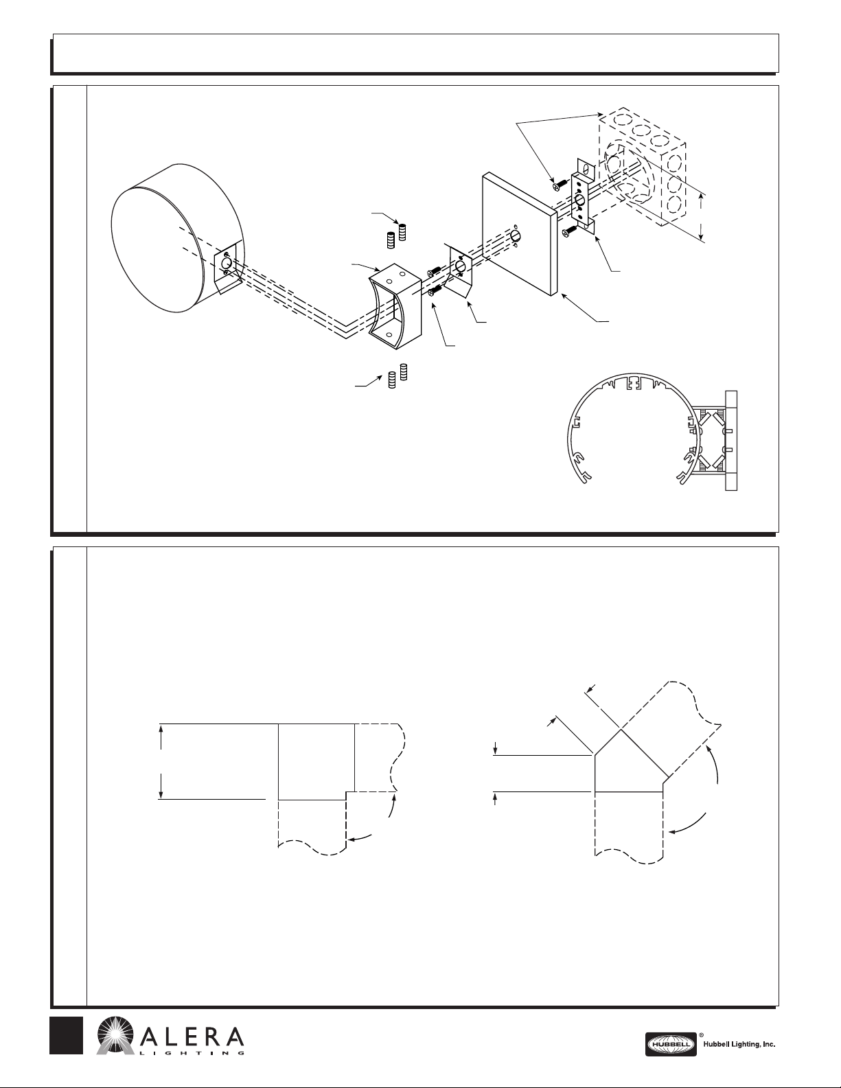
IT6 WALL MOUNT
Junction box, plaster ring,
and mounting screws by
installing contractor
ONNECTIONS
C
IXTURE
F
1) Attach wall bracket to plaster ring using plaster ring screws. (Pull service
2) Attach wall plate and wall cleat to wall bracket with two #10-24 X .500
3) Secure support arm to wall cleat by driving two 1⁄4
4) Make service lead connection to ballast leads and ground inside fixture.
Set screws
Support arm
Set screws
through center hole)
round head machine screws provided.
-20 X .500 recessed
socket head set screws (provided with kit) behind flanges of wall cleat.
Wall cleat
Screw #10-24 .500
Wall bracket
Wall plate
3
⁄4″ plaster
2
ring
mounting
IMENSIONS
D
ORNER
C
2-6
T
90° 135°
8″
90°
701 Millennium Blvd
Greenville SC 29607 • (864) 678-1000
www.aleralighting.com
We are architectural fluorescent lightin
41⁄2″
Subject to change without notice.
41⁄2″
135°
AL 10/07
 Loading...