


TECHNICAL INSTALLATION DATA
ECTIONS
S
IEW
V
OTTOM
B
SINGLE MOUNTING
9
9
/16″
CROSS SECTION
ALL PERFORATED HOUSING
31/8″
CONNECTION SECTION
PERFORATED BOTTOM
D
ROW MOUNTING
DATA CHART
A
4, 8, 12 ft.
C
ABBB
4, 8, 12 ft.
Nominal Approx. Weight ABCD
Length 2-lamp
A
B
CD
4′ 16.1 lbs. 471⁄2″ 48″ 1921⁄8″ 481⁄8″
8′ 27.6 lbs. 951⁄2″ 96″ 3841⁄8″ 961⁄8″
12′ 39.1 lbs. 1431⁄2″ 144″ 5761⁄8″ 1441⁄8″
Note: Suspension data is computed using the standard aircraft cable assembly. The use of rigid stems will
yield different data. Please consult factory for stem data.
701 Millennium Blvd
www.aleralighting.com
Subject to change without notice.
Greenville SC 29607 • (864) 678-1000
We are architectural fluorescent lighting
12-3.1
C
TECHNICAL INSTALLATION DATA
g
ONNECTIONS
C
ALL PERFORATED HOUSING
IXTURE
F
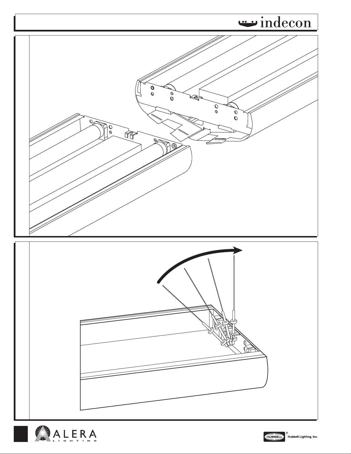
Suspension Instructions:
1. Set bottom nut to desired fixture
height.
2. Adjust upper nut for a minimum of
between upper and lower nuts.
3. Slide cable hanger into hanger slot.
4. Secure and tighten upper nut.
Connection Instructions:
1. Install first fixture of row with two hangers.
2. Engage the aligner fingers at the joint by
rotating the next fixture into position and
then attaching hanger.
3. Secure and adjust fixture joints with two
bolts and nuts.
4. Repeat steps 2 and 3 until row is
complete.
5. At the end of the row, bend the three
aligner fingers into the fixture housing.
6. Attach and align end cap with 2 nuts.
3
/8″
TTACHMENT
A
USPENSION
S
12-3.1
C
701 Millennium Blvd
Greenville SC 29607 • (864) 678-1000
www.aleralighting.com
We are architectural fluorescent lightin
AL AL 08/07
Subject to change without notice.
 Loading...