

Alera Lighting ASC User Manual
TECHNICAL INSTALLATION DATA
″
21/2″
ASC,
ECTIONS
S
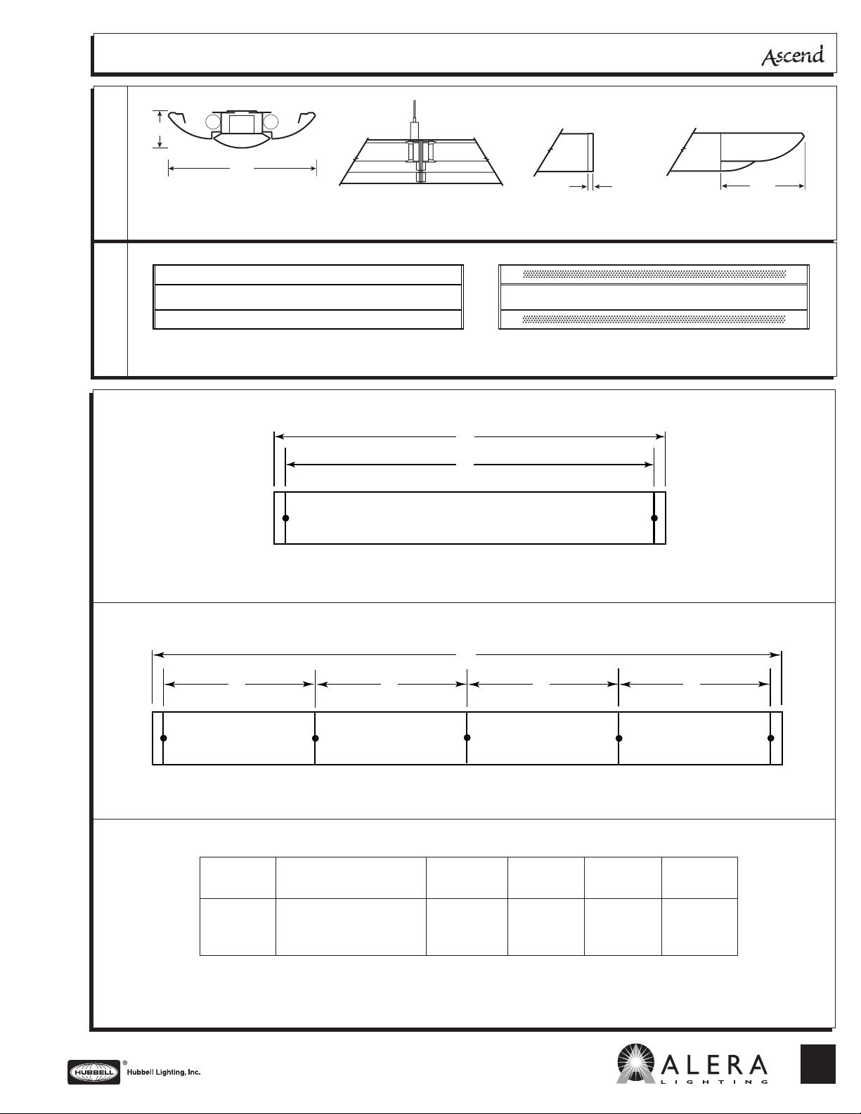
ASC-2T8
CROSS SECTION
IEW
V
OTTOM
B
SINGLE MOUNTING
10″
CONNECTION SECTION
D
A
4, 8 ft.
5
/
16
3
5
/8″
FLAT END CAP SCULPTED END CAP
PERFORATED WINGSOLID WING
ROW MOUNTING
DATA CHART
C
ABBB
4, 8 ft.
Nominal Approx. Weight AB CD
Length 2-lamp
4′ 11 lbs. 471⁄4″ 48″ 1925⁄8″ 485⁄8″
8′ 20 lbs. 951⁄4″ 96″ 3845⁄8″ 965⁄8″
Note: Suspension data is computed using the standard aircraft cable assembly and flat end caps. The use of rigid stems
will yield different data. Please consult factory for stem data.
A
B
CD
Greenville SC 29607 • (864) 678-1000
Subject to change without notice.
We are architectural fluorescent lighting
701 Millennium Blvd
www.aleralighting.com
19-1.1
C
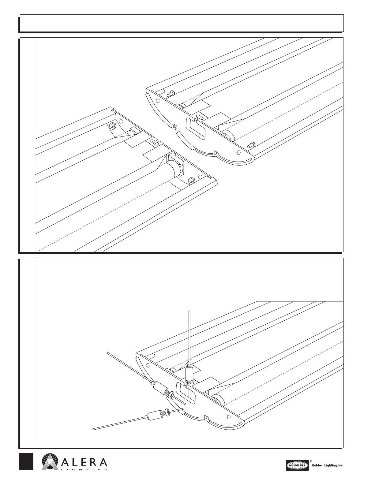
TECHNICAL INSTALLATION DATA
g
ONNECTIONS
C
IXTURE
F
Connection Instructions:
1. Install first fixture of row with two hangers.
2. Place bolts through openings in internal
end cap.
3. Slide other fixture onto bolts and attach nuts.
4. Repeat steps 2 and 3 until row is complete.
5. At each end of the row, attach and align end
cap with appropriate nuts.
Suspension Instructions for
Adjustable or Fixed Hanger:
1. Move nut to bottom of cable assembly.
2. Slide cable hanger into slot on inner
end plate.
3. Pull up on cable assembly and rotate
clockwise to tighten. (Secure and
tighten upper nut on fixed hangers.)
4. For horizontal adjustment, slide
hanger in slot on inner end plate.
TTACHMENT
A
USPENSION
S
19-1.1
C
701 Millennium Blvd
Greenville SC 29607 • (864) 678-1000
www.aleralighting.com
We are architectural fluorescent lightin
AL 08/07
Subject to change without notice.
 Loading...