

A+CLASS™ TeACher LighTing ConTroL STATion
Description
The A+CLASS™ Teacher Lighting Control Station switches are
designed to provide a user interface and control of systems
operating on Class 2, low voltage circuitry. The Teacher Lighting
Control station switches are provided as part of the A+CLASS™
system. See INCLUDED COMPONENTS below for additional
component details. A separate whiteboard switch is an optional
auxiliary component for the TLC (Teacher Lighting Control) station.
speciFicAtions
• Electrical Ratings: Each switch: 100mA @ 30VDC Max
• Accepts standard decorator style wall plate, switch plate provided
• UI and cUL listed when installed as part of a complete A+Class™
System
• 5-year warranty when installed as part of a complete A+Class™
System
TLC
Technical Installation Data
TLC Back View
precAUtions
• CAUTION: FOR USE WITH CLASS 2, LOW VOLTAGE SYSTEMS
ONLY. DO NOT USE IN HIGH VOLTAGE APPLICATIONS.
• Read and understand all instructions before beginning
installation.
• NOTICE: For installation by a licensed electrician in accordance
with National and/or local Electrical Codes.
• NOTICE: For indoor use only.
• CAUTION: USE COPPER CONDUCTOR ONLY.
• Conrm device ratings are suitable for application prior to
installation. Use of device in applications beyond its specied
ratings or in applications other than its intended use may cause
an unsafe condition and will void manufacturer’s warranty.
• NOTICE: Do not install if any damage to product is noticed.
• ALL EXCESS CAT5 CABLE MUST BE REMOVED FROM WALL BOX
PRIOR TO INSTALLATION. Connection between CAT5 cable and
switch connection port must remain straight and true without
interference or pressure from excess or misaligned cable.
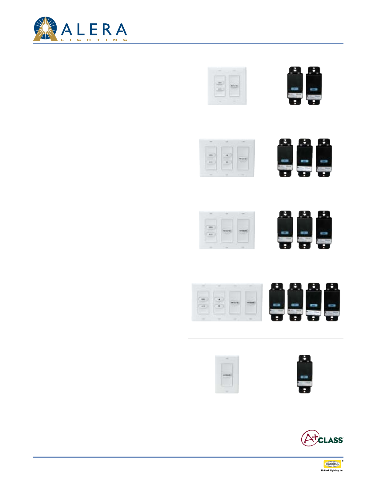
incLUDeD coMponents
1. Classroom Control Module (CCM)
2. Teacher Lighting Control Station Switches
• GEN / A/V – Standard. Two buttons (GEN and A/V) switch
between General Lighting and Audio Visual Lighting.
• Study Time with LED indicator – Standard. Occupancy Sensor
override switch (set standard for 60 minute override)
• A/V Dimming (Chevron Up/Chevron Down) – Optional.
Pressing Chevron Down will manually lower light level in
increments when in the A/V mode. Pressing Chevron Up will
manually raise light level in increments when in the A/V mode.
Requires 0-10V ballasts in the primary lighting xtures in the
room in order to operate properly. Operates in the A/V mode
only. To test, press A/V switch, ensure A/V mode is engaged,
then press Chevron Down to lower light level and Chevron
up to raise light level. Not applicable on whiteboard lighting
xtures if whiteboard xtures are used in the classroom.
TLC-AVD
TLC-WT
TLC-AVD-WT
WS Button
when installed as a
separate switch station
TLC-AVD Back View
TLC-WT Back View
TLC-AVD-WT Back View
WS Back View
Page 1/3 Rev. 08/0 4/13 H72- 00434 INTEGRATED CONTROLS / A+CLASS™ APCS TLC TID
© 2013 Ale ra Lighting, a division of Hubbell Lighting , Inc. Because of co ntinuing product im provement programs, A lera Lighting reser ves the right to change specifications
without notice. 701 Millennium Blvd. Greenville, SC 29607 / Tel 864.678.1000 / Website www.aleralightin g.com
US Patent #8,436,542
A+CLASS™ TeACher LighTing ConTroL STATion
Technical Installation Data
• Whiteboard on/o – Optional. If dedicated whiteboard lighting has been installed in the classroom, the switch will turn the whiteboard
lighting on and o. For rooms with multiple whiteboards and multiple dedicated whiteboard lighting, consult wiring diagram.
3. 50' Blue CAT5 Cable
• One per Teacher Lighting Control Station
• One per Row single or ganged switch station
4. 3" Blue CAT5 Jumper Cable
• One per each jump required. Number provided will be determined by the TLC conguration the customer has ordered.
2-Gang: Gen / A/V and Study Time switch gang: 1 jumper
3-Gang: Gen / A/V, Study Time and either Whiteboard or A/V dimming: 2 jumpers
4-Gang: Gen / A/V, Manual A/V Dimming, Whiteboard and Study Time: 3 jumpers
• If multiple Teacher Lighting Control stations are used, the appropriate number of jumpers will be provided.
5. Decorator Style Switch Plate(s) for 2, 3 or 4-gang TLC stations as dictated by customer order.
6. A separate, optional Whiteboard switch may also be included for on/o control of dedicated whiteboard lighting. If this option has been
ordered, it will include 50’ of blue CAT5 cable, a separate whiteboard switch, and a single gang decorator style switch plate.
7. A+CLASS™ lighting xtures (shipped separately)
teAcher Lighting controL (tLc) stAtion switch iDentiFicAtion
Part No.
APCS-TLC-GAV
Standard Feature
APCS-TLC-ST
Standard Feature
APCS-TLC-AVD
Optional Feature
APCS-WS
Optional Feature
APCS-WS (WI)
Optional Feature
Back
Label
GAV 2
ST 1 STUDY TIME
AVD 2
WS 1 WHITEBOARD
WS 1 WHITEBOARD
No. of
Buttons
Switch
Button(s) Function
GEN
A/V
GEN: Switches General Lighting mode on, switches A/V Lighting mode o
A/V: Switches A/V Lighting mode on, switches General Lighting mode o.
Overrides occupancy sensor for 60 minutes standard (time may be adjusted in
CCM programming menu). When LED is lit, STUDY TIME is engaged. When LED
light goes o, lighting defaults to Occupancy Sensor control and will turn o if
the room is unoccupied.
In A/V mode ONLY, raises or lowers light level. Requires 0-10V dimming ballast
in A+CLASS lighting xture. Does not operate whiteboard lighting.
Provides on/o control for dedicated whiteboard lighting with switch installed
in the TLC.
Provides on/o control for dedicated whiteboard lighting. When ordered as WI
option, the switch is not installed in the TLC and is shipped with an extra 50’
blue cable and a 1-gang switch plate.
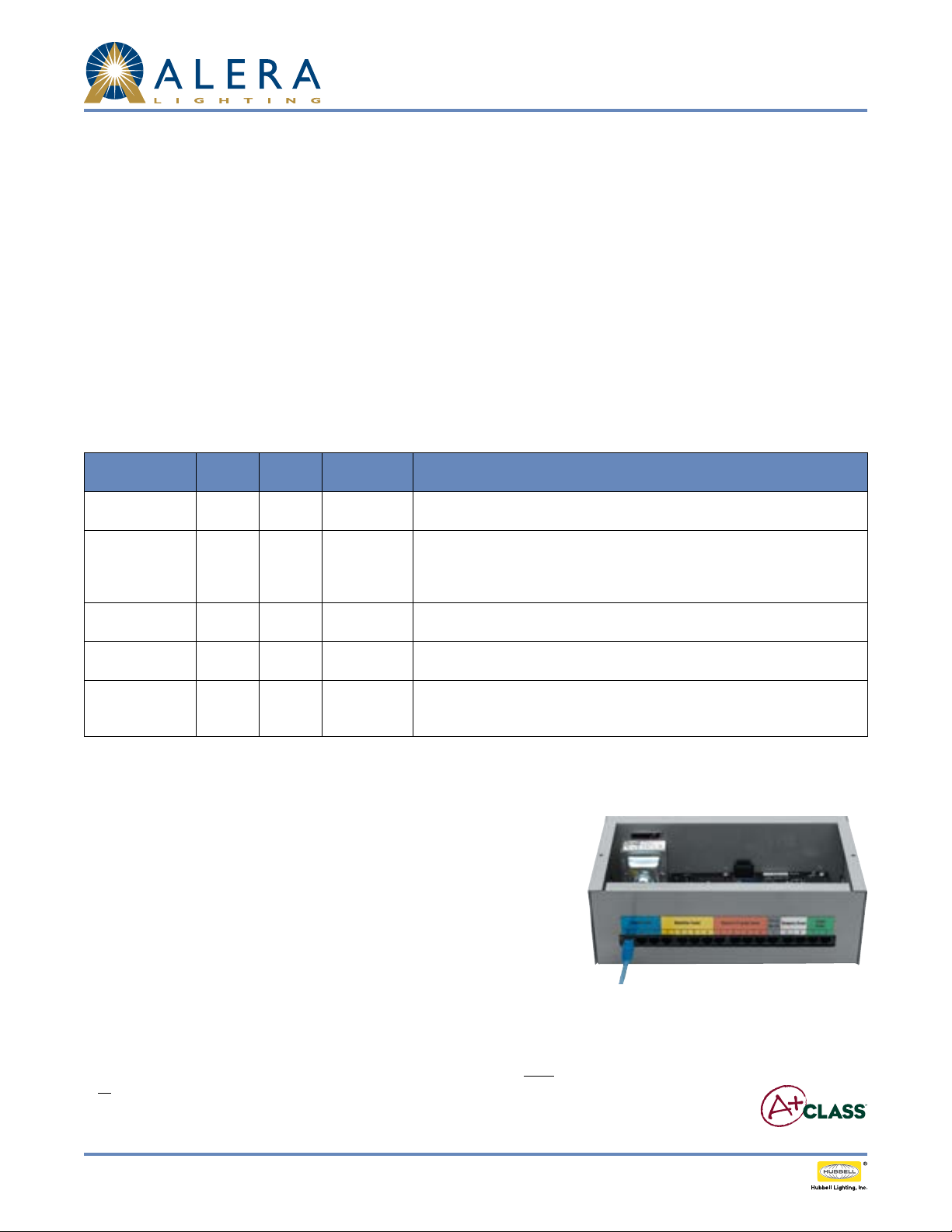
instALLAtion instrUctions
1. Prepare the installation site, as necessary, to install the switch.
2. Plug the 50' Blue CAT5 cable into the Blue Teacher Station connector on the
Classroom Control Module (See Figure 1). Each CAT5 connection will operate
properly from any of the three available blue Teacher Station Control port. Multiple
connections are required under the following circumstances.
a. When multiple Teacher Lighting Control stations are used and each has a home
run back to the CCM.
b. When one Teacher Lighting Control station is used in conjunction with a one or
more separate whiteboard switches and each has a home run back to the CCM.
c. When two Teacher Lighting Control stations are used with one whiteboard switch
and each has a home run back to the CCM.
4. Route the Blue cable from the Classroom Control Module (CCM) to the Teacher
Lighting Control Station(s) and/or separate Whiteboard switch(es). If routing
multiple switch stations and/or multiple individual whiteboard controls, up to three
connections may be made as home run connections. Note: Low voltage wiring must
be isolated from line voltage wiring. Consult National and Local Electrical Codes for
conduit requirements.
Fig. 1
Page 2 /3 Rev. 08/04/13 H72-00 434 INTEGRATED CONTROLS / A+CLASS™ APCS TLC TID
© 2013 Ale ra Lighting, a division of Hubbell Lighting , Inc. Because of co ntinuing product im provement programs, A lera Lighting reser ves the right to change specifications
without notice. 701 Millennium Blvd. Greenville, SC 29607 / Tel 864.678.1000 / Website www.aleralightin g.com
US Patent #8,436,542

A+CLASS™ TeACher LighTing ConTroL STATion
5. Plug the Blue cable into any CAT5 connection port on the back of any switch in the
Teacher Lighting Control Station (See Figure 2). Verify solid snap-in connection.
6. In each TLC, multiple switches are ganged together. Make connections between
switches; daisy-chain them together using the 3" Blue jumper cable (See Figure 3).
Verify solid snap-in connections.
7. Remove excess CAT5 cable from wall box prior to insertion of switch(es). CAT5
connection to switch must remain straight, true, and free of pressure or interference
from excess in box. Test functionality of switch prior to installing the switches into
the electrical box. (See Figure 4)
8. Perform system setup and/or programming activities as applicable in accordance
with the instructions of the CCM (Classroom Control Module).
9. Verify switch functionality by pressing the switch button(s) and conrm proper
system response.
NOTE: EasyConnect cord upgrade may be provided. EasyConnect can be
identied in Figure 5 below.
Technical Installation Data
Fig. 2
troUbLeshooting tips
1. Check for solid connections between all components.
2. Ensure power to CCM is engaged.
3. Ensure wall box does not include excess cable; CAT5 connections must be straight
and true without interference. See step 6 above.
4. For optional A/V Dimming, if applicable, verify A+CLASS™ lighting xtures have
0-10V dimming ballasts installed.
5. Consult CCM programming manual for additional assistance.
Fig. 3
a
Fig. 4
A B
(Cat cable end may look like A or B)
Fig. 5
Page 3/3 Rev. 08/04/13 H72-0 0434 INTEGRATED CONTROLS / A+CLASS™ APCS TLC TID
© 2013 Ale ra Lighting, a division of Hubbell Lighting , Inc. Because of co ntinuing product im provement programs, A lera Lighting reser ves the right to change specifications
without notice. 701 Millennium Blvd. Greenville, SC 29607 / Tel 864.678.1000 / Website www.aleralightin g.com
US Patent #8,436,542
 Loading...