

Alera Lighting APCS MRCS User Manual
A+CLASS™ MASter/row ControL SwitCh
Technical Installation Data
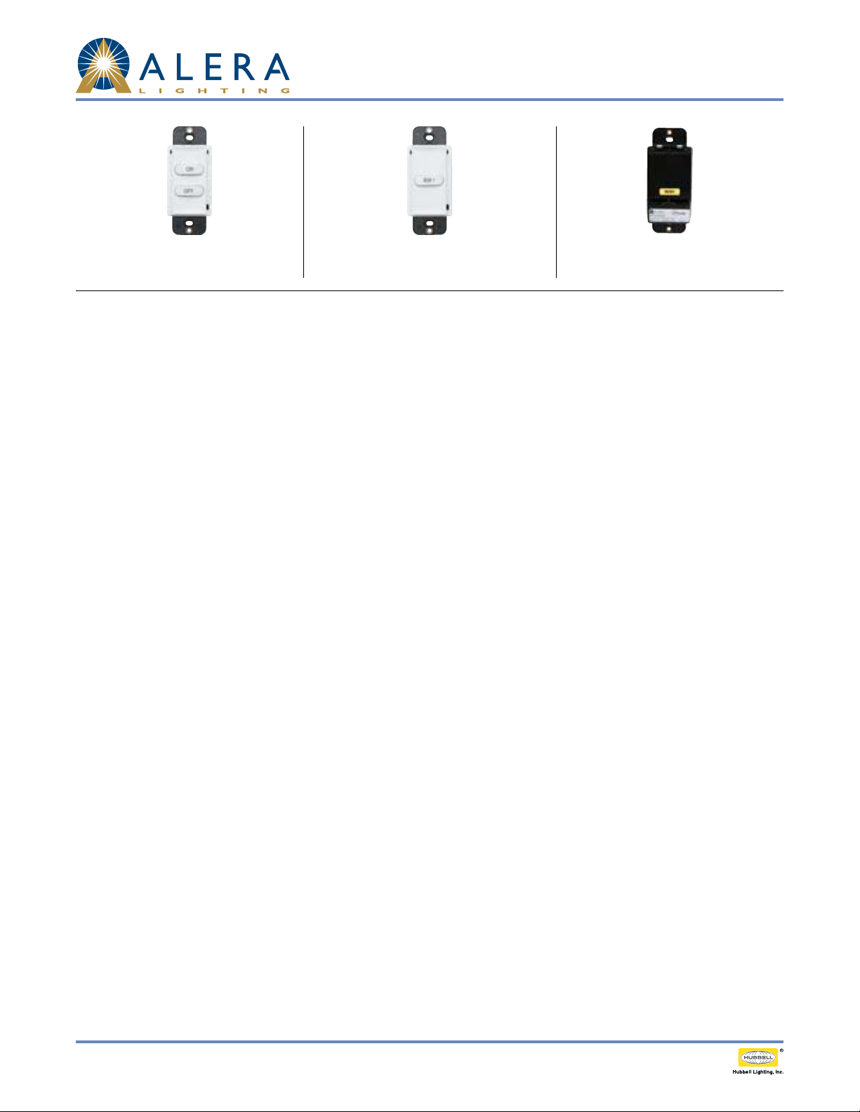
Fig. M - Front of Master On/O Switch Fig. R - Front of Row On/O Switch
Fig. B - Back of Switch without cables
Example shown: Row 1 Switch
Description
The A+CLASS™ Master Control and Row Control Switches are designed to provide a user interface and on/o control of systems operating on
Class 2, low voltage circuitry. Master and/or Row Control Switches are provided as part of the A+CLASS™ system. See INCLUDED COMPONENTS
below for additional switch station component information. Congurations of A+CLASS™ Master and/or Row Control switches are provided
based on customer order.
speciFicAtions
• Electrical Ratings: Each switch: 100mA @ 30VDC Max
• Accepts standard decorator style wall plate, provided with A+CLASS™ system
• UL and cUL listed when installed as part of a complete A+Class™ System
• 5-year warranty when installed as part of a complete A+Class™ System
precAUtions
• CAUTION: FOR USE WITH CLASS 2, LOW VOLTAGE SYSTEMS ONLY. DO NOT USE IN HIGH VOLTAGE APPLICATIONS.
• Read and understand all instructions before beginning installation.
• NOTICE: For installation by a licensed electrician in accordance with National and/or local Electrical Codes.
• NOTICE: For indoor use only.
• CAUTION: USE COPPER CONDUCTOR ONLY.
• Conrm device ratings are suitable for application prior to installation. Use of device in applications beyond its specied ratings or in
applications other than its intended use may cause an unsafe condition and will void manufacturer’s warranty.
• NOTICE: Do not install if any damage to product is noticed.
• ALL EXCESS CAT5 CABLE MUST BE REMOVED FROM WALL BOX PRIOR TO INSTALLATION. Connection between CAT5 cable and switch
connection port must remain straight and true without interference or pressure from excess or misaligned cable.
incLUDeD coMponents
1. Classroom Control Module (CCM)
2. Switch Stations
• Master On/O: Turns all rows of lighting on or o from a single switch
• Row 1, Row 2, Row 3, Row 4: Turns one row of lighting on or o. Each row requires a separate switch. A+CLASS will support up to four
individual rows of lighting. Row controls are typically ganged together with only one home run back to the CCM per gang.
3. 50' Yellow CAT5 Cable
• One per Master On/O switch station
• One per Row single or ganged switch station
4. 3" Yellow CAT5 Jumper Cable (Row Gangs Only)
• Not required for Master On/O switch station
• One per each jump required
• 2-Row switch gang: 1 jumper
• 3-Row switch gang: 2 jumpers
• 4-Row switch gang: 3 jumpers
• If multiple Row stations are used, the appropriate number of jumpers will be provided
5. Switch Plate(s) for single or multi-gang as dictated by customer order
6. A+CLASS™ lighting xtures (shipped separately)
Page 1 /2 Rev. 08/05/13 H72- 00435
© 2013 Ale ra Lighting, a division of Hubbell Lighting , Inc. Because of continuing product improvement pro grams, Alera Lighting reserves the right to ch ange specifications
without notice. 701 Millennium Blvd. Greenville, SC 29607 / Tel 864.678.1000 / Website ww w.aleralighting.com
US Patent #8,436,542
Integrated Controls / A+CLASS™ MASTER/ROW CONTROL SWITCH TID

switch stAtion iDentiFicAtion
A+CLASS™ MASter/row ControL SwitCh
Technical Installation Data
Side Label
P/N Back Label
APCS-MC MC 2 ON, OFF On/O control for all rows of general and/or A/V lighting
APCS-RCR1 RCR1 1 ROW 1 On/O control for one row of general and/or A/V lighting designated Row 1
APCS-RCR2 RCR2 1 ROW 2 On/O control for one row of general and/or A/V lighting designated Row 2
APCS-RCR3 RCR3 1 ROW 3 On/O control for one row of general and/or A/V lighting designated Row 3
APCS-RCR4 RCR4 1 ROW 4 On/O control for one row of general and/or A/ V lighting designated Row 4
No. of
Buttons
Button
Label(s) Function
instALLAtion instrUctions
1. Prepare the installation site, as necessary, to install the switch.
2. Plug the 50' Yellow CAT5 cable into the Yellow Master/Row Control connector on the
Classroom Control Module (See Figure 1). Each CAT5 connection will operate properly from
any available Yellow Master/Row Control port. Multiple connections are required under the
following circumstances.
a. When multiple Master On/O controls are used and each has a home run back to the CCM.
b. When a Master On/O control is used in conjunction with a gang of Row on/o controls.
c. When multiple Row control gangs are used in the same classroom and each has a home run
back to the CCM.
3. Route the Yellow cable from the Classroom Control Module to the Master Control Switch or
Row Control Switch. If routing multiple switch stations, up to four connections may be made
as home run connections. Note: Low voltage wiring must be isolated from line voltage wiring.
Consult National and Local Electrical Codes for conduit requirements.
Fig. 1
4. Plug the Yellow cable into the Master Control Switch or Row Control Switch (See Figure 2).
Verify solid snap-in connection.
5. If multiple switches are ganged together, daisy-chain them together using 3" Yellow jumper
cable (See Figure 3). Verify solid snap-in connection(s).
6. Remove excess cable from wall box prior to insertion of switch(es). CAT5 connection to the
switch must remain straight, true, and free of pressure or interference from excess cable
in box. (See Figure 4). Test functionality of switch prior to installing the switches into the
electrical box.
7. Perform system setup and/or programming activities as applicable in accordance with the
instructions of the CCM (Classroom Control Module).
8. Verify switch functionality by pressing the switch button(s) and conrm proper system
response.
note: Ea syConnect cord u pgrade may be provided . EasyConnect c an be identified in Fig ure 5 .
troUbLeshooting tips
1. Check for solid connections between all components.
2. Ensure power to CCM is engaged.
3. Ensure wall box does not include excess cable; CAT5 connections must be straight and true
without interference. See step 6 above.
4. Consult CCM programming manual for additional assistance.
Fig. 2
a
Fig. 4
A B
1. (Cat cable end may look like A or B)
Fig. 5
Fig. 3
Page 2 /2 Rev. 08/05/13 H72-00 435
© 2013 Ale ra Lighting, a division of Hubbell Lighting , Inc. Because of continuing product improvement pro grams, Alera Lighting reserves the right to ch ange specifications
without notice. 701 Millennium Blvd. Greenville, SC 29607 / Tel 864.678.1000 / Website ww w.aleralighting.com
US Patent #8,436,542
Integrated Controls / A+CLASS™ MASTER/ROW CONTROL SWITCH TID
 Loading...