

Alera Lighting APCS DS User Manual

A+CLASS™ DAyLight SenSor
Technical Installation Data
Description
The A+CLASS™ Daylight Sensor provides daylight level information to the Classroom Control Module. The Daylight Sensor continuously
measures daylight levels and sends this information to the Classroom Control Module.
speciFicAtions
• Supply voltage (supplied by Classroom Control Module): 24VDC
• UL and cUL listed when installed as part of a complete A+Class™ System
• 5-year warranty when installed as part of a complete A+Class™ System
precAUtions
• CAUTION: FOR USE WITH CLASS 2, LOW VOLTAGE SYSTEMS ONLY. DO NOT USE IN HIGH VOLTAGE APPLICATIONS.
• Read and understand all instructions before beginning installation.
• NOTICE: For installation by a licensed electrician in accordance with National and/or local Electrical Codes.
• NOTICE: For indoor use only.
• CAUTION: USE COPPER CONDUCTOR ONLY.
• Conrm device ratings are suitable for application prior to installation. Use of device in applications beyond its specied ratings or in
applications other than its intended use may cause an unsafe condition and will void manufacturer’s warranty.
• NOTICE: Do not install if any damage to product is noticed.
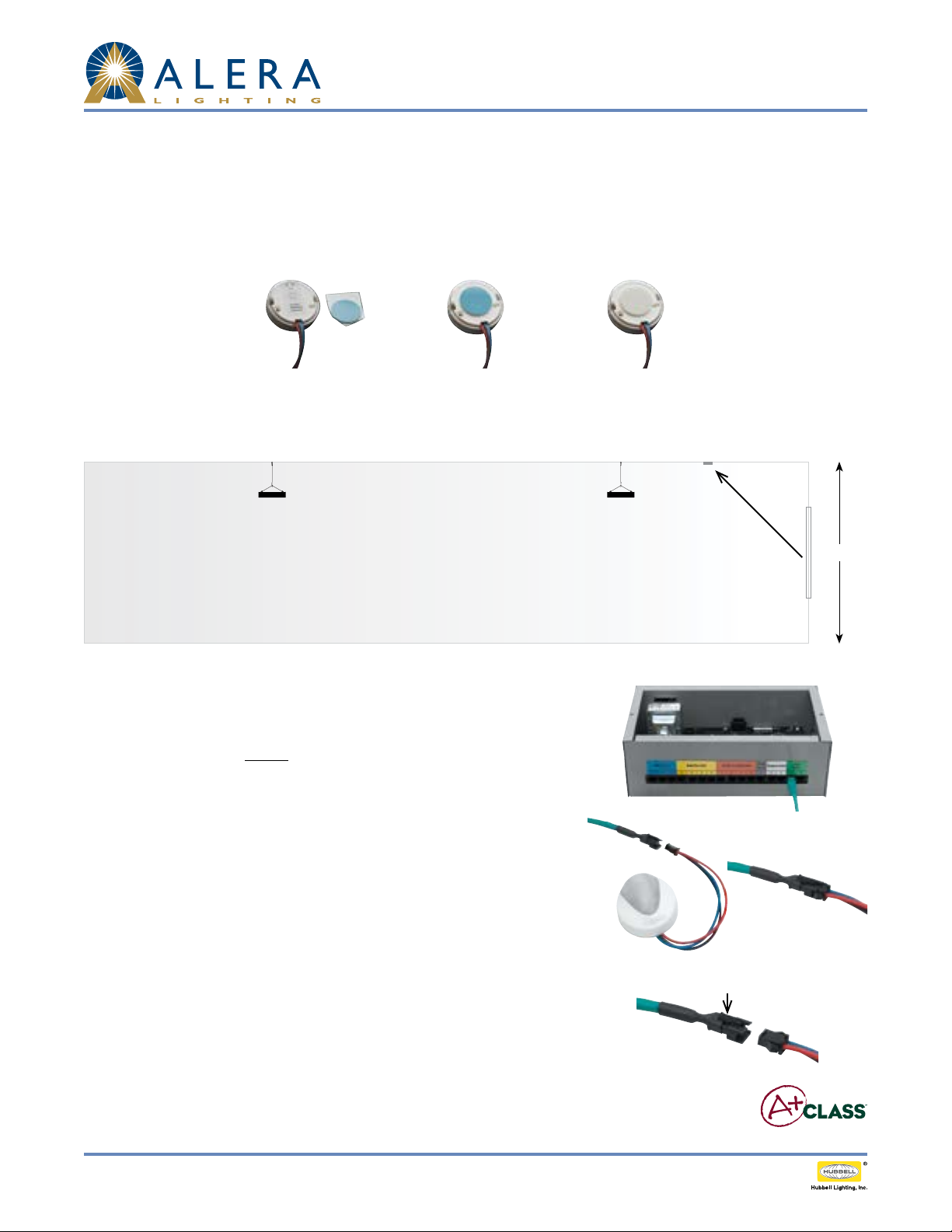
incLUDeD coMponents
1. Classroom Control Module (CCM)
2. 50' Green low voltage cable
with CAT5 connection on one end and snap-in connection which mates to Daylight Sensor on the other end (See Figures 1 and 1a).
3. Daylight Sensor with pre-installed low voltage Quick–To-Install™ (QTI) connector. The sensor’s QTI connector quickly mates to the
snap-in QTI connection on Green low voltage cable, also provided (See Figure 2).
4. A+CLASS™ Lighting xtures with 0-10V dimming ballasts installed for the General lighting mode.
DAYLiGHt sensor pLAceMent
The Daylight Sensor must be placed to see only daylight with no contribution from articial light sources. The sensor typically mounts on the
ceiling between the window and the row of xtures closest to the window. For skylight applications, the sensor mounts in the lightwell. The
sensor is aimed toward the daylight. A light meter is required for light level measurements at the task areas (See Figure 3).
Window
Point
towards
daylight
Fig. 1
Fig. 2
A B
(Cat cable end may look like A or B)
Fig. 3
Fig. 1a
Page 1/3 Rev. 07/16/13 H72-0 0437 INTEGRATED CONTROLS / A+CLASS™ APCS DS TID
© 2013 Ale ra Lighting, a division of Hubbell Lighting , Inc. Because of co ntinuing product im provement programs, A lera Lighting reser ves the right to change specifications
without notice. 701 Millennium Blvd. Greenville, SC 29607 / Tel 864.678.1000 / Website www.aleralightin g.com
US Patent #8,436,542
A+CLASS™ DAyLight SenSor
Technical Installation Data
instALLAtion instrUctions
1. The sensor’s foot candle range is set via a jumper switch. Default setting: 30 – 3000 FC (Typical for most applications). If the sensor’s range
needs to be changed, pry cover o using a screwdriver and set jumper switch accordingly. It is recommended that prior to changing the
default setting, rst set up the A+CLASS program for Daylighting in the Classroom Control Module (CCM) and verify that a dierent range
is needed. Refer to CHANGING DAYLIGHT SENSOR SETTINGS below if change is necessary.
2. Apply mounting tape to back of sensor (See Figures 4a, 4b and 4c).
Fig. 4a Fig. 4cFig. 4b
3. Attach sensor to ceiling, wall or skylight. Note: Peak sensitivity is achieved when sensor is placed at a 45 degree angle to window
(See Figure 5). When used with skylight, point sensor (lensed area) up towards daylight rather than down towards room.
Daylight Sensor lens aimed at window
Fig. 5
4. Plug the 50' Green CAT5 cable into either of the two available Green connector ports on
the Classroom Control Module (See Figure 6).
5. Route the Green cable from the Classroom Control Module to the Daylight Sensor.
Note: Low voltage wiring must be isolated from line voltage wiring. Consult National
and Local Electrical Codes for conduit requirements.
6. Plug the Green cable into the Daylight Sensor’s QTI connector (See Figures 7a and 7b).
7. Perform system setup and/or programming activities as applicable in accordance with
the instructions of the Classroom Control Module.
8. Verify Daylight Sensor functionality by checking System Status/Daylight Sensor on the
Classroom Control Module. Real-time foot candle levels will be displayed if operating
properly. If foot candle levels do not change, check connectivity at wiring to CCM,
Daylight Sensor and light xture. Verify A+CLASS lighting products include installed
0-10V dimming ballasts.
9. If desired, to disconnect Daylight Sensor from Green CCM cable, press down on the
upper tab on the connection (located on the Green cable side of the QTI connector).
Gently pull the two sides of the QTI connector apart (See Figure 8).
45° angle from daylight window
to Daylight Sensor with
Fig. 6
Fig. 7a
Press down on tab to disconnect
10'
Fig. 7b
10. The sensor’s foot candle range is set via a jumper switch. Default setting: 3-300 FC
(Typical for most applications). If the sensor’s range needs to be changed, pry cover o
using a screwdriver and set jumper switch accordingly. It is recommended that prior to
Fig. 8
changing the default setting, rst set up the A+CLASS™ program for Daylighting in the
Classroom Control Module (CCM) and verify that a dierent range is needed.
Page 2 /3 Rev. 07/16/13 H72-00 437 INTEGRATED CONTROLS / A+CLASS™ APCS DS TID
© 2013 Ale ra Lighting, a division of Hubbell Lighting , Inc. Because of co ntinuing product im provement programs, A lera Lighting reser ves the right to change specifications
without notice. 701 Millennium Blvd. Greenville, SC 29607 / Tel 864.678.1000 / Website www.aleralightin g.com
US Patent #8,436,542
 Loading...