

sections
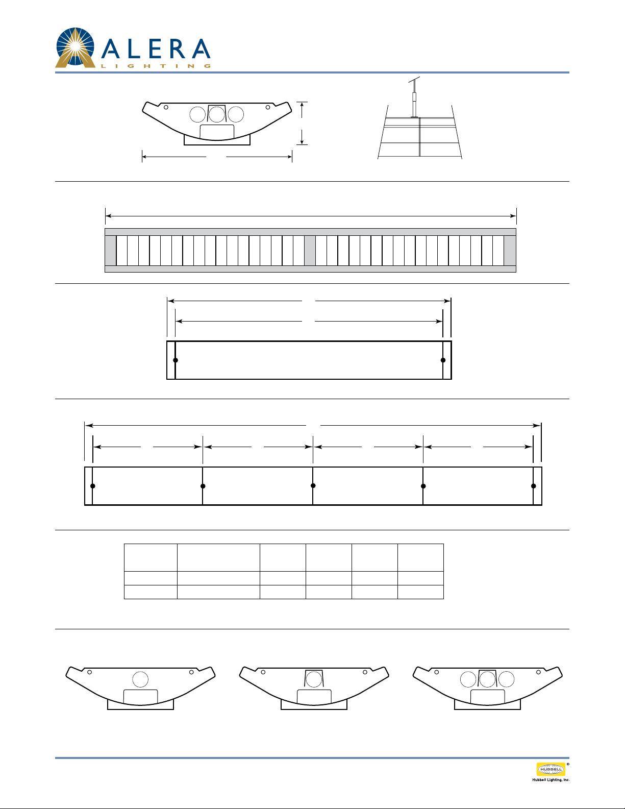
BottoM View
Curv Louvered - A+CLASS
Technical Installation Data
2¾"
9½"
Connection SectionCross Section
8'
single Mounting
Row Mounting
A B B B
data chaRt
Nominal
Length
Note: Suspension data is computed using the standard aircraft cable assembly. The use of rigid stems will yield dierent data. Please consult
factory for stem data. *3-Lamp includes CLC cover.
D
A
4', 8', 12'
C
4', 8', 12'
Approx. Weight
3-lamp*
4' 19 lbs. 47 ¼" 48" 192 ⅝" 48 ⅝"
8' 31 lbs. 95 ¼" 96" 384 ⅝" 96 ⅝"
A B C D
to install a/V downlight coVeR:
» »
1. Install center lamp. 2. Place A/V cover directly over center lamp. 3. Install outer lamps.
Page 1 /4 Rev. 07/15/13 curves / CVL-APCS TID
© 2013 Ale ra Lighting, a division of Hubbell Lighting, Inc. B ecause of continuing product imp rovement programs, Al era Lighting reserves the right to change specific ations
without notice. 701 Millennium Blvd. Greenville, SC 296 07 / Tel 864.678.1000 / Website www.aleralighting.com
US Patent #8,436,542
Curv Louvered - A+CLASS
18-7.1
Technical Installation Data
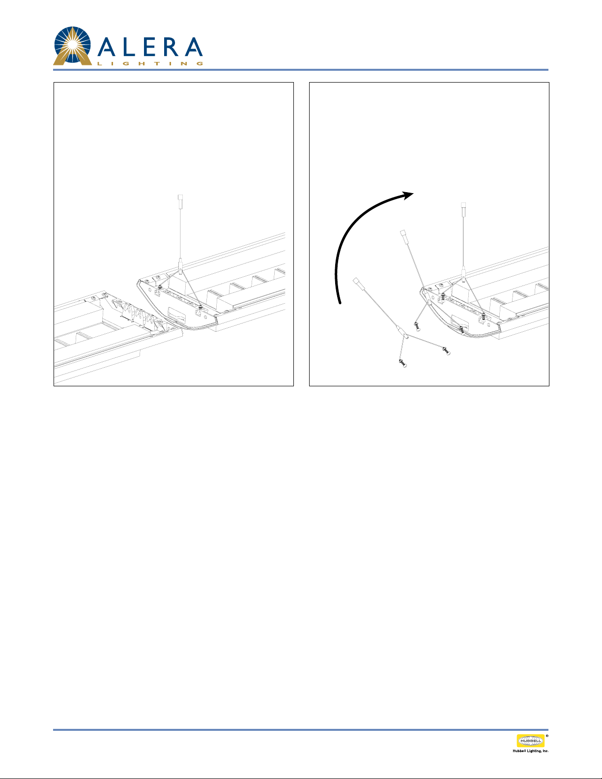
Connection Instructions:
1. Install rst xture of row with two hangers.
2. Slide inner die cast plates together.
3. Secure xture joints with two bolts and nuts
and attach hanger at opposite end.
4. Repeat steps 2 and 3 until row is complete.
5. At each end of the row, attach and align end
cap with two screws.
3-Lamp
Cross Sections
Suspension Instructions:
1. Set bottom nut to desired xture height.
2. Adjust upper nut for a minimum of ⅜"
between upper and lower nuts.
3. Slide cable hanger into hanger slot.
4. Secure and tighten upper nut.
3-Lamp
Cross Sections
Page 2 /4 Rev. 07/15/13 curves / CVL-APCS TID
© 2013 Ale ra Lighting, a division of Hubbell Lighting, Inc. B ecause of continuing product imp rovement programs, Al era Lighting reserves the right to change specific ations
without notice. 701 Millennium Blvd. Greenville, SC 296 07 / Tel 864.678.1000 / Website www.aleralighting.com
US Patent #8,436,542

a+class 4 Rows, no wBd 120V
Curv Louvered - A+CLASS
Technical Installation Data
CCM
BACK
Line voltage wiring from luminaire row(s) to
GROUND
NEUTRAL
277VAC
120VAC
NEUTRAL
LINE
120\277VAC
INPUT
LIGHTING
BATTERY TYPE BR2032
INSERT
INSERT SD CARD
CIRCUITPOWER TO CONTROLLER
GENERAL
NEUTRAL
A/V
GENERAL
NEUTRAL
A/V
GENERAL
NEUTRAL
A/V
GENERAL
SELECT
NEUTRAL
A/V
WHT BRD
NEUTRAL
WHITE BOARDROW 4ROW 3ROW 2ROW 1
GROUND
NEUTRAL
277VAC
120VAC
NEUTRAL
LINE
120\277VAC
INPUT
LIGHTING
CIRCUITPOWER TO CONTROLLER
GENERAL
NEUTRAL
A/V
GENERAL
NEUTRAL
A/V
GENERAL
NEUTRAL
A/V
GENERAL
NEUTRAL
A/V
WHT BRD
NEUTRAL
WHITE BOARDROW 4ROW 3ROW 2ROW 1
Main Power Feed
Classroom Control Module (CCM) per federal,
state, and local codes. Licensed electrical
contractor is required for installation. Proper
installation is the responsibility of the installing
electrical contractor.
To dual circuit
A+CLASS™
Lighting Row 1
To dual circuit
A+CLASS™
Lighting Row 2
To dual circuit
A+CLASS™
Lighting Row 3
To dual circuit
A+CLASS™
Lighting Row 4
CAUTION: Before applying power to the Classroom Control Module (CCM) verify input voltage has been wired to the proper input
and output relays. IMPROPERLY APPLIED VOLTAGE WILL DAMAGE CCM AND VOID WARRANTY.
For low voltage connections to CCM see Quick Start Guide and/or APCS-LV-INSTR.
Page 3 /4 Rev. 07/15/13 curves / CVL-APCS TID
© 2013 Ale ra Lighting, a division of Hubbell Lighting, Inc. B ecause of continuing product imp rovement programs, Al era Lighting reserves the right to change specific ations
without notice. 701 Millennium Blvd. Greenville, SC 296 07 / Tel 864.678.1000 / Website www.aleralighting.com
US Patent #8,436,542

a+class 4 Rows, no wBd 277V
CCM
GROUND
NEUTRAL
277VAC
120VAC
NEUTRAL
LINE
120\277VAC
INPUT
LIGHTING
BATTERY TYPE BR2032
INSERT
BACK
INSERT SD CARD
CIRCUITPOWER TO CONTROLLER
GENERAL
NEUTRAL
A/V
GENERAL
NEUTRAL
A/V
GENERAL
NEUTRAL
A/V
GENERAL
SELECT
NEUTRAL
A/V
WHT BRD
NEUTRAL
WHITE BOARDROW 4ROW 3ROW 2ROW 1
GROUND
NEUTRAL
277VAC
120VAC
NEUTRAL
LINE
120\277VAC
INPUT
LIGHTING
CIRCUITPOWER TO CONTROLLER
GENERAL
NEUTRAL
GENERAL
NEUTRAL
GENERAL
NEUTRAL
GENERAL
NEUTRAL
WHT BRD
NEUTRAL
WHITE BOARDROW 4ROW 3ROW 2ROW 1
Curv Louvered - A+CLASS
Technical Installation Data
Line voltage wiring from luminaire row(s) to
Main Power Feed
A/V
A/V
A/V
A/V
Classroom Control Module (CCM) per federal,
state, and local codes. Licensed electrical
contractor is required for installation. Proper
installation is the responsibility of the installing
electrical contractor.
To dual circuit
A+CLASS™
Lighting Row 1
To dual circuit
A+CLASS™
Lighting Row 2
To dual circuit
A+CLASS™
Lighting Row 3
To dual circuit
A+CLASS™
Lighting Row 4
CAUTION: Before applying power to the Classroom Control Module (CCM) verify input voltage has been wired to the proper input
and output relays. IMPROPERLY APPLIED VOLTAGE WILL DAMAGE CCM AND VOID WARRANTY.
For low voltage connections to CCM see Quick Start Guide and/or APCS-LV-INSTR.
Page 4 /4 Rev. 07/15/13 curves / CVL-APCS TID
© 2013 Ale ra Lighting, a division of Hubbell Lighting, Inc. B ecause of continuing product imp rovement programs, Al era Lighting reserves the right to change specific ations
without notice. 701 Millennium Blvd. Greenville, SC 296 07 / Tel 864.678.1000 / Website www.aleralighting.com
US Patent #8,436,542
 Loading...