

IN STA LL ATI ON DATA
AL 2-LIGHT
Technical Installation Data
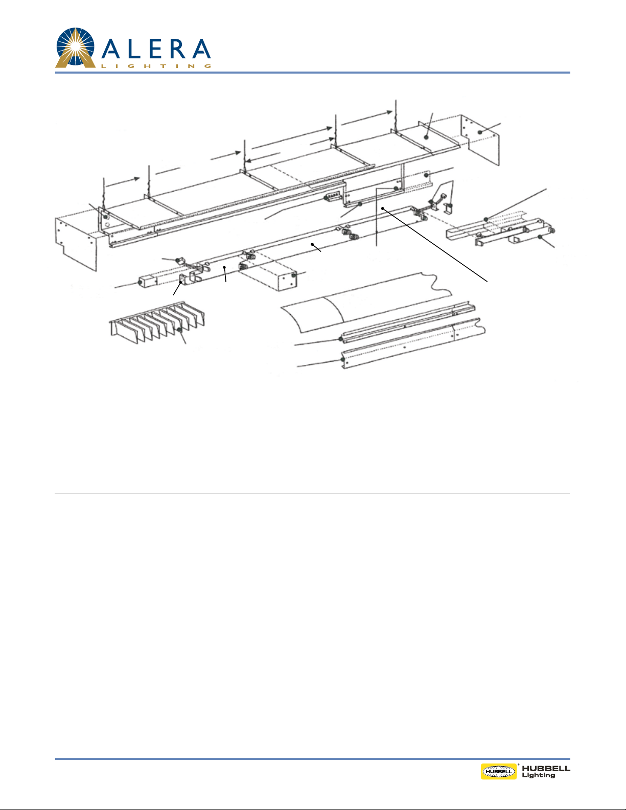
Straight Run (View shown from wall side)
Work in this direction
Power Feed
Endplate
Service Cover
Power Access Only
21" Housing
Plug-In Connector
Electrical End
Assembly
33" Housing
AL3-2T8-EPU
3' Electrical Unit
Parabolic Louver
Sample: AL-2T8-P-R-LD-EPU-15.00 consists of:
Trim Connector/
Aligner
Wall Rail
Wall Plate
(where required)
Hanging
Wires
90" Housing
Trim Rail,
cut to length
AL4-2T8-EPU
4' Electrical Unit
Connector Plate
Adjustment Housing
Drill (4) holes
(template provided)
Reector
(where required)
Adjustment
Cut
Electrical End
Assembly
Endplate
AL3-2T8-EPU-ADJ
3' Adjustable Electrical Unit
AL4-2T8-EPU
4' Electrical Unit
Wireway cover
(cut to length)
(3) 92745 Wall Rails
(3) 92746 Wall Plates
(1) 97561-00 90" Housing
(1) 97561-03 33" Housing
(1) 97561-04 21" Housing
(1) 97559-00 ADJ Housing
(2) AL4 2T8 EPU
(1) AL3 2T8 EPU
(1) AL3 2T8 EPU ADJ
(4) 107945-04 Parabolic Louvers
(1) 116612 Electrical End Assembly
(2) 97416-00 End Row End Plates
(4) 114084 Reector
General
1. Fasteners not provided for wall rail or wall plates.
2. All fasteners provided for housing, endplates, connector/aligners and electrical unit connections.
3. Pieces requiring a eld cut: Wall Rail (steel), Wall Plate (steel), Trim Rail (aluminum), Wireway Cover (aluminum) and Diusers (plastic,
steel, or aluminum)
Housing (CAUTION: For hard ceiling applications, see page 4.)
1. Install wall rails (see next page), fasteners not provided.
2. Install wall plates if required. Fasteners not provided.
3. Starting from right end of row (facing wall) install endplate on rst (shortest) housing with screws and nuts provided.
4. Install rst (shortest) housing and work to left installing progressively longer housings.
5. Top lip of housings tip into upper hook form of wall rail. Secure housing rmly in place by attening wall rail bend tab over housing lip.
6. Connect hanging wires loosely.
7. Install each successive housing (shortest to longest) in similar manner, connecting housings with screws and nuts provided and then hang
loosely on hanging wires.
8. Also install trim connector/aligners at each joint as row installation progresses.
9. Install endplate on adjustable housing into last "xed length" housing and hang entire assembly as a unit. Adjustable housing is then pulled
out to required dimension.
10. Square-cut trim rail for adjustable housing to required length; drill four (4) each 7⁄32" holes using template provided and install with sheet
metal screws.
11. Level entire row on hanging wires.
Page 1 /4 Rev. 01/14/ 14 RECESSED / AL 2-LIGHT TID
© 2014 Ale ra Lighting, a division of Hubbell Lighting, Inc. S pecifications su bject to change without notice.
701 Millennium Blvd. Greenville, SC 29607 / Tel 864.678.1000 / Website www.aleralighting.com
IN STA LL ATI ON DATA
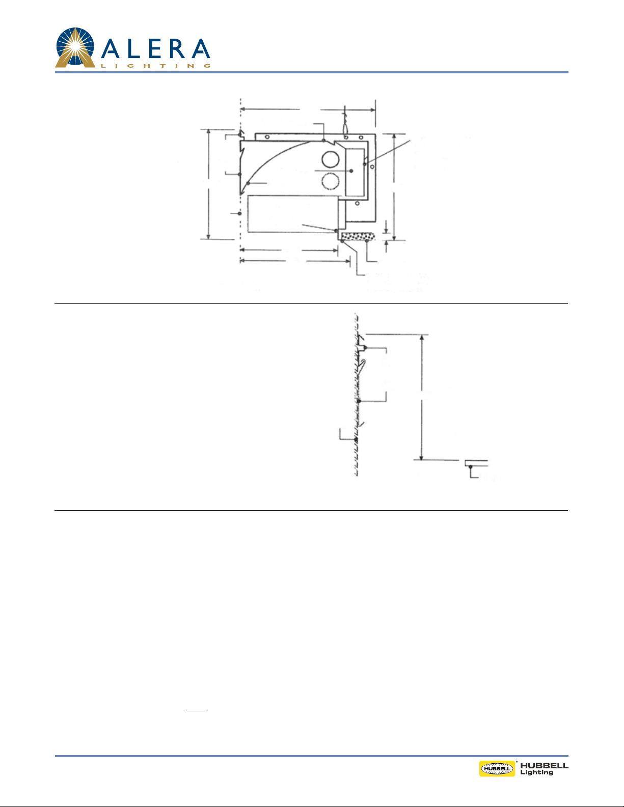
Step One - Install Wall Rail
Wall
Rail
Wall
Plate
10⅜"
Wall
AL-2T8P-R-LD
"AL" Housing (Chassis)
Electrical Unit
Reector
Parabolic Louver
Non-supporting
xture trim
8½"
15
⁄32"
9
AL 2-LIGHT
Technical Installation Data
12"
Access to ceiling for wiring and
J-box inspection must be cut in
housing by installing contractor
10"
1"
Ceiling Tile (by others)
Install drywall into xture
trim and secure other end to
building structure
1. Mount wall rail to wall 10⅜" from nished ceiling
plane to top of wall rail. Fasteners not provided. Wall rail
Wall Rail
furnished in 90" sections.
2. Where applicable, hook wall plate over bottom lip of
wall rail and fasten to wall.
Wall Plate
10⅜"
3. Install AL components per instructions.
4. Important: To save steps and time:
A. Start at the right end of each row facing the wall and
Wall
work left and
B. Install smallest (lower wattage) housings and electrical
units rst and then work up to the largest units.
Ceiling Plate
Electrical
1. Starting from right end of row (facing wall), snap in place electrical unit, starting with the shortest unit and progressing to the longest unit.
2. Each unit has polarized plug-in connector. After wire connections, secure units together with connector plate that slips over lampholders.
Screws are provided.
3. Power feed is at end of row. Clip o plug to make connections. Install service cover and electrical end assembly.
4. Determine length for snap-on wireway cover for adjustable unit. Cut wireway cover, plug in wiring connection and snap adjustable unit
into place.
5. Install clip to hold Adjustable Unit in place.
6. Install lamps.
7. Install lamp shield.
8. Where required, snap in reectors. Reectors overlap at adjustable unit.
Diusers
1. Install plastic shielding bae or parabolic louver. Cut last piece to t. Note: On parabolic louver, it may be necessary to cut the last
two (2) louvers to maintain an even louver spacing appearance.
2. Plastic or bae lays in place: parabolic louver cantilevers o lip trim rail.
3. Important: Cut nal plastic piece after sucient lamp or building warm-up to allow for plastic expansion.
Page 2 /4 Rev. 01/14/14 RECESSED / AL 2-LIGHT TID
© 2014 Ale ra Lighting, a division of Hubbell Lighting, Inc. S pecifications su bject to change without notice.
701 Millennium Blvd. Greenville, SC 29607 / Tel 864.678.1000 / Website www.aleralighting.com

IN STA LL ATI ON DATA
Pattern with Corners (View shown from wall side)
Work in this direction
Adjustable
Housing
Adjustable
Electrical Unit
Inside Corner Reector
Inside Corner Louver
Power Feed
Inside Corner
Housing
Inside Corner Flex
Trim Connector/
Aligner
Access Only
21" Housing
Electrical
Unit
90" Housing
Electrical Unit
Inside Corner ReectorService Cover Power
Adjustable
Housing
Trim Rail, Cut
to length
AL 2-LIGHT
Technical Installation Data
Outside Corner
Housing
Electrical
Adjustable Electrical Unit
Unit
21" Housing
Outside Corner Flex
Outside Corner Reectors (2)
Outside Corner Louver
Note: Wall Rail and Wall Plate not shown (see below)
Special Notes for Patterns with Corners
1. Housings: When installing patterns with corners, install corner housings rst after the installation of all wall rails (and wall plates). Then
proceed with each straight run per above.
2. Electrical: (a) AL row lengths are pre-calculated to provide ample light in corners. Be sure electrical units extend fully into corners before
eld cutting. (b) For corners requiring a continuous circuit around corner, a pre-cut ex conduit connector kit is provided
3. Diusers: Plastic for corners has pre-cut 45 angles. Install angled corner pieces rst and then straight-cut nal remaining piece to t.
Page 3 /4 Rev. 01/14/1 4 RECESSED / AL 2-LIGHT TID
© 2014 Ale ra Lighting, a division of Hubbell Lighting, Inc. S pecifications su bject to change without notice.
701 Millennium Blvd. Greenville, SC 29607 / Tel 864.678.1000 / Website www.aleralighting.com

Wall Rail
12"
"AL" Housing (Chassis)
AL 2-LIGHT
Technical Installation Data
Access to ceiling for
wiring and J-Box
inspection must be cut
in housing by installing
contractor
10 ⅜"
Wall Plate
Reector
Wall Line
Electrical Unit
Parabolic Louver
Non-supporting
xture trim
8 ½"
9 15⁄32"
10"
Ceiling Construction (by others)
Install drywall into xture
trim and secure other end to
building structure
HARD CEILING APPLICATIONS
The AL system is designed primarily for suspended acoustical ceilings. Fixture trim will not support drywall. Additional drywall support must be
provided adjacent to xture by ceiling installer.
The sketch to the right shows a method of installing the AL in a drywall ceiling. Note the ceiling must be installed after the AL housings. Also,
the access holes to the plenum through the xture must be cut by the contractor.
Page 4 /4 Rev. 01/14/ 14 RECESSED / AL 2-LIGHT TID
© 2014 Ale ra Lighting, a division of Hubbell Lighting, Inc. S pecifications su bject to change without notice.
701 Millennium Blvd. Greenville, SC 29607 / Tel 864.678.1000 / Website www.aleralighting.com
 Loading...