

Page 1
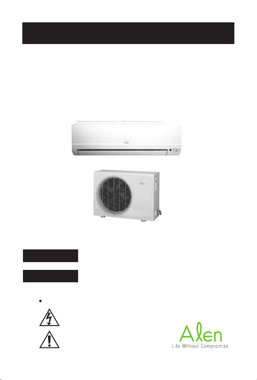
INSTALLATION MANUAL
SPLIT TYPE ROOM AIR CONDITIONER
MODEL: AMS09 9000 BTU and 14.5 SEER
AMS12 12000 BTU and 13.5 SEER
WARNING
CAUTION
Electrical Hazard Symbols
ELECTRICAL
SAFETY / ALERT
This symbol refers to hazard or unsafe practices which can
result in severe personal injury or death
This symbol refers to hazards or unsafe practices which can
result in severe personal injury or death and the potential for
product or property damage.
Page 2

CONTENTS
Important
Special Precautions
Installation Manual
Installation Precautions
EVAPORATOR (INDOOR) UNIT INSTALLATION
1) Mounting and Installation Plate
2) Connective Pipe and Drainage Installation
3) Indoor Unit Installation
4) Wiring
5) Connecting Cables
CONDENSOR (OUTDOOR) UNIT INSTALLTION
1) Outdoor Installation Precautions
2) Drain Elbow Installation
3) Refrigerant Piping Connection
4) Wiring Connection
AIR PURGE TEST
1) Air Purge
2) Gas Leak Check
3) Test Operation
For warranty inFormation, please reFer to
www.alencorp.com
1
Page 3

IMPORTANT!
Please Read Before Starting
This air conditioning system meets strict safety and operating standards. As
the installer or service person, it is an important part of your job to install or
service the system so it operates safely and efficiently.
For safe installation and trouble-free operation, you must:
• Carefully read this instruction booklet before beginning.
• Follow each installation or repair step exactly as shown.
• Observe all local, state, and national electrical codes.
• Pay close attention to all danger, warning, and caution notices
given in this manual.
Have it installed by a certied professional
Always use a certified HVAC professional to install the split air conditioning
system to prevent damage to the unit or injury to yourself. The vacuuming
and charging of the line set is required during installation. Improper instal-
lation can result in water or refrigerant leakage, electrical shock, or fire. Be
sure to check with your local codes as an electrician may be needed to install
a dedicated power circuit.
In Case of Improper Installation
The manufacturer shall in no way be responsible for improper installation
or maintenance service, including failure to follow the instructions in
this document.
2
Page 4

SPECIAL PRECAUTIONS
When Wiring
ELECTRICAL SHOCK CAN CAUSE SEVERE
PERSONAL INJURY OR DEATH. ONLY A
QUALIFIED, EXPERIENCED ELECTRICIAN
SHOULD ATTEMPT TO WIRE THIS SYSTEM.
• Do not supply power to the unit until all wiring and tubing are
completed or reconnected and checked.
• Highly dangerous electrical voltages are used in this system.
Carefully refer to the wiring diagram and these instructions
when wiring. Improper connections and inadequate grounding can
cause accidental injury or death.
• Ground the unit following local electrical codes.
• Connect all wiring tightly. Loose wiring may cause overheating
at connection points and a possible fire hazard.
When Installing...
...In a Ceiling or Wall
Make sure the ceiling/wall is strong enough to hold the unit’s weight. It may
be necessary to construct a strong wood or metal frame to provide added
support.
...In a Room
Properly insulate any tubing run inside a room to prevent “sweating” that can
cause dripping and water damage to walls and floors.
...In Moist or Uneven Locations
Use a raised concrete pad or concrete blocks to provide a solid,
level foundation for the outdoor unit. This prevents water damage
and abnormal vibration.
...In an Area with High Winds
Securely anchor the outdoor unit down with bolts and a metal frame. Provide
a suitable air baffle.
3
Page 5

SPECIAL PRECAUTIONS
When Connecting Refrigerant Tubing
• Keep all tubing runs as short as possible.
• Use the flare method for connecting tubing.
• Apply refrigerant lubricant to the matching surfaces of the
flare and union tubes before connecting them, then tighten
the nut with a torque wrench for a leak-free connection.
• Check carefully for leaks before starting the test run.
When Servicing
Turn the power OFF at the main circuit breaker panel before opening the unit
to check or repair electrical parts and wiring. Keep your fingers and clothing
away from any moving parts. Clean up the site after you finish, remembering
to check that no metal scraps or bits of wiring have been left inside the unit
being serviced. After installation, explain correct operation to the customer,
using the operating manual.
This air conditioner uses R410A.
Please make note of these differences
(1) Since the working pressure is 1.6 times higher than that of conventional
refrigerant(R22) models, some of the piping and installation and service
tools may be different.
(2) Models that use refrigerant R410A have a different charging port thread
diameter to prevent erroneous charging with conventional refrigerant(R22)
and for safety. Therefore, check beforehand. [The charging port thread
diameter for R410A is 1/2 threads per inch.]
(3) Be careful that foreign matter (oil, water, etc.) does not enter the piping. Also, when storing the piping, securely seal the opening by pinching,
taping, etc...
(4) When charging the refrigerant, take into account the slight change in
the composition of the gas and liquid phases, and always charge from the
liquid phase side whose composition is stable.
4
Page 6

INSTALLATION MANUAL
For Room Air Conditioner
(Split Wall-Mounted Type)
Parts Installation
Part
Name of part Qty
#
1 Installation Plate 1
2 Mounting Screw ST3.9 x
25-C-H
3 Clip Anchor 8
4
Refrigerant
Pipe
Liquid Side
Gas
Side
<12000 Btu/h
>12000Btu/h
O 1/4”
O 3/8”
O 1/2”
5 Remote Controller 1
6 Seal 1
7 Drain Elbow 1
Anchor Bolts for Condensor Installation
* The condensor unit should not be
exposed to strong wind.
* Fix the condensor unit with O 3/8”
anchor bolts.
A
AIR INLET
BOLTS
8
BOLTS
MODEL A (inches) B (inches)
<12000Btu/h 215 105
>12000Btu/h 208 114
5
B
BOLTS
BOLTS
AIR OUTLET
Page 7

INSTALLATION PRECAUTIONS
Selecting the Location for the Indoor and Outdoor Units:
The following should be reviewed prior to selecting the location for your installation.
Evaporator Unit (Indoor Unit)
Install the indoor unit level on a wall that can support the weight of the unit and
is not subject to vibration.
The inlet and outlet ports should not be blocked.
Install the unit near an electric outlet or special branch circuit.
Do not install the unit where it will be exposed to direct sunlight.
Install the unit where connection to the outdoor unit is easy.
Install the unit where the drain pipe can be easily installed.
Install in a location where the unit can be easily accessed for maintenance.
Ensure there is a clearance of at least 6 inches above and 5 inches on either
side of the unit.
Condensor Unit (Outdoor Unit)
If possible, do not install the unit where it will be exposed to direct sunlight. (If
necessary, install a blind that does not interfere with the air flow.)
Do not install the unit where a strong wind blows or where it is very dusty.
Do not install the unit where people can come into contact with the unit.
Install in an area where the noise from this unit will not disturb your neighbors.
Ensure there is a clearance of the following minimum distances from the unit:
Above: 24 inches
In front: 24 inches
Behind: 12 inches
Side with connections: 24 inches
Side without connections: 4 inches
Notes on the remote control installation
• Keep the remote at least one yard from a TV or radio.
• Do not place in an area that is exposed to direct sunlight or a heat source
• Ensure batteries are inserted properly
6
Page 8

CAUTION
1.
2.
3.
4.
5.
Connect the (evaporator) indoor unit
rst then the outdoor unit and bend
and arrange the pipe carefully.
Ensure there is no slack in the drain
hose.
After removing drain hose,
be sure not to forget mounting
drain cap.
Be sure to x the drain hose with
tape to the bottom of piping.
Prevent drain water from freezing in
low temperature environments. When
installing evaporator (indoor) unit’s
drain hose outdoors, necessary measures for frost protection should be
taken to prevent the drain hose from
freezing(becoming blocked) which
could result in water leakage.
6.
Measures for frost protection should
be taken to prevent the drain hose
from freezing (becoming blocked)
which could result in water leakage.
7
Page 9
EVAPORATOR INSTALLATION (INDOOR)
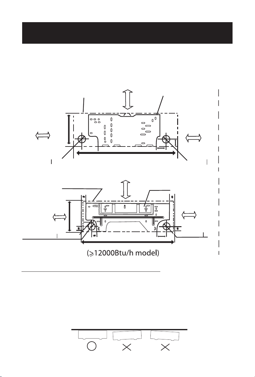
Evaporator (Indoor) Unit Outline
6” inches or more to ceiling
Installation Plate
4.7 inches or more
to the wall
4.7 inches or more
to the wall
11”
Left refrigerant
pipe hole O 2.56”
1.97”
1.97”
32.09”
Right refrigerant
pipe hole O 2.56”
(<12000Btu/h model)
Evaporator (Indoor) Unit Outline
6 inches or more to ceiling
Installation Plate
4.72 inches or more
to the wall
4.72 inches or more
to the wall
11.42”
Left refrigerant
pipe hole O 2.56”
1.97”
3.54”
35.67”
Right refrigerant
pipe hole O 2.56
1.93”
1.97”
2.17”
1.65”
The Installation Plate would look like one of the
following (Depending on the models):
Installation plate and its dimensions (Unit: Inches)
1) Mounting Installation Plate
i) Fix the installation plate
1) Install the installation plate horizontally on structural parts in the walls with the spaces
provided around the plate.
2) In case of brick, concrete or similar type of walls, Make holes in the wall. Insert clip anchors
for appropriate mounting screws.
3) Fix the installation plate on the wall.
Installation Plate
8
Page 10
EVAPORATOR INSTALLATION (INDOOR)
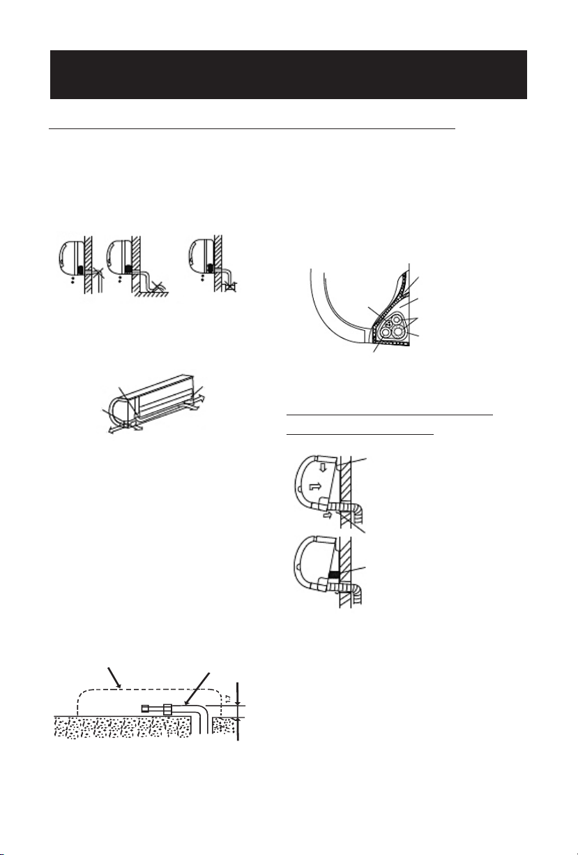
2) Connective Pipe and Drainage Installation
i) Drainage
Run the drain hose downward.
Do not install the drain hose as illustrated below.
Do not form a rise
Do not put the hose
end into water
ii) Connective Pipe
Pipe holder
Pipe cover
Right piping Right back piping
a) For the left-hand and right-hand piping,
remove the pipe cover from the side panel.
Explain to the customer that the pipe cover
must be kept as it may be used if the air
conditioner is moved to another location.
b) For the left-hand and rear-left-hand piping, install the piping as shown. Bend the
connective pipe to be
placed at a height of 1 5/8 inches
or less from the wall.
Evaporator (Indoor) Unit outline
c) Fix the end of the connective pipe.
(Refer to Tightening Connection in
Refrigerant Piping Connection).
Pipe Cover
Left piping
Left back piping
Connective Pipe
“
iii) Piping and Bandaging
Wind the Connective cable, drain hose
and wiring tape securely, evenly as
shown below.
Evaporator (Indoor) Unit
Ponding Box
Connective Cable
Drain Hose
Pipe Room
Connective Pipe
Wrapping Belt
3) Evaporator (Indoor)
Unit Installation
i) Pass the piping through
the hole in the wall
ii) Put the upper claw at
the back of the installation
plate, move the evaporator
(indoor) unit from side to
side to see if it is securely
hooked.
iii) Insert a spacer between the evaporator
(indoor) unit and the wall bracket to separate the bottom of the unit from the wall.
iv) Push the lower part of the evaporator
(indoor) unit up on the wall. Then move
the evaporator (indoor) unit from side to
side, up and down to check if it is hooked
securely.
9
Page 11
EVAPORATOR INSTALLATION (INDOOR)
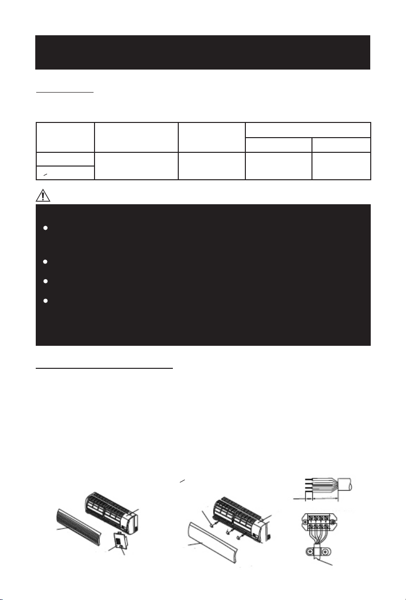
4) Wiring
Prepare the power source for exclusive use with the air conditioner.
The supply voltage must comply with the rated voltage of the air conditioner.
Model Power Source
<12000Btu/h
>12000Btu/h
60 Hz 115V~ 32/25A 14 18
Plug socket and
fuse rating
Power Supply Cord Connecting Cable
CAUTION
Perform the wiring with sufficient capacity. Installation legally requires a
short circuit isolator to be attached to prevent electrical shock.
Do not extend the power cable cord by cutting.
Power voltage should be in the range of 90% ~110% of rated voltage.
The plug of the air conditioner takes a grounding leg, so clients should
use a grounding socket so that the air conditioner can be
grounded efficiently.
AWG (MIN)
5) Connecting Cables
i) Evaporator (Indoor) and Condensor (Outdoor) connecting cable should be Aw18 or more.
ii) Remove the panel and screw, then remove the window cover (for <12000Btu/h models).
Remove the panel screws covers , then remove the screws and take out the frame
(for model >12000Btu/h models)
iii) Connect cables according to their marks to terminals.
iv) Wrap those cables not connected with terminals with insulation tapes, so that they will not touch any electrical components.
< 12000Btu/h models
Panel
Window Cover
Screw
Frame
> 12000Btu/h models
Screw Cover
Panel
10
Frame
Code Wire
0.4”
1.6”
Terminal block of indoor unit
To outdoor
unit
Page 12
CONDENSOR INSTALLATION (OUTDOOR)
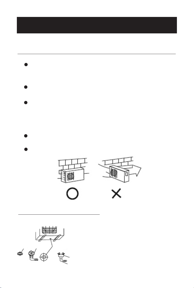
1) Condensor (Outdoor) Unit Installation Precaution
Install the outdoor unit on a rigid base to prevent increasing noise level and
vibration. Determine the air outlet direction where the discharged air is not
blocked.
In the case that the installation place is exposed to strong wind place the
unit lengthwise along the wall or use dust or shield plates.
If need suspended installation, the installation bracket should accord with
technique requirement in the installation bracket diagram. The connection
between bracket and wall, bracket and the air conditioner should be firm,
stable and reliable.
Be sure there is no obstacle which blocks the air flow.
Install the unit on a flat, level surface where is can be fastened securely.
Strong wind
2) Drain Elbow Installation
Fit the seal into the drain elbow, then insert
the drain elbow into the base pan hole of the
condensor (outdoor) unit, rotate 90o to securely
assemble. Connect the drain elbow with an
extension drain hose (locally purchased), in case
Seal
the water drains off the condensor (outdoor) unit
during the heating mode. (heating models only).
11
Seal
Drain Elbow
Base pan hole of
condensor
(outdoor) unit
Drain Pipe
Page 13
CONDENSOR INSTALLATION (OUTDOOR)
3) Refrigerant Piping Connection
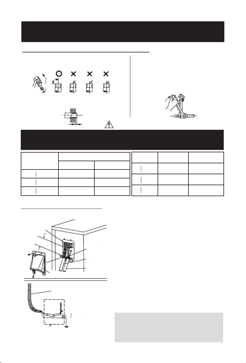
i) Flaring
Cut a pipe with a pipe cutter
Insert a flare nut into a pipe and flare the pipe
CAUTION
ii) Tightening Connection
Align pipes to be connected.
Sufficiently tighten the flare nut with
fingers, and then tighten it with a
spanner and torque wrench as shown.
Excessive torque can break the flare nut and cause a leakage of refrigerant.
* Ensure the refrigerant pipe is firmly attached before running the compressor.
Outer Diameter (inches)
A (inches)
Max. Min.
O 1/4 0.5 0.028
O 3/8 0.6 0.04
O 1/2 0.7 0.04
Outer Diameter
O 1/4
O 3/8
O 1/2
Tightening Torque
(N. inches)
11.57 ft lbs
(160kgf.cm)
21.7 ft lbs
(300kgf.cm)
36.14 ft lbs
(500kgf.cm)
4) Wiring Connection
Condensor (Outdoor) Unit
Terminal block
Over 1.7”
Cover Control
Conduit panel
Connecting
cable
Power
supply
cord
i) Remove the cover control from the unit by
loosening 3 screws.
ii) Dismount caps on the conduit panel.
iii) Temporarily mount the conduit tubes
(not included) on the conduit panel.
iv) Properly connect both the power supply
and low voltage lines to the corresponding
terminals on the terminal block.
v) Ground the unit in accordance with local
codes.
vi) Be sure to size each wire allowing several
Power supply cord
inches longer than the required length for
wiring.
vii) Use lock nuts to secure the conduit tubes.
Power supply
115V - 60Hz
Note: To prevent wires from loosening or leaving the Cord Clamp, please
select proper cord diameter to fill the
Special Branch Circuit Breaker
(Fuse/Breaker capacity: 20A)
holes on the cord clamp
12
Additional Tightening
torque (N. inches)
14.45 ft lbs
200kgf.cm)
25.30 ft lbs
(350kgf.cm)
39.75 ft lbs
(550kgf.cm)
Page 14
AIR PURGE AND TEST OPERATION
1) Air Purge
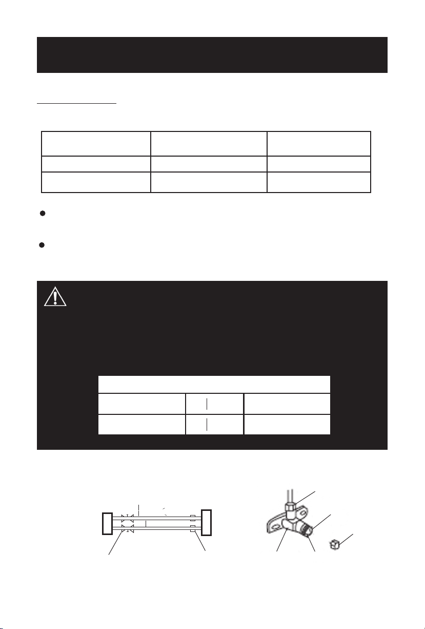
Choose Purge method from the table.
Connective Pipe Length Air Purging Method
less than 16.4 feet
16.4 ~ 32.8 feet
Use vacuum pump
Use vacuum pump
Additional amount of
refrigerant to be charged
N/A
0.32 ounces per foot for each foot
beyond 16.4 feet (5 meters).
Make sure the R410A refrigerant added into air conditioner is liquid form.
When relocating the unit to another place, perform evacuation, with a
vacuum pump.
CAUTION IN HANDLING THE PACKED VALVE
Open the valve stem until it hits against the stopper. Do not try to open it further.
Securely tighten the valve stem cap with a spanner or the like.
Valve stem cap tightening torque.
Liquid pipe side O 1/4”
Gas pipe side O 3/8”
11.57 ft lbs
(160kgf.cm
21.7 ft lbs
(300kgf.cm)
condensor
(outdoor)
unit
Packed Valve
Refrigerant Gas
evaporator
(indoor) unit
O 0.5 inches (>10000Btu/h)
A
O 0.38 inches (<9000Btu/h)
O 0.25 inches
B
C
D
Half union
13
Packed valve
Flare nut
Stopper
Cap
Valve stem
Page 15
AIR PURGE AND TEST OPERATION
When Using The Vacuum Pump
(For method using a manifold valve, refer to this operation manual.)
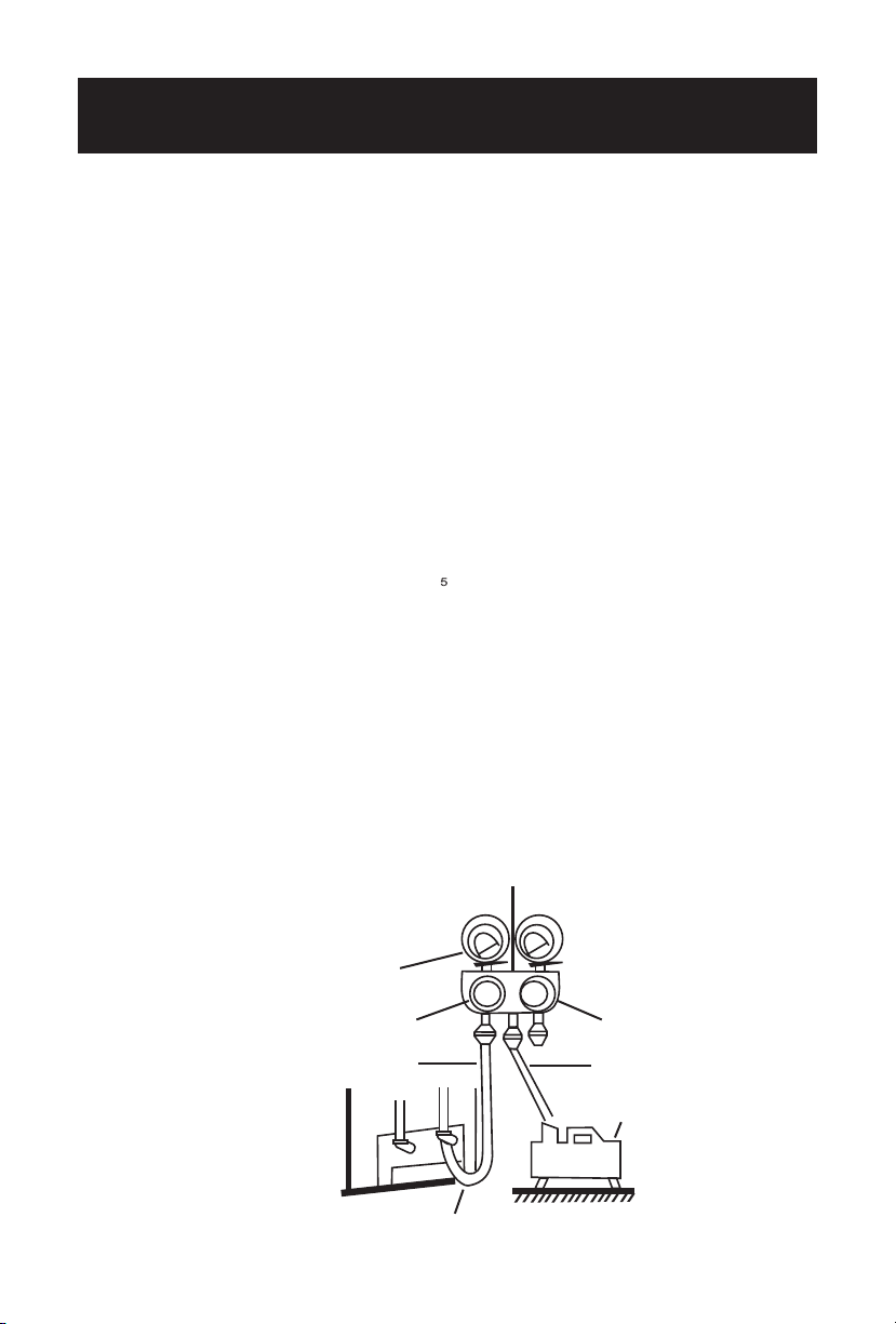
i.
Completely tighten the flare nuts, A, B, C, D, connect the manifold valve
charge hose to a charge port of low-pressure valve on the gas pipe side.
ii.
Connect the charged hose connection to the vacuum pump.
iii.
Fully open the handle “Lo” of the manifold valve.
iv.
Operate the vacuum pump to evacuate. After starting the evacuation,
slightly loosen the flare nut of the “Lo” valve on the gas pipe side and
check that the air is entering. (Operation noise of the vacuum pump
changes and a compound meter indicated 0 instead of minus)
v.
After the evacuation is complete, fully loosen the handle “Lo” of the
manifold valve and stop the operation of the vacuum pump.
Make evacuation for 15 minutes or more and check that the compound
meter indicates -76cmHg(-1.0x10 Pa).
vi.
Turn the stem of the packed valve B about 45o counter clockwise for 6~7
seconds after the gas comes out, then tighten the flare nut again. Make
sure the pressure display in the pressure indicator is a little higher than
the atmosphere pressure.
vii.
Remove the charge hose from the Low pressure charge hose.
viii.
Fully open the packed valve stems B and A.
ix.
Securely tighten the cap of the packed valve.
Manifold Valve
Compound meter
-76cmHg
Handle “LO”
Charge hose
Pressure gauge
Handle “HI”
Charge hose
Vacuum pump
Low pressure valve
14
Page 16
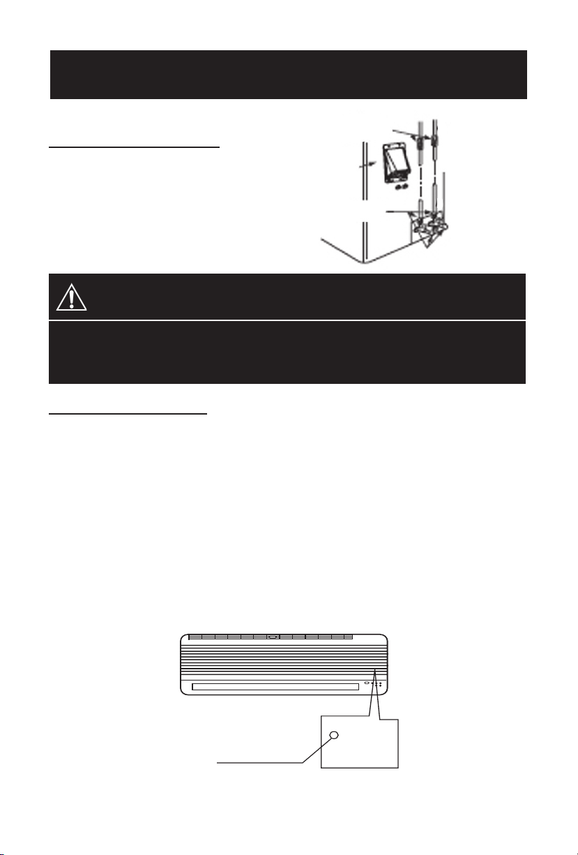
AIR PURGE AND TEST OPERATION
Evaporator (indoor)
2. Gas Leak Check
unit check point
Make sure no gas comes out
from the connections with a
Evaporator (indoor)
unit check point
B
leak detector or soap water.
CAUTION
A: Lo packed valve B: Hi packed valve
C and D: end of Evaporator (indoor) unit connection.
3. Test Operation
Perform test operation after completing gas leak check and installation.
Connect the power. Push the “COOL” button on the control panel to
i.
begin testing.
Check if all the functions work well while testing the air conditioner.
ii.
A protection feature prevents the air from being activated for about 3
minutes when it is restarted immediately after operation or when the
power switch is switch on.
CD
A
Push the “COOL” button again till the running light switch off after
iii..
finishing the test operation.
MANUAL BUTTON
AUTO / COOL
15
 Loading...