

Page 1
8553
p
p
(
)
Service Guide
Medium-Pressure Lubricant Pump
Description
The major components of the medium-pressure
lubricant pump assembly in the 8553 model series consist
of a(n):
• air-operated motor
• double-acting reciprocating pump tube
• control valve assembly, z-swivel, and delivery hose
• cover w/ or w/o handle assembly (model dependent)
These medium-pressure pumps are designed to
deliver:
• light through medium-viscosity non-fibrous
lubricants
• rust-proofing compounds
8553-1 8553-2
8553-A 8553-B
Models 8553, 8553-1, 8553-2, 8553-A, and 8553-B
All pump models are obsolete except for model
8553-2. Service parts are available for all models.
Specifications
Air Motor
Piston Diameter / Stroke
Inches mm psi Bars
2-7/16 x 1-5/8 62 x 41 1/4 " NPSI (f) 200 14
For air motor data, refer to Service Guide SER 324300-5
Air Inlet
Pump Tube
Max. Material
Material
Outlet
3/8 " NPTF (f) 5200 359 0.75 2.8 0.47 7.7
* For detailed information, refer to SER 331571-A5
Pressure
psi Bars gal l ci cc
Delivery/Minute
(Approximate)*
Max. Air Pressure
Displacement/
Cycle
Pump
Model
8553
8553-2 338166 331571-C5
8553-A
8553-B
Cover
330658-4
338371
318040-4
Original
Stripped
Pump
Model
331571-F1
Current
Stripped
Pump
Model
331571-C5
331571-A5 120 50 16 331571-B5 400 180 55 200/20 5
Container Size
lbs kg gal l
35 - 5 -8553-1 331571-F2
Ta ble 1 Pump Model 8553 Series Specifications
397599 and is not to be co
This document contai ns conf identi al infor mation that is the proper ty of Alemit e Corpora tion
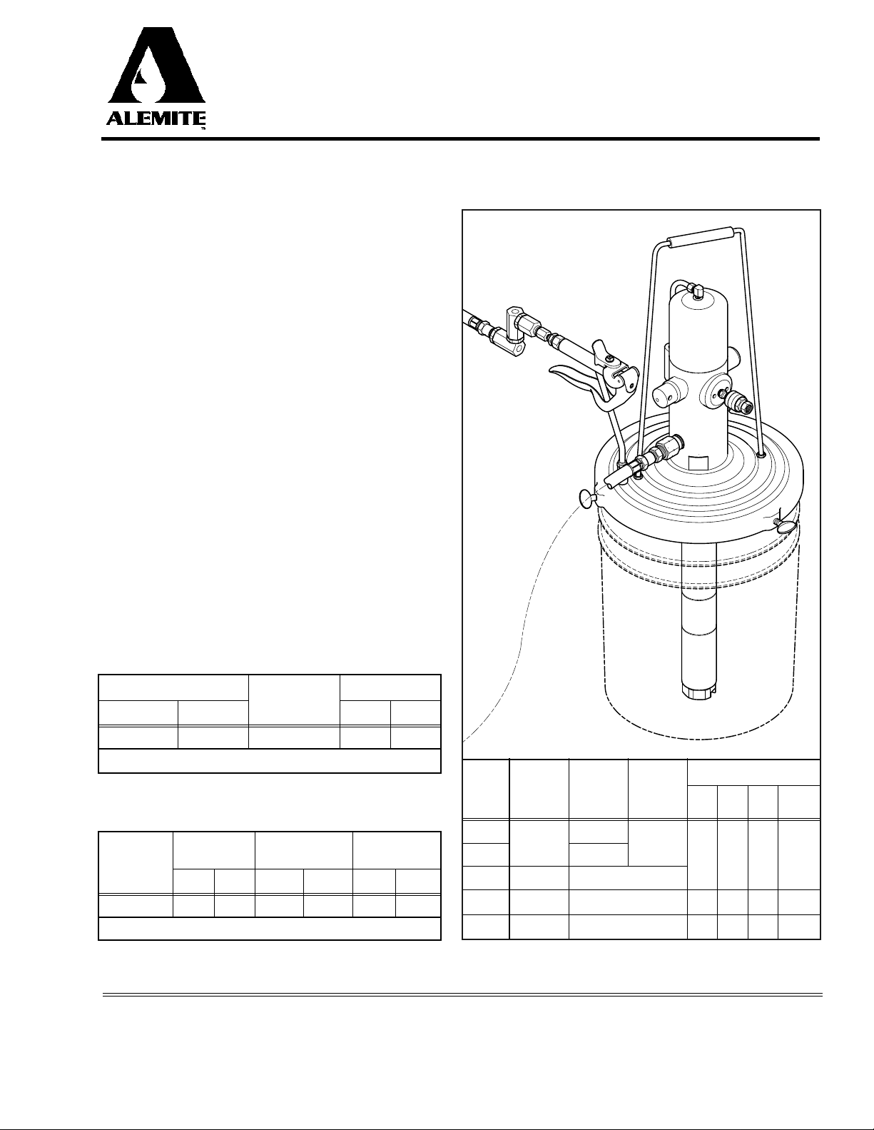
Figure 1 Medium-Pressure Pump Model 8553 Series
Current Pump Model 8553-2 Shown
Alemite Corporation
PO Box 473515, Charlotte, North Carolina 28247-3515
www.alemite.com
Copyright © 1998 by Alemite Co rporatio n
ied, used, or disclo sed to others with out express written
ermission. Revision
SER 8553
4-98
Page 2
SER 8553 Medium-Pressure Lubricant Pump
20
11
12
15
Apply
Loctite 222
Here
10
9
19
1
Apply
Thread Sealant
Here
Weep Hole
Apply
Thread Sealant
Here
2
3
A
18
5
4
To Item
Number 7
5
Apply
Thread Sealant
Here
14
6
17
7
19
Drain
8
Hole
8
Drain
Hole
16
A
Obsolete
Cover Assembly
13
A
Current
Cover Assembly
13
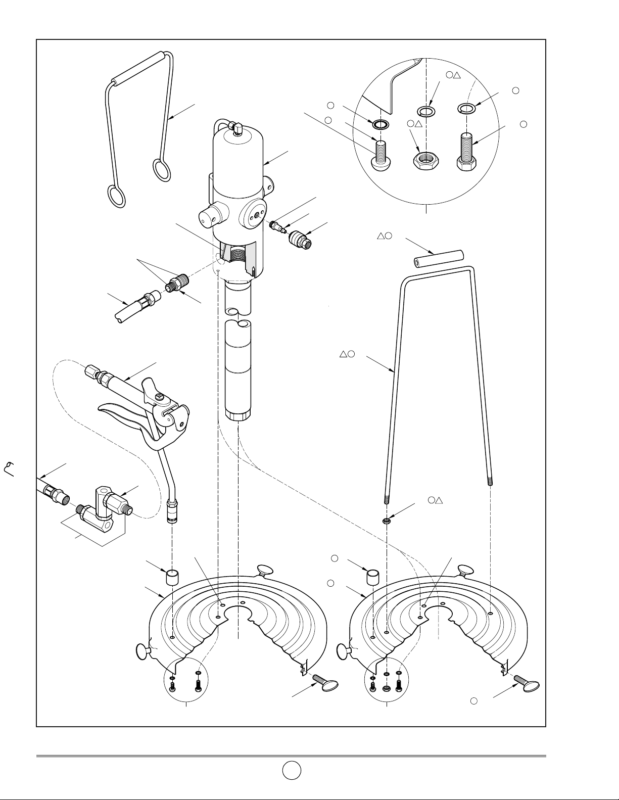
Figure 2-A Medium-Pressure Lubricant Pump Models 8553, 8553-1, and 8553-2 - Exploded View
Revision (4-98) 2 Alemite Corporation
Page 3
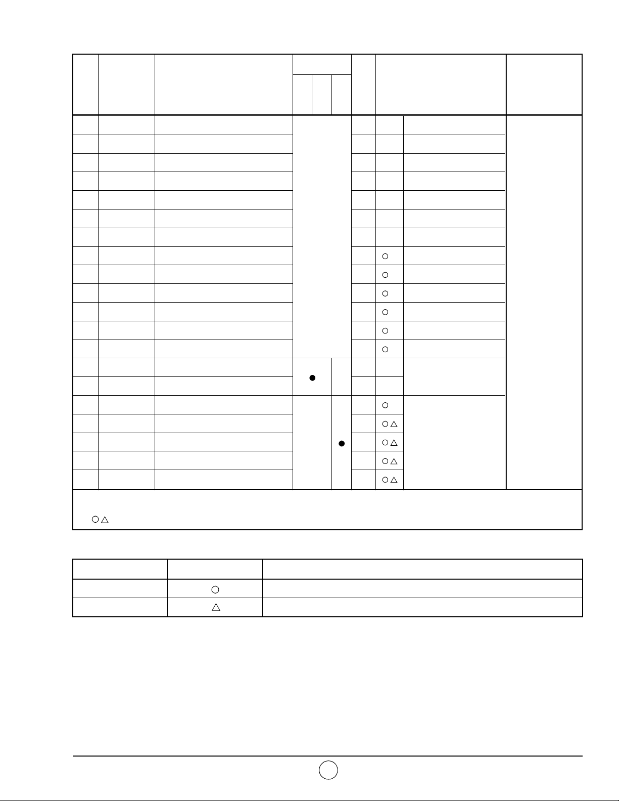
Medium-Pres sure Lubr icant Pu mp SER 8553
Model
Item
No.
Part No. Description
8553
Qty Notes
8553-1
8553-2
Numeric Order
Part # (Item #)
1 331571-C5 Pump Assembly
1 See SER 331571-A5 6320-3 (6)
2 328034 Connector, 1/4 " NPTF (m) 1 18223 (13)
3 328030 Coupler Air, 1/4 " NPTF (f) 1 44734 (4)
4 44734 Adapter, 3/8 " NPTF (m) 1 B52752 (7)
5 317875-25 Hose Assembly, Material 1
77009 (9)
6 6320-3 Valve Assembly 1 See SER 6320-3 77786 (12)
7 B52752 Z-Swivel Assembly 1 See SER B52750
All
8 315943 Bushing 1
79029 (19)
170561 (10)
9 Washer, Lock, 1/4 " 1 172207-1 (11)
10 Screw, 1/4 " -20 x 5/16 " 1
172207-2 (20)
11 172207-1 Washer, Lock, 1/4 " 3 315943 (8)
12 77786 Capscrew, 1/4 " -20 x 1/2 " 3 317875-25 (5)
13 18223 Screw, Thumb, 1/4 " -20 3
14 Cover Assembly 1
321678 (18)
321696 (17)
Obsolete
15 Handle Assembly 1 327137 (15)
16 Cover Assembly 1
328030 (3)
17 Handle 1 328034 (2)
18 Grip (Rubber) 1
Current
330657-B4 (14)
19 Nut, 5/16 " -18 4 331571-C5 (1)
20 Washer, Lock, 5/16 " 2
Legend:
Part numbers left blank (or in itali cs) are not available separately
designates a repair ki t item
338141 (16)
Repair Kits
Part No. Kit Symbol Description
338166 Kit, Cover
393607 Kit, Handle
Alemite Corporation 3 Revision (4-98)
Page 4
SER 8553 Medium-Pressure Lubricant Pump
1
Apply
Thread Sealant
Here
6
Weep Hole
Apply
Thread Sealant
Here
2
3
5
To Item
Number 7
To Item
Number 4
Thread Sealant
7
5
✪
9
Apply
Here
Drain
Hole
✪
10
4
✪
11
✪
12
A
13
A
✪
8
14
8
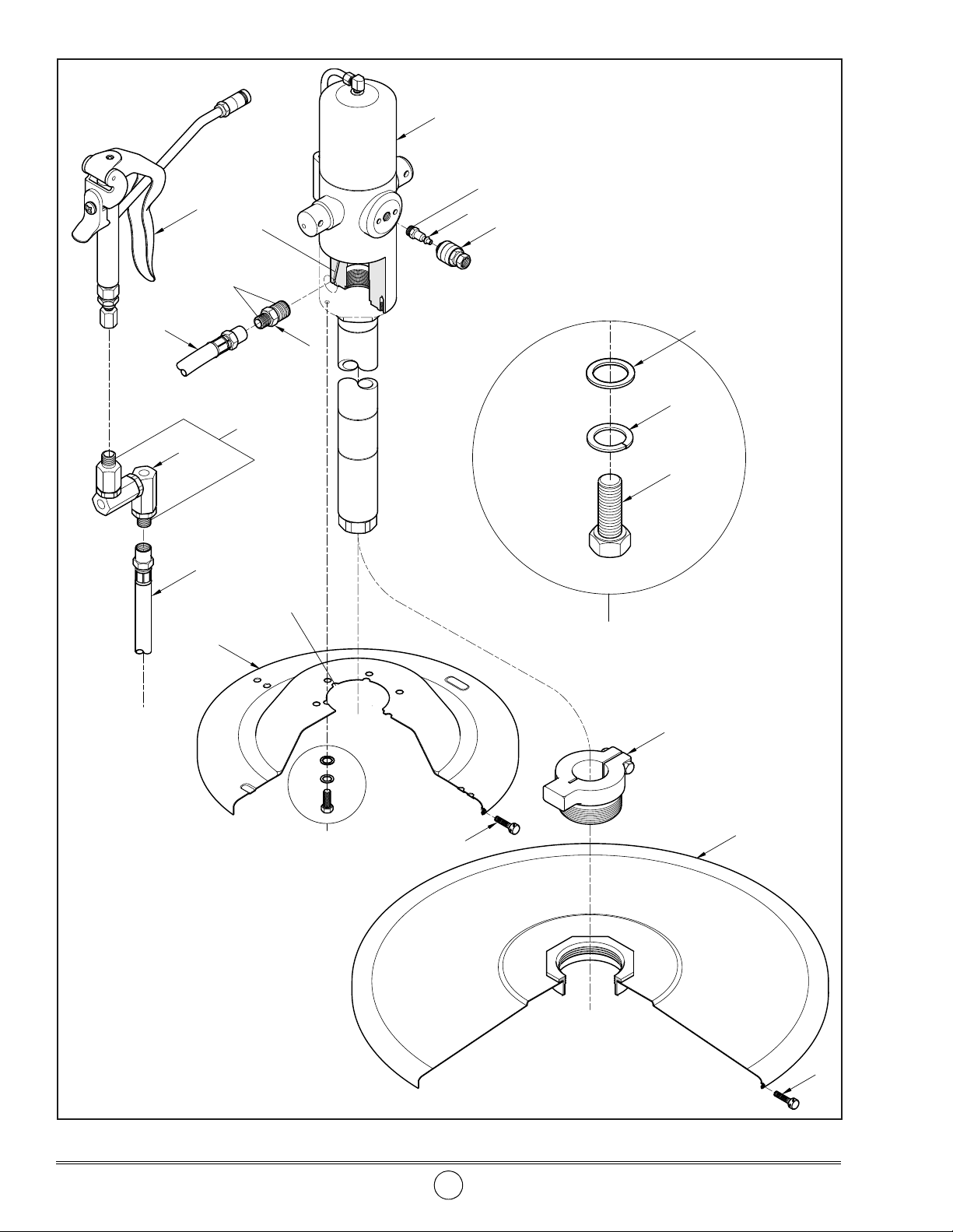
Figure 2-B Medium-Pressure Lubricant Pump Models 8553-A and 8553-B - Exploded View
Revision (4-98) 4 Alemite Corporation
Page 5
Medium-Pres sure Lubr icant Pu mp SER 8553
Model
Item
No.
Part No. Description
8553-A
Qty Notes
8553-B
Numeric Order
Part # (Item #)
1 331571-A5 Pump Assembly 1
6320-3 (6)
See SER 331571-A5
331571-B5 Pump Assembly 1
2 328034 Connector, 1/4 " NPTF (m)
3 328030 Coupler Air, 1/4 " NPTF (f) 1
1 44734 (4)
17804 (10)
48018 (8)
4 44734 Adapter, 3/8 " NPTF (m) 1 B52752 (7)
5 317875-25 Hose Assembly, Material 1
6 6320-3 Valve Assembly 1 See SER 6320-3
Both
77786 (12)
172207-1 (11)
7 B52752 Z-Swivel Assembly 1 See SER B52750 317875-25 (5)
8 48018 Screw, Thumb, 1/4 " -20 3
9 Cover Assembly 1
10 Washer, 1/4 " 3
11 Washer, Lock, 1/4 " 3
12 Capscrew, 1/4 " -20 x 1/2 " 3
13
326750 Adapter, Bung, 2 " NPTF (m) 1 331571-A5 (1)
✪
✪
✪
✪
✪
14 318040-4 Cover Assembly 1
Legend:
Part numbers left blank (or in itali cs) are not available separately
✪ designates a repai r kit item
318040-4 (14)
320998-B4 (9)
326750 (13)
328030 (3)
328034 (2)
331571-B5 (1)
Repair Kit
Part No. Kit Symbol Description
338371 ✪ Kit, Cover
Assembly
NOTE: The Pump Assembly bolts to the
NOTE: Refer to Figures 2 and 2-A for com-
ponent identification on all assembly procedures.
CAUTION
Select a clean environment for all assembly procedures. Prevent contamination from foreign material. Damage t o comp onents can occur.
Pump and Cover Assembly
IMPORTANT: Make sure to remove the protective sleeve from the inlet of Pum p Assembly (1).
1. Install Pump Assembly (1) i nto Cover (16).
2. Secure the Pump Assembly to the Cover with Lock
3. Install Grip (18) onto Handle (17).
4. Screw Nut (19) onto each end of the Handle.
5. Install the ends of the Handle into the Cover.
Cover with the weep hole in the air motor
aligned with the drain hole in the Cover.
See Figure 2-A.
Washers (11) and Capscrews (12).
• Tighten the Capscrews securely.
Model 8553-2
Alemite Corporation 5 Revision (4-98)
Page 6

SER 8553 Medium-Pressure Lubricant Pump
6. Install Lock Washer (20) and additional Nut (19) onto
each end of the Handle.
• Tighten the Nuts securely.
7. Fit the bolted Pump and Cover Assembly onto the
container.
8. Secure the Cover to the container with Thumb
Screws (13).
Model 8553-A
9. Install Pump Assembly (1) i nto Cover (9).
• Make sure the weep hole in the air motor is aligned
with the drain hole in the Cover. See Figure 2-B.
10. Secure the Pump to the Cover with Washers (10), Lock
Washers (11) and Capscrews (12).
• Tighten the Capscrews securely.
11. Fit the bolted Pump and Cover Assembly onto the
container.
12. Secure the Cover to the container with Thumb
Screws (8).
Model 8553-B
13. Screw Bung Adapter (13 ) into C over (14).
14. Install Pump Assembly (1) into the Bung Adapter.
• Make sure the pump is approximately 1/4-inch
(7 mm) from the bottom of the drum.
All Models
Air Inlet
16. Screw Connector (2) [with thread sealant] into the inl et o f the
air motor.
• Tighten the Connector se curely.
17. Attach Air Coupler (3) to an air line.
• Make sure the press ure rating of the air l ine is su fficient for
the pump.
18. Attach the Air Coupler Assembly to the Connector.
Control Valve and Material Hose
19. Screw t he la rge diameter end of Adapter ( 4) [with thread
sealant] into the ou tle t of th e Pu mp As se mbl y.
• Tighten securely.
20. Screw either end of Material Hose (5) [with thread sealant] into
the Adapter.
• Tighten securely.
21. Screw the 1/2 " -27 end of Z-Swivel (6) [with thread sealant]
into the Material Hose .
• Tighten securely.
22. Screw the opposite end of the Z-Swivel [with thread sealant]
into Control Valve Assembly (6).
• Tighten securely.
23. Test/Prime the Pump assembly.
15. Tighten the Bung Adapter securely.
Changes Since Last Printing
Added Model 8553-2
Revision (4-98) 6 Alemite Corporation
 Loading...