

Alemite 8424 Service Manual

Service Guide
Flow Meter
Description
General
This Electronic digital meter features a turbine
measurement system, designed for precise
measuring of low viscosity fluids. It is divided into
two using macrogroups:
1. With body made of inconductive plastic
material of light color, designed to be used with
water/urea solution.
2. With body made of conductive plastic material
of dark color (assessed resistance: 50 ohm),
designed to be used with DIESEL FUEL,
WATER and windscreen fluids.
The circuit board can be rotated with respect to
its housing, thus allowing easy display reading in
any position. The circuit board housing, easily
accessible, is enclosed by a plastic cover sealed
through a rubber guard acting as a gasket as well.
The whole unit can be easily removed by
unscrewing the 4 screws securing the circuit board
and the cover.(Fig.2)
Turbine Measurement System
8424
Figure 1 Flow Meter Model 8424
Figure 1 Flow Meter Model 8424Figure 1 Flow Meter Model 8424
Display
WARNING
When repositioning the circuit board, make sure
the battery contact cable is not placed above the
circular housing of the bulb.
The turbine is placed inside a hole through the
body of 8424, fitted with threaded inlet and outlet.
The body of 8424 is made of a plastic material that
allows several types of threads with relevant
combinations. 8424 has two rubber guards which
are designed to act as gaskets thus reducing the
number of its components.
The liquids compatible with 8424 must be at low
viscosity, namely: Diesel fuel, Water, Water/urea
solution, Kerosene, Windscreen, Petrol.
671005 and is not to be copied, used, or disclosed to others without express written permission. Revision (1-11)
This document contains confidential information that is the property of Alemite, LLC
Operating Modes
Figure 2 Flow Meter 8424 (Housing Rotated)
Alemite, LLC
167 Roweland Drive, Johnson City, Tennessee 37601
www.alemite.com
Copyright © 2011 by Alemite, LLC
SER 8424
SER 8424 Flow Meter
4
5
6
9
7
1
2
3
8
The user can choose between two different operating
modes:
1. Normal Mode: Mode with display of Partial and Total
dispensed quantities.
2. Flow Rate Mode: Mode with display of Flow Rate , as
well as Partial dispensed quantity.
The meter features a non-volatile memory for storing
the dispensing data, even in the event of a complete power
break for long periods. The measurement electronics and
the LCD display are fitted in the top part of the 8424 which
remains isolated from the fluid-bath measurement chamber
and sealed from the outside by means of a cover.
LCD Display
The “LCD” of the METER features two numerical
registers and various indications displayed to the user only
when the applicable function so requires.
1. For the reset key, resetting the partial register and
resettable total (reset total)
2. For the cal key, entering instrument calibration mode.
Used together, the two keys permit entering
configuration mode, useful for changing the units of
measurements and calibration factor.
Battery Housing
The 8424 is powered by two standard type 1.5 V
batteries (size AAA). The battery housing, easily
accessible, is closed by a metal cover sealed through a
rubber guard acting as a gasket. The whole unit can be
easily removed by unscrewing the 4 screws securing the
cover and the guard to the body.
Installation
8424 features a threaded, inline inlet and outlet (1” gas
or NPT male and female). It has been designed to be easily
installed in any position: fixed in-line or mobile on a
dispensing nozzle. In order to improve the life of the
turbine, it is recommended to fit a strainer before the meter
itself.
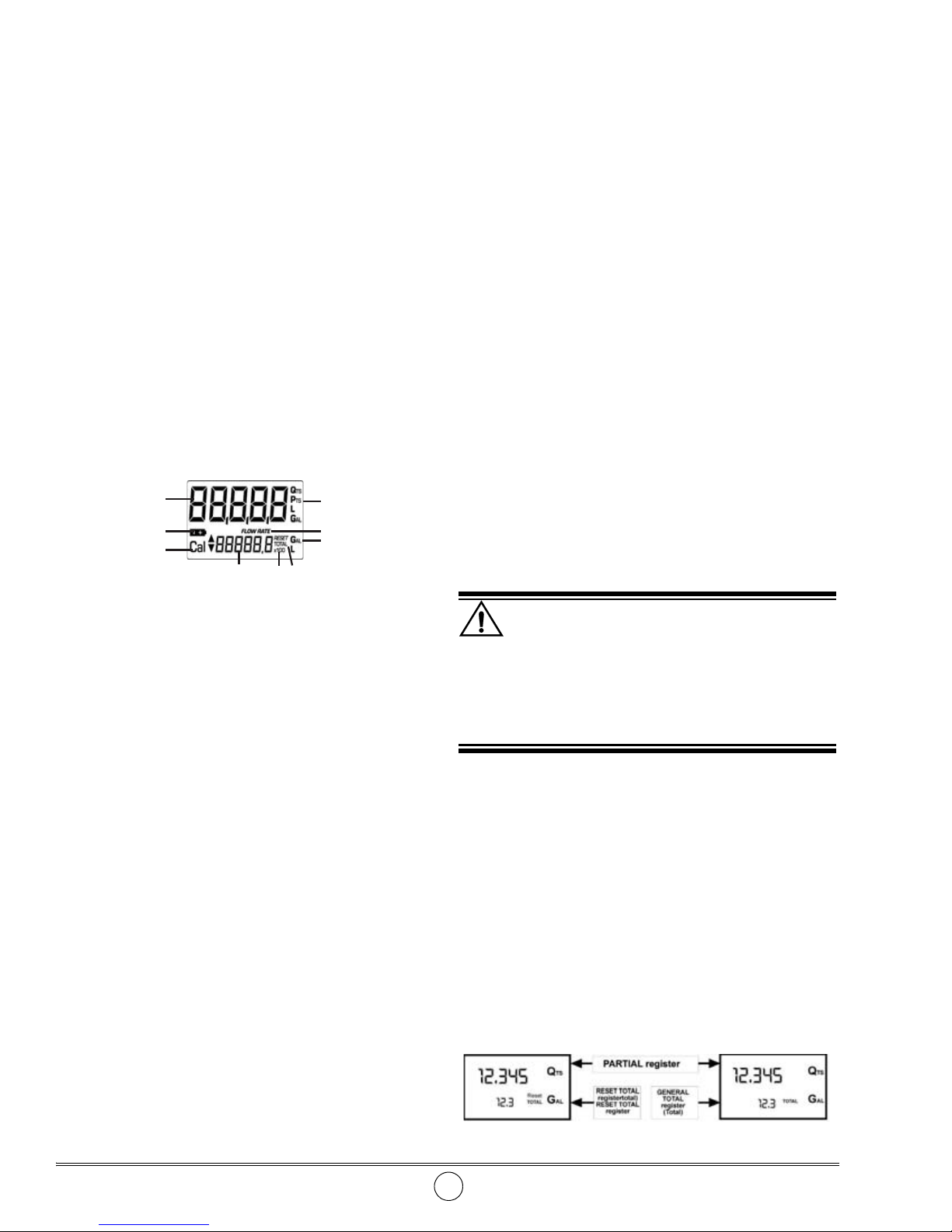
1. Partial register (5 digits with moving decimal FROM
0.1 to 99999) indicating the volume dispensed since the
reset button was last pressed;
2. Indication of battery charge;
3. Indication of calibration mode;
4. Totals register (6 digits with moving decimal point
FROM 0.1 to 999999), that can indicate two types of
Total: General Total that cannot be reset (TOTAL)
Resettable total (Reset TOTAL)
5. Indication of total multiplication factor (x10/x100)
6. Indication of type of total, (TOTAL/Reset TOTAL);
7. Indication of unit of measurement of Totals:
8. Indication of Flow Rate mode
9. Indication of unit of measurement of Partial:
User Buttons
The 8424 features two buttons (reset and cal) which
individually perform two main functions and, together,
other secondary functions. The main functions performed
are:
WARNING
At the female inlets, tighten the couplings at a
max. torque of 55N/m. At the female inlets, tighten
the couplings at a max. torque of 55N /m.
With The Gas-female Inlets, Do Not Use Conical
Threaded Couplings.
Daily Use
The only operations that need to be done for daily use
are partial and/or resettable total register resetting.
Occasionally the meter may need to be configured or
calibrated. To do so, please refer to the relevant sections.
Below are the two typical normal operation displays.
One display page shows the partial and reset total
registers. The other shows the partial and general total.
Switch over from resettable total to general total display is
automatic and tied to phases and times that are in factory
set and cannot be changed.
Revision (1-11) 2 Alemite, LLC
Flow Meter SER 8424
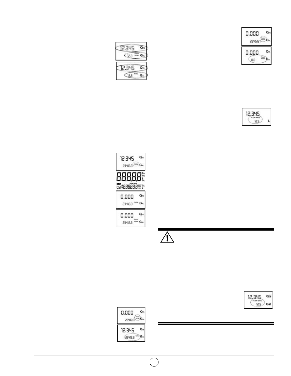
Dispensing in Normal Mode
Normal mode is the standard
dispensing. While the count is
made, the partial and resettable total
are displayed at the same time
(reset total).
Should one of the keys be
accidentally pressed during
dispensing, this will have no effect.
A few seconds after dispensing has ended, on the
lower register, the display switches from resettable
total to general total: the word reset above the word
total disappears, and the reset total is replaced by the
general total. This situation is called standby and
remains stable until the user operates the 8424 again.
Partial Reset
The partial register can be reset by
pressing the reset key when the meter
is in standby, meaning when the
display screen shows the word
“TOTAL”.
After pressing the reset key, during
reset, the display screen first of all
shows all the lit-up digits and then all
the digits that are not lit up.
At the end of the process, a display
page is first of all shown with the reset
partial and the reset total.
3. The meter starts to reset the partial
4. While the display page showing the
reset total is displayed Press the
reset key again for at least 1 second.
5. The display screen again shows all
the segments of the display
followed by all the switched-off segments and finally
shows the display page where the reset Reset Total is
shown.
Dispensing with Flow Rate Mode display
It is possible to dispense fluids,
displaying at the same time:
• The dispensed partial
• The Flow Rate in [Partial Unit/minute]
• As shown on the following display page:
Procedure for entering this mode:
• Wait for the Remote Display to go to Standby,
meaning the display screen shows Total only
• Quickly press the CAL key.
• Start dispensing
The flow rate is updated every 0.7 seconds.
Consequently, the display could be relatively unstable at
lower flow rates. The higher the flow rate, the more stable
the displayed value.
After a few moments, the reset total is replaced by the
non resettable Total.
Resetting the Reset Total
The reset total resetting operation can only be
performed after resetting the partial register. The reset
total can in fact be reset by pressing the reset key at length
while the display screen shows reset total as on the
following display page:
Schematically, the steps to be taken are:
1. W ait for the display to show normal
standby display page (with total
only displayed)
2. Press the reset key quickly
Alemite, LLC 3 Revision (1-11)
WARNING
The flow rate is measured with reference to the
unit of measurement of the Partial. For this reason,
in case the unit of measurement of the Partial
and Total being different, as in the example shown
below, it should be remembered that the indicated
flow rate relates to the unit of measurement of the
partial. In the example shown, the flow rate is
expressed in Qts/min. The word
“Gal” remaining alongside the flow
rate refers to the register of t he
Totals (Reset or NON Reset) which
are again displayed when exiting
from the flow rate reading mode.
To return to “Normal” mode, press the CAL key again.
 Loading...