

Alemite 7373 Service Manual
Service Guide
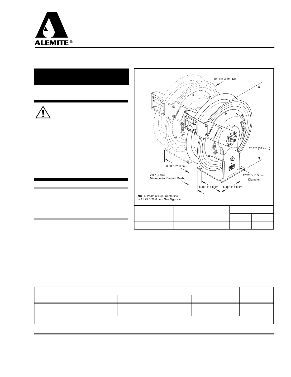
Double Post Fuel Hose Reel
Español............................. Página 9
Français..............................Page 17
Description
WARNING
Should reel model 7373 be used to
deliver gasoline or aircraft fuel, the:
• delivery and connecting hose must
contain a grounding wire
• entire fuel delivery system must be
properly grounded
This prevents the development of static electricity.
Personal injury can occur due to fire and/or
explosion.
7373
CAUTION
Install these reels at a height no greater than
16 feet (4.9 m) from the floor to comply with
the warranty.
Hose reel model 7373 is designed:
• for use on a lubrication truck to deliver fuel
(such as diesel fuel, aircraft fuel, and gasoline)
and lubricating oils
• to mount to a ceiling or wall
These reels are spring-powered and self-retracting. When the hose is extended, the reel can be
latched on either of two ratchet sections per revolution of the sheave. A pull releases the latch from the
ratchet and allows the hose to retract onto the reel.
Reel Package
Model
8081-K 7373 317868-30
Delivery hose length is designated by the dash number. Example: 317868-30 is 30 feet long.
Hose Reel
(Bare)
Part No. Description Electrically Conductive
3/4 " ID One-Wire Braid
3/4 " NPTF (m) x 3/4 " NPTF (m)
Ta bl e 1 Reel Package
Inlet Outlet (Low-Pressure Swivel)
3/4 " NPSM (m) 3/4 " NPSM (f) 300 21
Figure 1 Double Post Fuel Hose Reel Model 7373
IMPORTANT: The reel is grounded at the Swivel with a
Wave Washer and handles a maximum of 30 feet of hose.
Delivery Hose
Reel Max. Pressure
psi bar
Hose Stop
Yes 339389
670908
Alemite, LLC
167 Roweland Drive, Johnson City, Tennessee 37601
www.alemite.com
Copyright © 2005 by Alemite, LLC
This document contains confidential information that is the property of Alemite, LLC
and is not to be copied, used, or disclosed to others without express written permission.
SER 7373
Revision (6-11)
SER 7373 Double Post Fuel Hose Reel
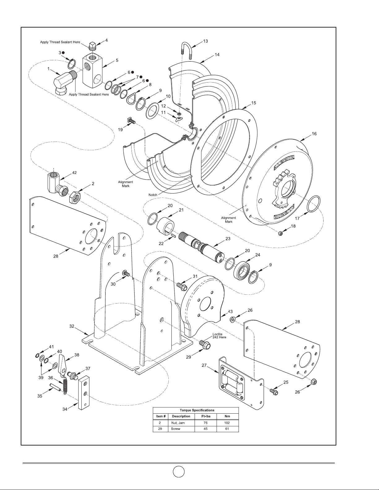
Figure 2 Double Post Fuel Hose Reel Model 7373 - Exploded View
Revision (6-11) 2 Alemite, LLC

Double Post Fuel Hose Reel SER 7373
Item
No.
10 339209 Washer 1
11 Nut, Wing, 1/4 " -20 2
12 Washer, 5/16 " 2
13 U-Bolt 1
14 339199-A Sheave Assembly (w/ Bearing and Gasket) 1
15 Gasket, Spring Case (Sponge Rubber) 1
16 339200-B Spring Assembly, Power 1
17 X171009-44 O-Ring, 2-1/2 " ID x 2-11/16 " OD 1 Pack of Ten
18 Nut, Elastic Stop, 10-32 6
19 Screw, 10-32 x 3/8 " 6
20 X171009-14 O-Ring, 1-1/4 " ID x 1-3/8 " OD 2 Pack of Ten
21 339197 Arbor, Spring 1
22 339521 Key, Square 1
23 Shaft 1
24 339193-1 Bearing, Ball (Zinc-Dichromate Plated) 1
25 Screw, Hex Flange, 5/16 " -18 x 5/8 " 4
26 Nut, Flange, 5/16 " -18 12
27 340278 Guide Assembly, Hose 1 See Figure 3
28 340244 Arm, Hose Guide 2
29 Screw, Hex Flange, 1/2 " -20 x 3/4 " 1
30 340280 Bolt, Round Head, 5/16 " -18 x 5/8 " 8
31 Screw, Hex Flange, 3/8 " -16 x 5/8 " 2
32 Frame, Double Post 1
34 Block, Pawl 1
35 Pin, Roll 1
36 339210 Spring, Pawl 1
37 Shaft, Pawl 1
38 Pawl 1
39 Washer 2
40 Spring, Wave 1
41 Ring, Retaining 1
42
43
Legend:
Part No. Description and Model Qty
1001-1212 90 ° Union, 3/4 " NPTF (m) x 3/4 " NPSM 2
1
2 340325
3 Ring, Retaining 1
4 Plug, Pipe 3/4 " NPTF (m) 1
5 339385 Body, Swivel 1
6 O-Ring, 1 " ID x 1-1/8 " OD 2
7 Quad-Ring, 7/8 " ID x 1-1/8 " OD 2
8 Washer, Wave 1
9 Ring, Retaining 2
340275 Cartridge, Pawl 1 Includes Items 34 - 41
340528-4 90 ° Union, 3/4 " NPTF (f) x 3/4 " NPSM
343080 Guard, Ratchet
Part numbers left blank are not available separately
designates a repair kit item
Nut, Jam
1
1
1
Repair Kit
Notes
Part No. Kit Symbol Description
393701 Kit, Low-Pressure Swivel Repair
Alemite, LLC 3 Revision (6-11)
SER 7373 Double Post Fuel Hose Reel
Installation
WARNING
Do not exceed the lowest pressure rating of
any component in the system.
Never point a control valve at any portion of your body
or another person. Lubricant discharged at high velocity can penetrate the skin and cause severe injury.
Should any lubricant appear to puncture the skin, get
medical care immediately.
Ensure all components are in operable condition.
Replace any suspect parts prior to operation.
Hold the delivery hose securely until the reel is securely
latched or fully retracted. Uncontrolled retraction can
result in personal injury.
1. Connect the delivery hose securely to 90 ° Un ion (1).
HINT: Orient the hose to allow its natural curve
to match the Sheave. This reduces torque load on
Power Spring Assembly (16).
2. Secure the delivery hose to the Sheave Assembly with
U-Bolt (13), Washers (12) and Wing Nuts (11).
IMPORTANT: Allow some slack on the hose
between the U-Bolt and the 90 ° Union.
3. Rotate the Sheave Assembly to wrap the hose completely
onto the reel.
• The clicking sound is the power spring bypassing the cam
on Spring Arbor (21).
4. Rotate the Sheave Assembly in the opposite direction 3 turns.
• This sets the power spring tension.
IMPORTANT: When the hose is fully extended
from the reel, the power spring should be a minimum of 1/2 turn from a fully wound condition.
5. Feed the end of the delivery hose through Hose Guide
Assembly (27).
6. Install and secure the hose stop.
7. Mount the reel assembly with the appropriate hardware as
required.
8. Adjust the hose stop to the desired position.
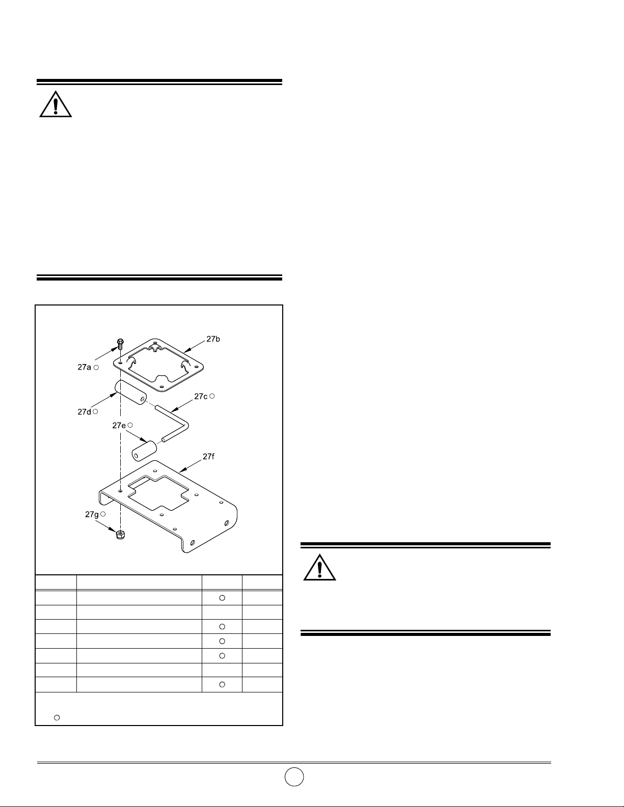
Item # Description Notes Qty
27a Screw 10-32 x 1/2 " 4
27b Retainer, Roller 1
27c Pin 2
27d Roller, Long 2
27e Roller, Short 2
27f Plate, Roller 1
27g
Legend:
Nut, Elastic Stop, 10 -32
Parts are not available separately
designates the parts available in Repair Kit 393696
9. Attach the connecting hose (with thread sealant) to the
distribution system and to the inlet of the reel as required.
10. Install the control valve (with thread sealant).
11. Pressurize the system and check for leaks.
Checking Spring Tension
Check to ensure the tension on the power spring is sufficient
to properly hold the hose stop against the Hose Guide.
Should the power spring tension require adjustment:
12. Release all pressure within the system.
WARNING
Disconnect the air supply line to the pump’s
motor.
Into an appropriate container, operate the control valve
to discharge remaining pressure within the system.
13. Remove the control valve and the hose stop from the delivery
hose.
4
14. Unlatch the reel and allow the free end of the delivery hose to
pass through the Hose Guide.
Figure 3 Hose Guide Assembly 340278 - Exploded View
Revision (6-11) 4 Alemite, LLC
Double Post Fuel Hose Reel SER 7373
CAUTION
Do not overwind the power spring. Too much tension
reduces the life of the spring.
15. Rotate the Sheave Assembly in the required direction.
16. Pass the free end of the hose through the Hose Guide.
17. Install the control valve and the hose stop.
18. Pressurize the system and check for leaks.
19. Check to ensure the tension on the power spring is sufficient
to properly hold the hose stop against the Hose Guide.
20. Repeat steps 12 - 19 until the proper tension is achieved.
Latch Lockout
Reel Over-Run
IMPORTANT: Do not extend the hose from the
reel too rapidly. Too much velocity can cause the
reel to over-run and latch.
Should latch lockout occur, pulling on the hose will not
release the latch mechanism.
With the reel latch in this condition it will be necessary to
have an assistant maintain tension on the hose while the latching
mechanism is manually released.
Maintenance
Read each step of the instructions carefully. Make sure a
proper understanding is achieved before proceeding.
WARNING
Release all pressure within the system prior to
performing any maintenance procedure.
Disconnect the air supply line to the pump’s motor.
Into an appropriate container, operate the control valve
to discharge the remaining pressure within the system..
Delivery Hose Replacement
1. Ex tend the delivery hose completely from the reel.
WARNING
Precautions must be taken to ensure the
Sheave Assembly remains engaged with the Power
Spring’s ratchet. To prevent movement either:
• instruct an assistant to grip the Sheave Assembly
securely with non-slip gloved hands or
• install a clamp on the Sheave Assembly
Personal injury can occur.
WARNING
The reel is under maximum spring tension.
Personal injury can occur.
1. Instruct the assistant to grip the hose securely with both
hands to prevent uncontrolled retraction.
2. Grip Sheave Assembly (14) securely with gloved hands.
3. Turn the Sheave Assembly in the direction just enough that
allows Pawl (38) to be free of tension from the ratchet on
Power Spring Assembly (16).
• This direction further increases tension on the power
spring.
4. While maintaining the position of the Sheave assembly with
one hand, move the Pawl away from the ratchet.
• Use a screwdriver or other suitable tool.
5. Instruct the assistant to allow the hose to retract slowly onto
the Sheave Assembly.
2. Remove the control valve and hose stop.
3. Disconnect the delivery hose from 90 ° Union (1).
4. Remove Wing Nuts (11) and Washers (12) that secure
U-Bolt (13) to the hose.
• Remove the hose.
5. Feed the end of the new delivery hose through Hose Guide
Assembly (27).
6. Connect the delivery hose to the 90 ° Union.
HINT: Orient the hose to allow its natural curve
to match the Sheave. This reduces torque load on
Power Spring Assembly (16).
7. Secure the delivery hose to the Sheave Assembly with
U-Bolt (13), Washers (12) and Wing Nuts (11).
8. Install the control valve (with thread sealant) and hose stop
to the delivery hose.
IMPORTANT: Allow some slack on the hose
between the U-Bolt and the 90 ° Union.
9. Pressurize the system and check for leaks.
10. Carefully release the Sheave Assembly and retract the hose
onto the reel.
11. Check the Spring Tension.
• Please refer to the section entitled Installation for details.
Alemite, LLC 5 Revision (6-11)

SER 7373 Double Post Fuel Hose Reel
Disassembly
WARNING
Release the tension on the power spring. Per-
sonal injury can occur.
Refer to Figure 2, 3 and 4 for disassembly.
WARNING
Do not attempt to disassemble Power Spring
Assembly (16). Personal injury can occur.
Assembly
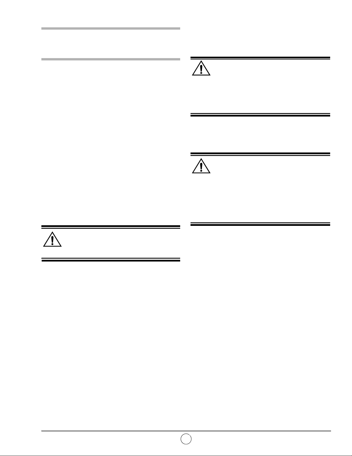
NOTE: Prior to assembly, certain components
require lubrication. Refer to Table 2 for details.
Refer to Figures 2, 3 and 4 for assembly.
CAUTION
Do not operate without Ratchet Guard (43). Per-
sonal injury can occur.
Bench Test
While facing the reel inlet, turn the reel in a clockwise
direction and allow the ratchet to latch onto Pawl (38).
If the reel does not tension or latch properly, refer to the
Troubleshooting Chart.
Components Lubricated with NLGI 2 EP Lithium Grease
Item No. Description
3 Retaining Ring
5 Bore of Swivel Body
6 O-Ring, 1 " ID x 1-1/8 " OD
7 Quad-Ring, 7/8 " ID x 1-1/8 " OD
8 Wave Washer
16 Power Spring’s ratchet teeth
37 Bearing surface of Pawl Shaft
36 Hooks of Pawl Spring
40 Wave Spring
Components Lubricated in Oil
17
20 O-Ring, 1-1/4 " ID x 1-3/8 " OD
O-Ring, 2-1/2 " ID x 2-11/16 " OD
Ta ble 2 Lubricated Components
Figure 4 Double Post Fuel Hose Reel Model 7373 - Section View
Revision (6-11) 6 Alemite, LLC
Double Post Fuel Hose Reel SER 7373
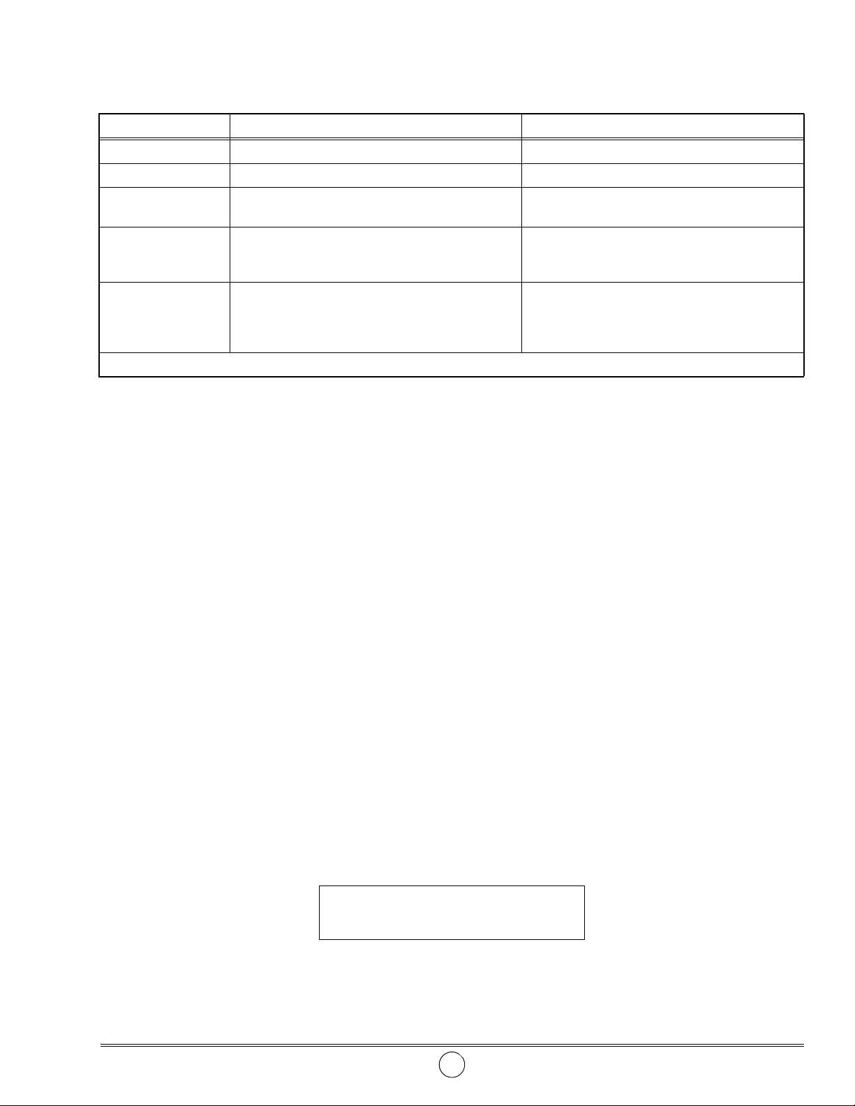
Troubleshooting Chart
Indications Possible Problems Solution
Reel does not latch Pawl Spring (36) broken or not attached to Pawl (38) Replace or secure Pawl Spring (36)
Reel does not retract Power spring broken* Replace Power Spring Assembly (16)
Reel retracts partially 1. Improper power spring tension
2. Hose length greater than 30 ' (9.1 m)
Reel does not unlatch
after maximum length
of hose is removed
Material leakage at
Swivel Assemb ly
* The possible causes for broken components are listed in italics
1. Power spring wound solid
2. Hose removed from the reel too quickly
(Reel Over-Run)
1. Connection not sufficiently tight and / or thread
sealant missing at 90 ° Union (1) or Pipe Plug (4)
2. Worn or damaged Quad-Rings (7)
3. Worn or damaged Swivel Body (5)
1. Adjust tension
2. Install a hose not to exceed 30 ' (9.1 m)
1. Decrease power spring pre-wind
2. Remove hose slowly when close to being fully
extended
1. Apply sealant to male threads of 90 ° Union (1)
or Pipe Plug (4) and tighten connections
2. Use Repair Kit 393701
3. Replace Swivel Body (5)
Changes Since Last Printing
Added Ratchet Guard & updated repair parts
Alemite, LLC 7 Revision (6-11)
SER 7373 Double Post Fuel Hose Reel
Revision (6-11) 8 Alemite, LLC
 Loading...