

Alemite 7342 Service Manual

Service Guide
High-Capacity Reel
Description
WARNING
Should reel model 7342 be used to deliver
gasoline or aircraft fuel, the:
• delivery and connecting hose must c ontain a
grounding wire
• entire fuel delivery system must be properly
grounded
This prevents the build-up of static electricity.
Personal injury can occur due to fire an d/or e xp lo-
sion.
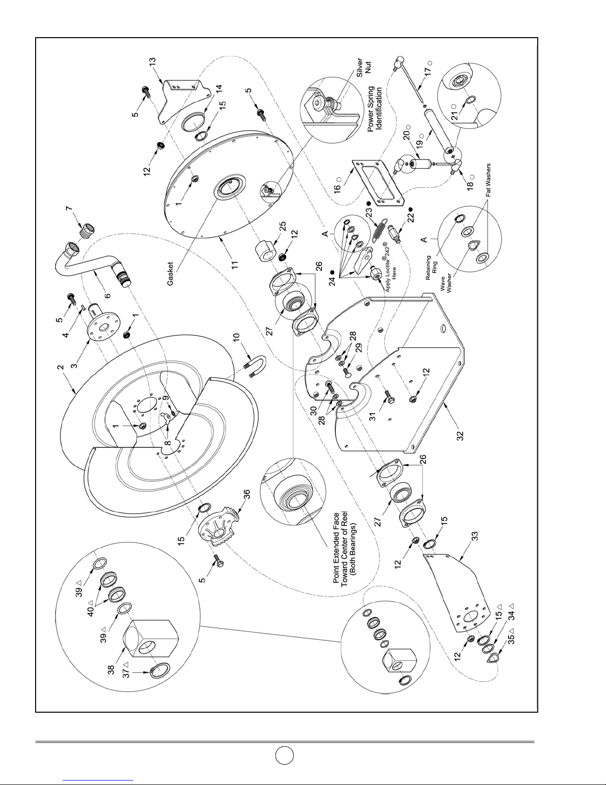
NOTE: The reel is grounded at the swivel
with a wave washer. See Figure 2.
7342
High-capacity hose reel model 7342 is designed to:
• deliver fuel (such as diesel fuel, aircraft fuel, and
gasoline) and lubricating oils.
• mount to a lubrication truck or to a ceiling* or wall.
This reel mounts as a single unit or in banks of as
many as required. See Figure 4 for details.
NOTE: The Hose Guide Arms can attach to the
Base Assembly in five (5) different positions.
This model reel is spring-powered and self-retracting.
When the hose is extended, the reel can be latched on
either of two ratchet sections per revolution of the sheave.
A pull releases the latch from the ratchet and allow s the
hose to retract onto the reel.
This model reel manages a maximum length of
delivery hose as indicated in Ta bl e 1 .
Delivery Hose Description Maximum Length of Hose in Feet
3/4 “ID Single-Wire Braid 70
1 “ID Single-Wire Braid
50
1 “ID Fuel
Ta ble 1 Delivery Hose Capacity for Reel Model 7342
Inlet (Swivel) Outlet
Reel Max. Pressure
psi Bars
1 " NPTF (f) 1 " NPSM (f) * 1000 69
* A bushing (included) allows the outlet to be reduced to 3/4 " NPTF (f)
Figure 1 High-Capacity Reel Model 7342
CAUTION
* The base of the reel must be at a height no greater
than 16 feet (4.9 m) from the floor to comply with the
warranty.
167 Roweland Drive, Johnson City, Tennessee 37601
This document contains confidential information that is the property of Alemite LLC
670784 and is not to be copied, used, or disclosed to others without express written permission. Revision (10-13)
Alemite LLC
www.alemite.com
Copyright © 2010 by Alemite LLC
SER 7342
SER 7342 High-Capacity Reel
Figure 2 High-Capacity Reel Model 7342 - Exploded View
Revision (10-13) 2 Alemite LLC
High-Capacity Reel SER 7342
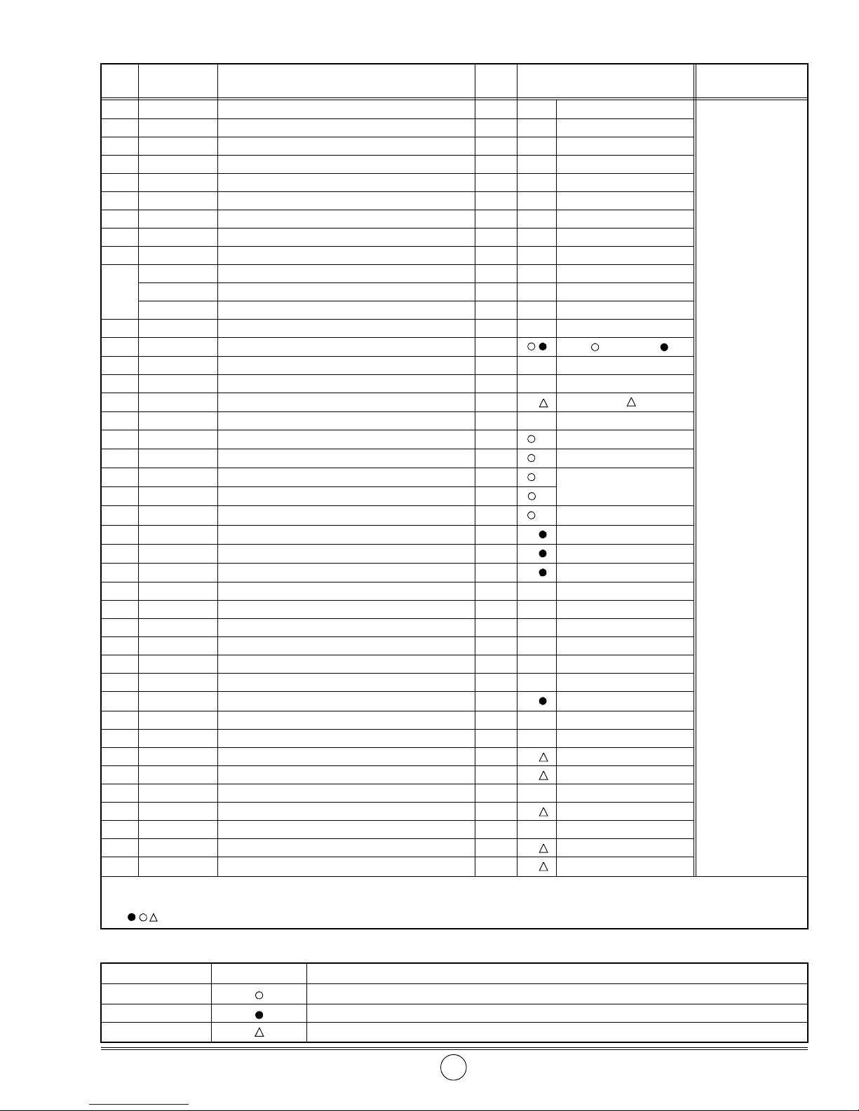
Item
No.
Part No. Description Qty Notes
1 Nut, Flange 5/16 " -18 16
2 Sheave Assembly 1
3 339464 Shaft and Flange Assembly 1
Numeric Order
Part # (Item #)
14534 (9)
50876 (8)
171000-5 (21)
4 339521 Key, Square 1 171007-32 (37)
5 Screw, 5/16 " -18 x 3/4 " 20 171007-33 (15)
6 339476 Shaft and Riser Assembly 1
171009-13 (39)
7 320353 Bushing, 1 " NPTF (m) x 3/4 " NPTF (f) 1 Use w/ 3/4 " hose 320353 (7)
8 Nut, Wing, 1/4 " -20 2 339197 (25)
9 Washer, 5/16 " 2
339208 (28)
339219-1 U-Bolt, 1-1/8 " 1 Use w/ 3/4 " hose 339209 (34)
10
339219-2 U-Bolt, 1-1/2 " 1 Use w/ 1 " hose 339210 (23)
339219-3 U-Bolt, 1-1/4 " 1 Use w/ 1 " hose 339219-1 (10)
11 339469-2 Spring Assembly, Power 1 Includes Gasket 339219-2 (10)
12 Nut, Flange 3/8 " -16 11
4 in kit, 1 in kit
13 Arm, Short 1
14 339455 Plug, Button 1
15 171007-33 Ring, Retaining 4
1 in
kit
16 Plate, Hose Guide 1
17 Post and Shaft Assembly, Long 2
18 Post and Shaft Assembly, Short 2
19 Roller Assembly, Long 2
20 Roller Assembly, Short 2
21 O-Ring, 1/4 " ID x 3/8 " OD 8
22 Post, Spring 1
23 339210 Spring, Extension 1
24 Pawl and Shaft Assembly 1
Includes Item 21
25 339197 Arbor, Spring 1
26 339457 Housing, Bearing 2 Includes Two Halves
27 339456 Bearing 2
28 Washer, 0.445 " ID x 0.75" OD 8
339219-3 (10)
339435 (32)
339439 (24)
339441 (22)
339443 (2)
339446 (13)
339447 (33)
339448 (16)
339451-1 (20)
339451-2 (19)
339455 (14)
339456 (27)
339457 (26)
339460 (31)
339461 (5)
339462 (12)
339463 (29)
29 Bolt, Ribbed-Neck, 3/8 " -16 x 3/4 " 2 339464 (3)
30 Bolt, Ribbed-Neck, 3/8 " -16 x 1-1/4 " 2 339467 (36)
31 Screw, 1/2 " -13 x 3/4 " 1
339469-2 (11)
32 Base Assembly 1 339476 (6)
33 Arm, Long 1 w/o Decal 339481 (38)
34 339209 Washer 1 339483 (35)
35 339483 Washer, Wave 1
36 339467 Ratchet 1
37 171007-32 Ring, Retaining 1
38 339481 Body, Swivel 1
339484 (30)
339516-1 (18)
339516-2 (17)
339520 (40)
39 O-Ring, 1-3/16 " ID x 1-5/16 " OD 2 339521 (4)
40 T-Seal 2
387370 (1)
Legend:
Part numbers left blank (or in italics) are not available separately
designates a repair kit item
Part No. Kit Symbol Description
393727 Kit, Hose Guide
393724 Kit, Pawl and Shaft Assembly
393725 Kit, Swivel Repair
Alemite LLC 3 Revision (10-13)
Repair Kits

SER 7342 High-Capacity Reel
IMPORTANT: Prior to performing any maintenance procedure, the following safety precautions must be observed. Personal injury
may occur.
WARNING
Release all pressure within the system prior
to performing any overhaul procedure.
• Disconnect the air supply line to the pump’s
motor.
• Into an appropriate container, operate the control valve to discharge remaining pressure
within the system.
Read each step of the instructions carefully. Make
sure a proper understanding is achieved before
proceeding.
Overhaul
IMPORTANT: Make sure all pressure is
released within the system.
NOTE: Refer to Figure 2 for component
identification on all overhaul procedures.
Hose Guide Assembly
7. Remove Nuts (12) that secure Post and Shaft
Assemblies (17) and (18) to Hose Guide Plate (16).
• Remove each Post and Shaft Assembly from the
Hose Guide Plate.
8. Remove Roller Assemblies (19) and (20) from each
Post and Shaft Assembly as required.
9. Remove O-Rings (21) from each Roller Assembly as
required.
HINT: Use an small flat-head screwdriver.
Arms and Power Spring Assembly
10. Remove Nuts (12) that secure Long Arm (33) to Bolts
(30).
• Remove the Arm from the Bolts.
11. Remove Nuts (1) and Screws (5) that secure Short
Arm (13) to Power Spring Assembly (11) as requir ed.
• Remove the Arm from the Power Spring Assembly.
12. Remove Screws (5) that secure the Power Spring
Assembly to Base Assembly (32).
• Remove the Power Spring Assembly from the Base
Assembly.
Disassembly
IMPORTANT: Prior to disassembly, release
tension on the power spring.
1. Remove the hose stop and the control valve from the
delivery hose.
2. Pull on the delivery hose to unlatch the reel.
3. Allow the delivery hose to retract onto the reel.
4. Turn the reel in the same direction until the power
spring bypasses Spring Arbor (25).
• A pronounced “click” will sound.
Swivel Assembly
5. Remove Retaining Ring (37) that secures Swivel Body
(38) to Shaft and Riser Assembly (6).
• Remove the Swivel Body.
6. From the Shaft and Riser Assembly remove:
• O-Ring (39). . . . . . . . . . . . . . . . . . . . . . . . . . . .Qty 2
•T-Seal (40) . . . . . . . . . . . . . . . . . . . . . . . . . . . . Qty 2
• Wave Washer (35). . . . . . . . . . . . . . . . . . . . . . .Qty 1
•Washer (34) . . . . . . . . . . . . . . . . . . . . . . . . . . . .Qty 1
• Retaining Ring (15) . . . . . . . . . . . . . . . . . . . . .Qty 2
WARNING
Do not attempt to disassemble the Power
Spring Assembly. Personal injury can occur.
Delivery Hose
13. Pull the delivery hose from Sheave Assembly (2).
14. Remove Wing Nuts (8) and Washers (9) that secure
U-Bolt (10) to the Sheave Assembly.
• Remove the U-Bolt from the Sheave Assembly.
15. Disconnect the delivery hose from the Shaft and Riser
Assembly.
• Remove the delivery hose from the Sheave
Assembly.
16. Remove Bushing (7) [if used] from the delivery hose
as required.
Arbor and Bearings
17. Remove Retaining Ring (15) that secures Arbor (25)
to Shaft and Flange Assembly (3).
• Remove the Arbor from the Shaft and Flange
Assembly.
Revision (10-13) 4 Alemite LLC
 Loading...