

Alemite 3679 Service Manual
Service Guide
Electronic Meter
Description
CAUTION
Do not operate this meter with an antifreeze and water mixture.
Meter will not register properly.
Meter model 3679 is designed to measure a variety of fluids that
include motor oils (SAE 5-50), gear oils (SAE 80-240), and automatictransmission fluid.
The meter is totally electronic except for the oval gear metering
mechanism. The electronic register is powered by two 1-1/2 Volt AAA
alkaline batteries.
The meter can be programmed to register in:
• pints, quarts, or gallons, and totalize in gallons
• liters and totalize in liters
NOTE: The meter is factory programmed to register in
quarts and totalize in gallons.
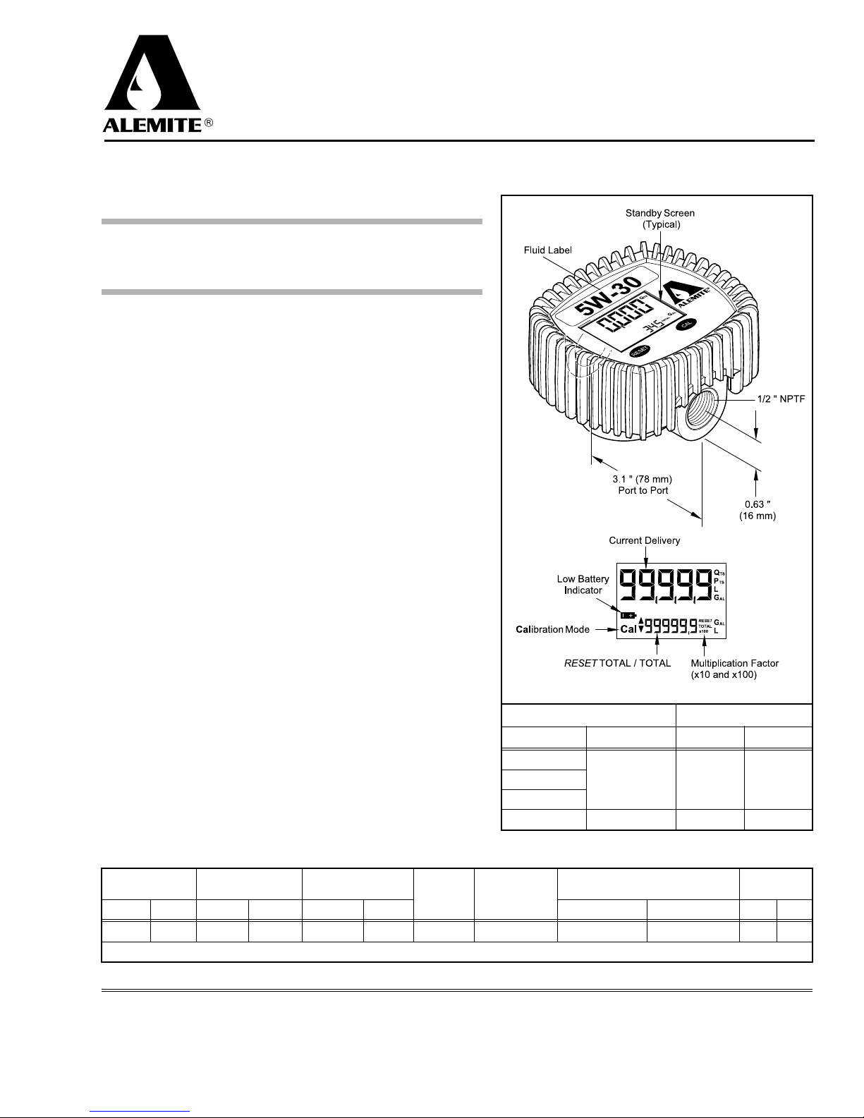
A liquid-crystal display shows the following amounts of fluid
dispensed by volume:
• Current delivery
• RESET TOTAL (momentary)
•TOTAL
All three amounts display with a floating decimal point.
• Current delivery (0.000 to 99999)
• RESET TOTAL and TOTAL (0.0 to 999999)
The meter’s non-volatile memory retains the unit of measure, totals,
and calibration factor during battery replacement.
3679
Operation
To zero the current delivery and RESET TOTAL the meter must be
in Standby. See Figure 1.
Press the Reset button to zero the current delivery.
When the RESET TOTAL is required to be reset:
1. Press the Reset button.
•The RESET TOTAL displays for 5 seconds.
2. Press and hold the Reset button while the RESET TOTAL displays.
•The RESET TOTAL is reset to zero.
The RESET TOTAL and TOTAL update automatically during
fluid delivery.
Max. Operating
Pressure
psi bar ° F ° C ° F ° C in. cm lbs kg
1000 70 -4 to 158 -20 to 70 23 to 122 -5 to 50 ± 1% 1% 3.7 x 4.2 x 2.4 9.4 x 10.7 x 6.1 0.83 0.38
* With SAE 10W Oil at 68° F (20° C)
670890
Storage
Temperature
This document contains confidential information that is the property of Alemite, LLC
and is not to be copied, used, or disclosed to others without express written permission.
Programmable Units of Measure Flow Rate in Units / Min.
Current Totalizer Min. Max.
pint
quart
gallon
liter liter 1 liter 30 liters
Figure 1 Electronic Meter Model 3679
Operating
Temperature
Ta ble 1 Electronic Meter Model 3679 Specifications
167 Roweland Drive, Johnson City, Tennessee 37601
Copyright © 2010 by Alemite, LLC
Accuracy* Repeatability*
Alemite, LLC
www.alemite.com
Dimensions (w/ Guard)
gallon
L x W x H
1/4 gallon 8 gallons
Weight
SER 3679
Revision (5-10)

SER 3679 Electronic Meter
Meter Programming
IMPORTANT: The meter must be in Standby to
begin any programming function. See Figure 1.
Change Unit of Measure
1. Press and hold the Cal and Reset buttons at the same time.
•The Unit screen appears.
2. Repeatedly press the Reset button.
• The screen scrolls through the available units of measure
(see Figure 1).
Once the desired units of measure appear:
3. Press and hold the Cal button.
• The chosen units of measure are stored in memory and
active.
• The meter cycles to Standby.
Calibration Factor Determination
To determine the meter’s calibration factor* in use:
1. Press and hold the Cal button.
• The calibration factor screen appears.
The word Fact (short for factory) indicates the calibration set
at the factory is in use (1.000). User indicates the Factory
calibration factor has been superseded and is in use.
If the meter indicates User but the Factory calibration factor
(1.000) is required:
2. Press the Reset button.
• The screen changes from the User calibration factor to the
Factory calibration factor.
3. Press the Cal button.
• The meter cycles to Standby.
•The Factory calibration factor (1.000) is active.
•The User calibration factor is deleted from memory.
* The calibration factor is a value that the meter uses to
calculate the amount of fluid dispensed.
User Calibration
Variables that cause a meter to require recalibration are:
• fluid viscosity
• fluid flow rate
• back-pressure
Field Calibration
This method of programming the meter requires dispensing a
known quantity of fluid.
1. Press and hold the Cal button.
• The calibration factor screen appears.
2. Press and hold the Reset button.
•The Field screen appears.
3. Dispense any amount of fluid greater than 5 quarts or liters
into an appropriate-sized graduated beaker.
• Dispense the fluid at the normal flow rate.
Should the field value match the dispensed value:
4. Press the Reset button.
• An upward arrow appears.
5. Press and hold the Reset button.
• The meter cycles to Standby.
The calibration factor remains the same.
If the field value does not match the actual amount:
6. Press the Reset button.
• An upward arrow appears.
This arrow enables the user to increase the field value.
7. Press the Reset button again to change the direction of the
arrow.
• A downward arrow appears.
This arrow enables the user to de crease the value .
With the proper arrow chosen:
8. Press the Cal button.
• The value changes one digit.
NOTE: Press and hold the Cal button to change
the value at a faster rate.
Once the required value displays:
9. Press and hold the Reset button.
•The User calibration factor is stored in memory and active.
• The meter cycles to Standby.
Direct Calibration
This method of calibration is useful to correct an inaccuracy
of a known percentage.
For example, if the calibration factor is set at 1.000 and the
meter registers more than the actual amount dispensed by 5%:
• the calibration factor should be decreased to 0.950
(1.000 x 0.95 = 0.950).
Conversely, if the meter registers less that the actual amount
dispensed by 5%:
• the calibration factor should be increased to 1.050
(1.000 x 1.05 = 1.050).
To program a calculated calibration factor into the meter:
1. Press and hold the Cal button.
• The calibration factor screen appears.
2. Press and hold the Reset button.
•The Field screen appears.
3. Press and hold the Reset button once again.
•The Direct screen appears with an upward arrow.
This arrow enables the user to increase the direct value.
4. Repeat steps 7 through 9 above.
Revision (5-10) 2 Alemite, LLC
Electronic Meter SER 3679
Installation
WARNING
Prior to installation, the following safety
precautions must be observed. Personal injury can
occur.
Do not exceed the pressure rating of any component
in the system.
Protect all fluid and air supply lines from puncture
or damage. Check all lines for weak or worn conditions prior to use.
Never point a control valve at any portion of your
body or another person. Accidental discharge of
pressure and/or material can result in personal
injury.
Read each step of the instructions carefully. Make
sure a proper understanding is achieved before proceeding.
CAUTION
Install a 40-micron or finer filter at the inlet side of
this meter. Jammed gears, damage to components,
or inaccurate readings can occur.
Maintenance
WARNING
Release all pressure within the system prior to per-
forming any maintenance procedure.
Repairs should only be performed by a qualified person
using original repair parts.
Read each step of the instructions carefully. Make sure a
proper understanding is achieved before proceeding.
Battery Replacement
NOTE: All meter values remain in memory.
The batteries should be replaced once the battery icon appears on
the display. See Figure 1.
IMPORTANT: The meter will no longer register
should the battery icon begin to flash.
WARNING
Recycle or discard the used batteries properly. Do
not burn or puncture the batteries. Toxic materials may be
emitted which can cause personal injury.
Prior to meter installation, flush all contaminants by
pumping fluid through the system.
Apply thread sealant to all male pipe threads upon
installation.
CAUTION
Avoid touching the flat surfaces of the new batteries. Skin
oils can cause battery deterioration. Clean any suspect battery with alcohol prior to installation.
Install the new Batteries as indicated on the bottom of the meter.
All values remain the same including the Current delivery.
Metering Gear Replacement
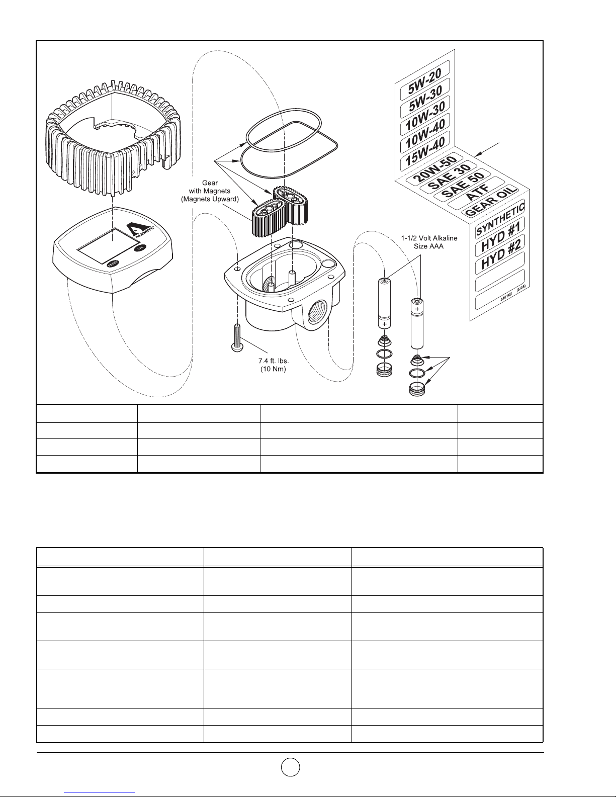
IMPORTANT: Install the gear with the magnets (magnets upward) onto the left post of the body as shown
on Figure 2.
Install the additional gear perpendicular to the magnet gear. Rotate the gear assembly to ensure the gears
are properly positioned.
Alemite, LLC 3 Revision (5-10)
Changes Since Last Printing
Kit part number updated
SER 3679 Electronic Meter
1
2
3
Item No. Part No. Description Quantity
1 393772-9 Kit, Oval Gear 1
2 340162
3
393772-12 Kit, Battery Cap 2
Figure 2 Electronic Meter Model 3679 - Exploded View
Troubleshooting Chart
Meter Indications Possible Problems Solution
Battery icon appears solid or flashes on
display or LCD values are faded
Meter does not measure accurately Incorrect calibration factor Recalibrate the meter
Display blank Batterie s installed incorrectly Install the batteries as indicated on the bottom of
Reduced or zero flow 1. Gears jammed
Meter does not count and the flow rate
is normal
Err 1 flashing Damaged register Replace meter
Err 2 displays Temporary lapse in data calculation Wait until the register updates automatically
1. Weak batteries
2. Dirty contacts
2. Clogged system
1. Gears installed incorrectly
2. Register defective
Labels, Fluid 1
1. Replace batteries
2. Clean batteries and terminals
the meter
1. Overhaul metering gear cavity
2. Clean system filter
1. Install the magnet gear (magnets upward) onto
the left post of the body. See Figure 2.
2. Replace meter
Revision (5-10) 4 Alemite, LLC
 Loading...