

Page 1
Installation
and
Programming
Manual
EAR 1000/2 000
ADRA 1000/ 2000
Page 2

Page 3

EAR 1000/2000 and ADRA 1000/2000
Installation and Programming Manual
Release 2 June 2002
Page 4

NOTICE
This publication refers to the EAR 1000/2000 and the ADRA 1000/2000, Release 2.
Additional copies of this manual may be obtained from Aleen Technologies
Reproduction of this manual or parts thereof without written permission from Aleen
Technologies is strictly prohibited.
Aleen Technologies reserves the right to modify the hardware and software described in
the manual without prior notice. However, changes made to the hardware or software
described do not necessarily render this publication invalid.
WARRANTY
In the event that the product proves to be defective in workmanship or materials within a
period of one year from date of shipment, Aleen Technologies shall repair or replace the
product at its discretion. Transportation will be the responsibility of the dealer/distributor.
Under no circumstances shall Aleen Technologies be liable for consequential or
special damages, loss of revenue or user/dealer expenses arising out of or in
connection with the use or performance of the product, whether based on contract,
tort, or any other legal agreement.
The following shall void the above warranty: malfunctions resulting from fire, accident,
neglect, abuse, or acts of God; use of improper electrical power; or repair of, tampering
with or alteration of the product by anyone other than Aleen Technologies personnel.
Page 5

TABLE OF CONTENTS
1.
INTRODUCTION.............................................................................................1-1
SECTION I
EAR 1000/2000 INSTALLATION AND PROGRAMMING
2.
OVERVIEW OF EAR 1000/2000....................................................................2-1
2.1 Features and Services........................................................................................2-1
3.
DESCRIPTION AND INSTALLATION..........................................................3-1
3.1 Physical Description..........................................................................................3-1
3.1.1 Bottom Panel.....................................................................................................3-1
3.1.2 Front Panel........................................................................................................3-2
3.2 Installation.........................................................................................................3-3
3.2.1 Installing the EAR 1000/2000...........................................................................3-3
4.
DTMF PROGRAMMING.................................................................................4-1
4.1 Entering and Exiting the Programming Mode...................................................4-1
4.2 DTMF Programming Commands......................................................................4-2
4.2.1 Script Messages.................................................................................................4-2
4.2.2 PBX Parameters................................................................................................4-4
EAR/ADRA Install ation and Programming Manual i
Page 6

Table of Contents
4.2.3 Menus Handling............................................................................................... 4-6
4.2.4 Busy Menu Handling........................................................................................4-8
4.2.5 Advanced Features........................................................................................... 4-9
5.
CHANGING THE OPENING GREETING..................................................... 5-1
6.
PROGRAMMING EXAMPLE........................................................................ 6-1
SECTION II
ADRA 1000/2000 INSTALLATION AND PROGRAMMING.................................. 1
7.
OVERVIEW OF ADRA 1000/2000................................................................ 7-1
7.1 Features and Services....................................................................................... 7-1
8.
DESCRIPTION AND INSTALLATION ......................................................... 8-1
8.1 Physical Description......................................................................................... 8-1
8.1.1 Bottom Panel.................................................................................................... 8-1
8.1.2 Front Panel.......................................................................................................8-2
8.2 Installation........................................................................................................ 8-3
8.2.1 Installing the ADRA 1000/2000....................................................................... 8-3
9.
DTMF PROGRAMMING................................................................................9-1
9.1 Entering and Exiting the Programming Mode.................................................. 9-1
9.2 DTMF Programming Commands..................................................................... 9-2
ii EAR/ADRA Install ation and Programming Manual
Page 7

Table of Contents
9.2.1 Script Messages.................................................................................................9-2
9.2.2 PBX Parameters................................................................................................9-4
9.2.3 Greeting Handling.............................................................................................9-6
9.2.4 Busy Menu Handling........................................................................................9-7
9.2.5 Advanced Features ............................................................................................9-8
10. CHANGING THE OPENING GREETING....................................................10-1
APPENDIX A EAR/ADRA SPECIFICATIONS........................................................A-1
EAR/ADRA Installation and P rogramming Manual iii
Page 8

Page 9

1. INTRODUCTION
The EAR 1000/2000 is a small standalone Automated Attendant system. The
ADRA 1000/2000 is a small, stand alone Voice Announcer System. Both systems
are developed by ITS, a leader in t he field of voice processing systems and PBX
peripheral products. The EAR 1000/2000 and ADRA 1000/2000 incorporate state
of the art technology, including DSP, flash memory and SMT production.
This guide provides installation and programming instructions for both the
EAR 1000/2000 and ADRA 1000/2000. See Section I for instructions about
EAR 1000/2000; see Section II for instructions about ADRA 1000/2000.
EAR/ADRA Install ation and Programming Manual 1-1
Page 10

Page 11

SECTION I:
EAR 1000/2000
Installation and Programming
Page 12

Page 13
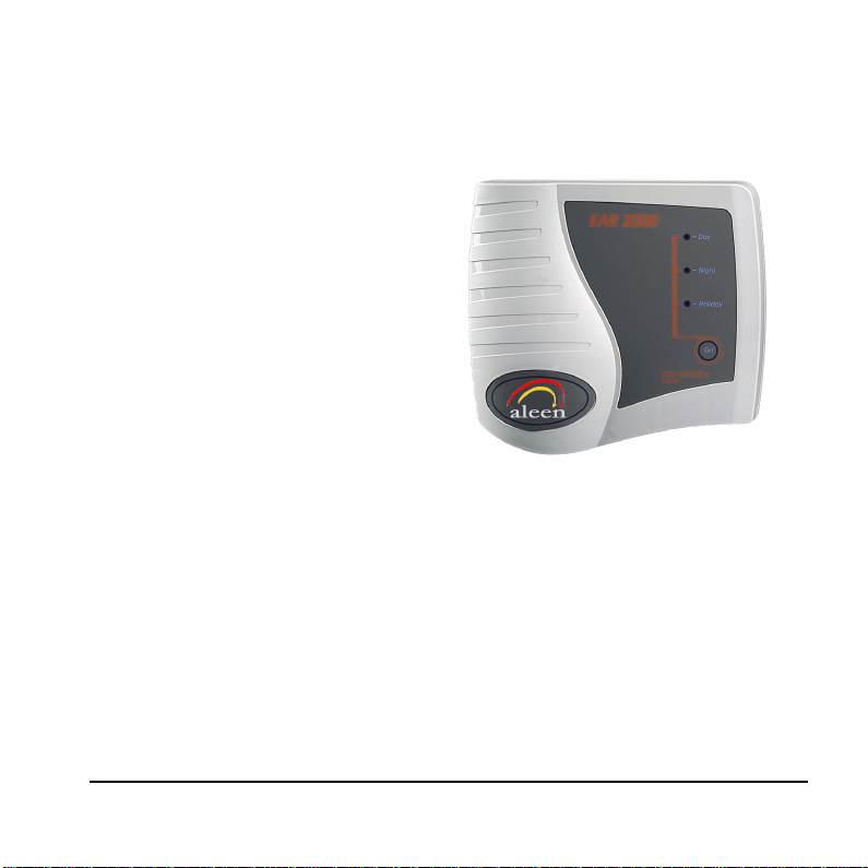
2. OVERVIEW OF EAR 1000/2000
The EAR 1000 is a one port auto
attendant system. The EAR 2000 is
a two port auto attendant system.
Both systems have 9 minutes of
recording time.
The EAR 1000/2000 can be
integrated with most types of PBX
through the analog ports and
programmed by a touch-tone
telephone.
Figure 2-1. EAR 2000 General View
2.1 Features and Services
The EAR 1000/2000’s features includes the following features:
• Opening Greetings: Day, Night, Holiday for each line.
• Call Transfer
The system administrator can program the EAR 1000/2000 to transfer the
calls to extensions in one of the following modes:
EAR 1000/2000 Installati on and P rogramming Manual 2-1
Page 14

Overview of EAR 1000/2000
− Non-Supervised. The EAR 1000/2000 transfers the call immediately
without verifying the status of the extension.
− Semi-Supervised. The EAR 1000/2000 checks for a busy signal before
transferring the call to the extension.
• Up to 9 minutes of recording time.
• High quality recording.
• Non-volatile memory (Flash memory).
• Adjustable flash time.
• Busy detect using call progress tone or DTMF codes.
• Busy menu play back.
• Remote programming and recording.
• Simple operation and maintenance.
2-2 EAR 1000/2000 Installation and Programming Manual
Page 15
3. DESCRIPTION AND INSTALLATION
3.1 Physical Description
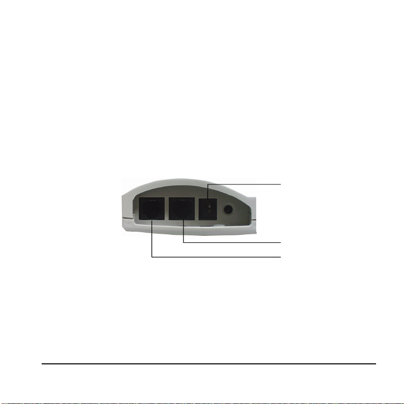
The functional components of the EAR 1000/2000 are located in its bottom side
panel. The LEDs are located on the front panel. The back panel has two indented
holes for wall mounting.
3.1.1 Bottom Panel
Ear 2000 Only
Figure 3-1. EAR 1000/2000 Bottom P anel
EAR 1000/2000 Installati on and Programming Manual 3-1
9VDC
Line 1
Line 2
Page 16
Description and installation
The following description corresponds to the labels in Figure 3-1.
1. Power Supply Connector Connects the EAR 1000/2000 to the external
power supply
2. 1/2 RJ-11 Sockets Connects the EAR 1000/2000 to PBX extensions
3.1.2 Front Panel
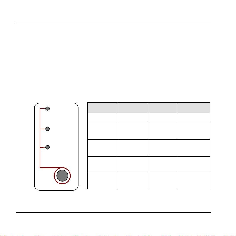
The following f i g ure a nd ta ble de sc r ibe the function of the three LE DS on the front
panel.
- Day
STATUS DAY NIGHT HOLIDAY
Day Mode On Off Off
- Night
- Holiday
Set
Night
Mode
Holiday
Mode
System
1
Error
System
1
Error
Off On Off
Off Off On
Off Flashing Off
Flashing Flashing Flashing
Figure 3-2. LEDs on
the Front Panel
3-2 EAR 1000/2000 Installation and Programming Manual
1
Please contact your loc al deal er.
Page 17
Description and installation
3.2 Installation
The EAR 1000/2000 is delivered completely assembled. It is designed for
mounting on a wall, close to the PBX.
3.2.1 Installing the EAR 1000/2000
To install the EAR 1000/2000:
1. Mount the unit on a wall close to the PBX cabinet. Use the drill template to
place the two screws.
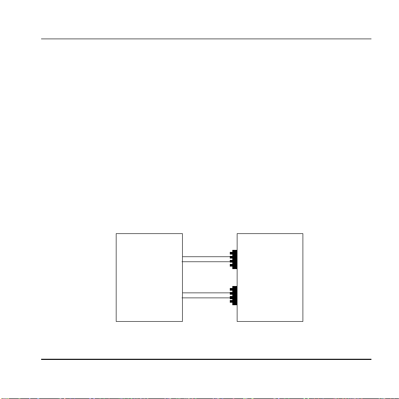
2. Connect the RJ-11 connector on one end of the cables to the RJ-11 sockets on
the bottom panel of the EAR 1000/2000. Connect the other end of the cables
to one analog telephone line on the Main Distribution Frame (MDF) of the
PBX (see Figure
3-3).
Main Distribution
Frame of the BPX
Line 1
Line 2
(Ear 2000 Only)
EAR 1000/2000
Bottom Panel
4-pin
RJ-11 socket
4-pin
RJ-11 socket
Figure 3-3. Analog Line Connections
EAR 1000/2000 Installati on and Programming Manual 3-3
Page 18
Description and installation
3. On the bottom panel of the EAR 1000/2000, plug the 9VDC adapter jack into
the power supply connector.
4. Plug the 9 Vdc adapter into the main power supply outlet to turn the EAR
1000/2000 on. The LEDs on the front panel blink one after another and then
the LED indicating the status of the EAR 1000/2000 turns on.
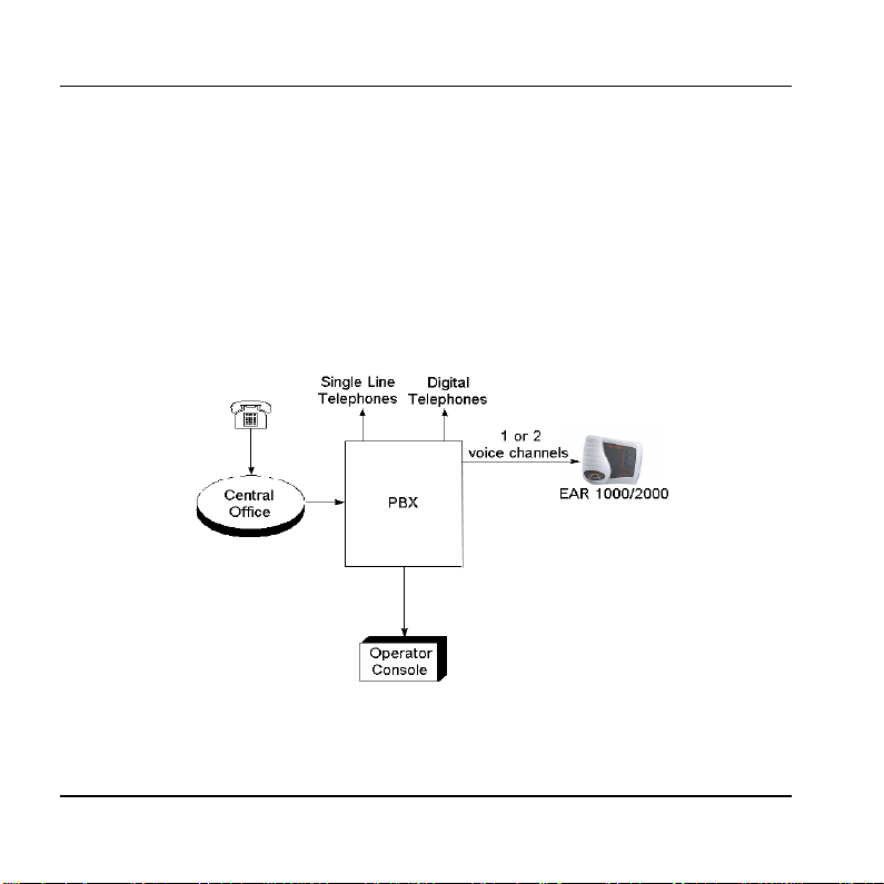
5. Call each EAR 1000/2000 line from any extension and verify the replay.
6. Program the EAR 1000/2000 according to your PBX type and required
applications (see Chapter 4).
Figure 3-4. System Installation
3-4 EAR 1000/2000 Installation and Programming Manual
Page 19

4. DTMF PROGRAMMING
The EAR 1000/2000 is programmed by telephone using DTMF tones.
For the EAR 2000, both lines can be programmed and recorded using DTMF
tones from one of the lines.
Note: A confirmation t one is heard every time a pro gramming command is
entered.
4.1 Entering and Exiting the P rogramming Mode
The EAR 1000/2000 does not handle calls when in the programming mode.
To enter the programming mode:
1. Call the Ear 1000/2000 Ext. from any touch-tone telephone.
2. Wait until the EAR 1000/2000 answers and plays the opening greeting or
plays a tone if no menu is recorded. Next, dial *900.
3. Dial the System Administrator’s password (the default password is 1234) to
enter the programming mode.
To exit the programming mode:
• Dial *900.
Note: When the programming mode is exited by dialing *900, the
EAR 1000/2000 plays the opening greeting. You can then test the
changes made to the system.
EAR 1000/2000 Installati on and Programming Manual 4-1
Page 20
DTMF Programming
4.2 DTMF Programming Commands
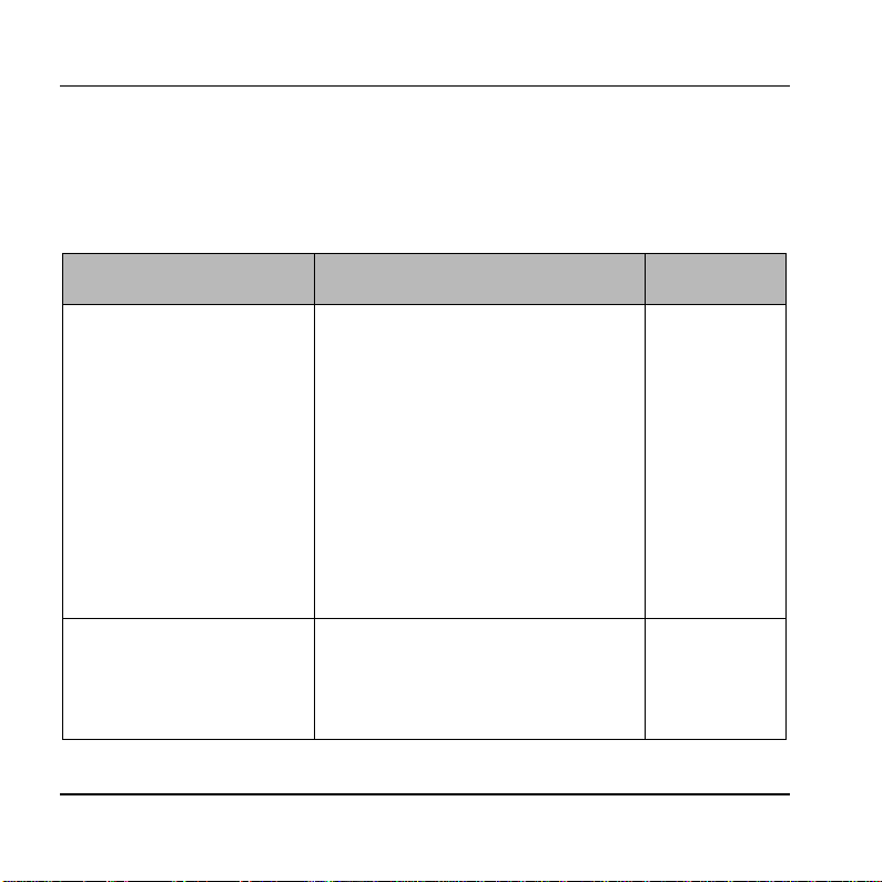
The following tables inclu de the DTMF commands available for the
EAR 1000/2000 system.
4.2.1 Script Messages
OPERATION COMMAND DEFAULT
Record a script message.
In the Ear 2000 it is
possible to define whether
to use different greetings for
lines 1 and 2 or to use the
same greetings for these
lines. Refer to command
*112 below.
Play a script message *101 + XX
4-2 EAR 1000/2000 Installation and Programming Manual
*100 + XX + Beep + Record + #
where
XX = 00 ; Day greeting
XX = 10 ; Night greeting
XX = 20 ; Holiday Mode greeting
XX = 22 ; Busy greeting
XX = 01 ; Transfer greeting
The following are only available for
the second line of EAR 2000
XX = 50 ; Day greeting
XX = 60 ; Night greeting
XX = 70 ; Holiday greeting
where
XX = Script message number (Same
as *100)
Page 21

Delete a script message
Deletes the message and
returns its parameters to
default values.
*102 + XX
where
XX = Script message number (Same
as *100)
DTMF Programming
Define the set of scripts to
be used when the second
line is called (see also
*100).
Note: For EAR 2000 only
*112 + X
where
X = 0 ; Uses scripts 00, 10, 20 for
both lines
X = 1 ; Uses scripts 00, 10, 20 for
0
line 1 and 50, 60, 70 for line 2
EAR 1000/2000 Installati on and Programming Manual 4-3
Page 22

DTMF Programming
4.2.2 PBX Parameters
OPERATION COMMAND DEFAULT
Number of digits in
extension.
*300 + X
where
3
X = Number of digits in extension
(1-6)
Number of rings before
line is answered.
*310 + X + Y
where
Line 1 Y = 1
Line 2 Y = 2
X = Line number (1 or 2)
Y = Number of rings (1-9)
Operator ID digit. When
this digit is dialed during
any script, the caller is
transferred to the operator.
*330 + X
where
X = Digit to be dialed by caller (0-
9)
0
(also see *360).
Non/Semi supervised
transfer
*350 + X + Y
where
All Ext. Non
Supervised
X = 1 ; All extensions except the
operator
X = 2 ; Operator extension only
Y = 0 ; Non supervised
Y = 1 ; Semi supervised
4-4 EAR 1000/2000 Installation and Programming Manual
Page 23

Operator extension
number
*360 + X + Ext. + #
where
X = 1 ; Day operator
X = 2 ; Night + Holiday operators
Ext. = Operator Ext. number
DTMF Programming
Ext. = 0
Flash Time *370 + XXX
600 ms
XXX – A 3 digit number (000-980)
in steps of 20 ms.
Busy, disconnect and
DTMF on/off time.
*371 + X + YYYY
where
X = 1 ; Busy off time
X = 2 ; Busy on time
X = 3 ; Disconnect off time
X = 4 ; Disconnect on time
YYYY = Cadence in ms (0100-
0500 ms
0500 ms
0240 ms
0240 ms
3000) in steps of 20ms
EAR 1000/2000 Installati on and Programming Manual 4-5
Page 24

DTMF Programming
PBX Transfer code and
Recall from Busy code.
*380 + X + Code + #
where
X = 1 ; Transfer code.
X = 2 ; Recall from busy code.
Code– respective DTMF code that
contains up to four digits including
0-9, #, * and A-D.
Special digits
*0 for Ext. *4 for # *7 for C
*1 for Pause *5 for A *8 for D
*2 for Flash *6 for B ** for *
4.2.3 Menus Handling
OPERATION COMMAND DEFAULT
Transfer call to an
extension at the end of the
script message or when the
caller dials a digit during a
script playback.
*120 + XX + B + Ext. + #
where
XX = Script message number (Same
as *100)
B = Digit to be dialed by caller or * at
the end of message playback.
Ext = Extension (contains up to six
digits)
Flash + Ext.
Flash
4-6 EAR 1000/2000 Installation and Programming Manual
Page 25

Transfer the call to an
operator at the end of the
script message.
Operator Ext. is defined by
command *360
*125 + XX + #
where
XX = Script message number (Same
as *100)
DTMF Programming
Disconnect the call at the
end of the script message.
*140 + XX + * + #
where
XX = Script message number (Same
as *100)
Direct transfer to an
extension. Enables the user
to directly dial an extension
during playback of a script
message
*170 + XX + first digit(s) + #
where
XX = Script message number (Same
as *100)
first digit(s) = First digit(s) of
extension. Up to four different digits
can be entered.
Reset Scripts to default
values. This command does
not delete the recorded
script messages.
EAR 1000/2000 Installati on and Programming Manual 4-7
*190 + XX + #
where
XX = Script message number (Same
as *100)
Page 26

DTMF Programming
Reset value in Scr ipt to
default values. This
command does not delete
the recorded script
messages.
*190 + XX + Y + #
where
XX = Script message number (Same
as *100)
Y = Specific digit value to reset in the
script.
4.2.4 Busy Menu Handling
OPERATION COMMAND DEFAULT
Return to the opening
greeting when caller dials
return digit during playback
of Busy script.
Place a call on hold.
Enables the call to remain
on hold. The caller is put on
hold for ten seconds before
trying to transfer the call
again.
*115 + B
where
B = Digit to be dialed by caller or * at
the end of greeting p layback
Note: This option is valid only for the
Busy menu (script 22).
*180 + B
where
B = Digit to be dialed by caller to put
the call on hold or * to put the call on
hold at the end of playback
Note: This option is valid only for the
Busy menu (script 22).
4-8 EAR 1000/2000 Installation and Programming Manual
Page 27

Blind Transfe r to a busy
p
extension. An immediate
attempt is made to transfer
the call to the extension
when the user dials the
transfer digit.
*185 + B
where
B = Blind transfer digit to be dialed
by the caller or * at the end of
greeting playback
Note: This option is valid only for
the Busy menu (script 22).
4.2.5 Advanced Features
OPERATION COMMAND DEFAULT
DTMF Programming
Time for End Of Message
action.
*105 + XX + Y + #
where
5
XX = Script message number (Same
as *100)
Y = 0-9 (sec)
Selecting DTMF code or
Call Progress tone
detection. This command is
valid in semi-supervised
transfer mode.
*220 + X
where
X = 0 ; Busy detect using Call
Progress tones.
X = 1 ; Busy detect using DTMF
Call Progress
codes.
Note: Option X=1 is valid only if the
orts assigned to the Ear 1000/2000
EAR 1000/2000 Installati on and Programming Manual 4-9
Page 28

DTMF Programming
in the PBX are defined as VM ports.
Defining the DTMF code
for the busy condition.
*221 + Code + #
where
Code – Each DTMF code can contain
up to four digits including 0-9.
To enter #, *, A-D use the following
DTMF combinations:
*4 for # *7 for C
*5 for A *8 for D
*6 for B ** for *
Note: This option is valid only if the
ports assigned to the Ear 1000/2000
in the PBX are defined as VM ports.
Disconnection code *333 + Code + #
# # #
where
Code = Disconnection code. Same as
Code table in *221
Greeting volume level *369 + X
5
where
X = Volume level (0-9)
9 is the highest volume level
4-10 EAR 1000/2000 Installati on and P rogramming Manual
Page 29

Busy signal cadence setup.
Setup of busy on/off-time
cadence.
*375 + XXXX + #
where
XXXX – Busy extension number.
Setting-up the Busy on/off-time
cadence by dialing the busy extension
number.
DTMF Programming
Change system
administrator passw ord.
*600 + * + Old passwor d + New
password + #
1234
Password must include 4 digits. Do
not use the digits * and #. This
password cannot be disabled.
Change operator’s
password. Used by the
operator to change the
opening greeting (Day,
Night, or Holiday).
*601 + * + Old passwor d + New
password + #
Password must include 4 digits. Do
not use the digits * and #. To disable
the password enter ‘0000’ as a new
1234
paaword.
Resetting the EAR
1000/2000.
Returns to default factory
*654 + * + XXXX + #
XXXX = System administrator
password.
settings and deletes all
script messages.
EAR 1000/2000 Installati on and P rogramming Manual 4-11
Page 30

Page 31

5. CHANGING THE OPENING GREETING
Changing the opening greeting between Day, Night and Holiday is performed in
one of the following methods:
1. Press the button on the EAR 1000/2000 front panel.
2. Call one of the EAR 1000/2000 extensions and during the opening greeting
dial:
*8 + XXXX + Y
where
XXXX = Operator password (default=1234)
Y = 0 ; Day Mode (default)
Y = 1 ; Night Mode
Y = 2 ; Holiday Mode
Note: Operator password can be skipped if canceled using command *601.
Set
EAR 1000/2000 Installati on and Programming Manual 5-1
Page 32

Page 33

6. PROGRAMMING EXAMPLE
The following paragraphs are examples for EAR 1000/2000 configuration. These
examples consider a PBX with a 3 digit extension size, an extension from 400 to
599, and Hook Flash value of 600ms.
Day Opening Greeting (Script 00)
“Welcome to ITS.
If you know the extension number you require, please dial it now.
For Help Desk dial 1. (Ext.440)
For Marketing dial 2. (Ext. 450)
For Management dial 3. (Ext. 460)
For the operator dial 0 or wait on the line.”
Night Opening Greeting (Script 10)
“Welcome to ITS.
If you know the extension number you need, please dial it now.
Our offices are currently close, our working hours are: Monday to Friday 8am5pm.
Thank you and goodbye.”
Extension Busy Greeting (Script 22)
“The extension required is busy.
To stay on hold dial 1.
For the operator dial 0 or wait.”
EAR 1000/2000 Installati on and Programming Manual 6-1
Page 34
Programming Example
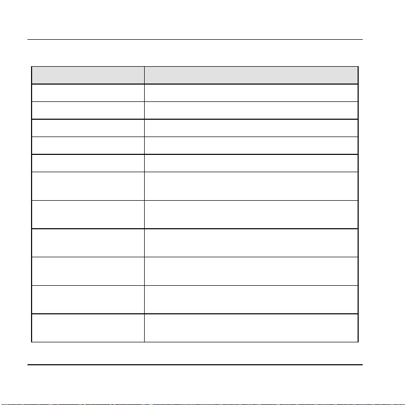
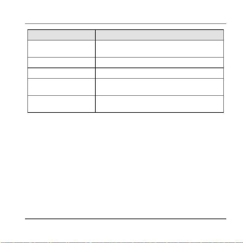
EAR 1000/2000 DTMF Commands
Command Meaning
* 900 1234 Enter programming mode
* 300 3 The Ext. numbers are 3 digits long
* 330 0 The digit for operator ID is 0
* 370 600 Hook Flash value is set to 600ms
* 360 1 400 # In Day mode operator Ext. is 400
* 170 00 4 5 # Enable direct call when either the digit 4 or 5 is dialed
during script message 00 (Day)
* 120 00 1 440 # Transfer the call to Ext. 440 when the digit 1 is dialed
during script message 00 (Day)
* 120 00 2 450 # Transfer the call to Ext. 450 when the digit 2 is dialed
during script message 00 (Day)
* 120 00 3 460 # Transfer the call to Ext. 460 when the digit 3 is dialed
during script message 00 (Day)
* 125 00 # At the end of script message 00 transfer call to
operator Ext.
* 170 10 4 5 # Enable direct call when either the digit 4 or 5 is dialed
during script message 10 (Night)
6-2 EAR 1000/ 2000 Installation and Programming Manual
Page 35
Programming Example
Command Meaning
* 140 10 * # At the end of script message 10 (Night) disconnect the
call
* 350 1 1 Set all Ext. except operator Ext. to be semi-supervised
* 350 2 0 Set operator Ext. to be non-supervised
* 180 1 # When an Ext. is busy, place the call on ho ld, if the
digit 1 is dialed
* 125 22 # At the end of script message 22 transfer the call to the
operator Ext.
EAR 1000/2000 Installati on and Programming Manual 6-3
Page 36

Page 37

SECTION II:
ADRA 1000/2000
Installation and Programming
Page 38

Page 39
7. OVERVIEW OF ADRA 1000/2000
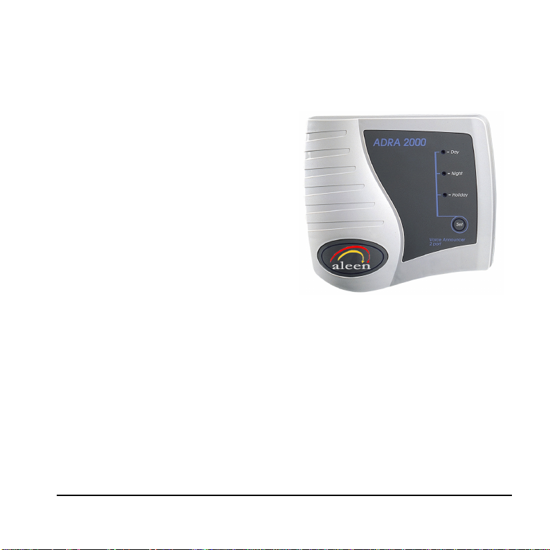
The ADRA 1000 is a one port AutoAnnouncer System. The ADRA
2000 is a two port Auto-Announcer
System. Both systems have up to 9
minutes of recording time.
The ADRA 1000/2000 can be
integrated with most types of PBX
through their analog ports, and can
be programmed by a touch-tone
telephone.
Figure 7-1. ADRA 2000 General View
7.1 Features and Services
The ADRA 1000/2000 has the following features:
• Opening Greetings: Day, Night, Holiday for each line.
• Call Transfer
The system administrator can program the ADRA 1000/2000 to transfer calls
to extensions in one of the following modes:
ADRA 1000/2000 Installati on and P rogramming Manual 7-1
Page 40

Overview of ADRA 1000/2000
− Non-supervised. The ADRA 1000/2000 transfers the call immediately,
without verifying the status of the extension.
−−−− Semi-supervised. The ADRA 1000/2000 checks for a busy signal before
transferring a call to an extensi on.
• Up to 9 minutes of recording time.
• High quality recording.
• Non-volatile memory (Flash memory).
• Adjustable flash time.
• Busy status detection using call progress tone or DTMF codes.
• Busy Extension playback message.
• Remote programming and recording.
• Simple operation and maintenance.
7-2 ADRA 1000/2000 Installation and Programming Manual
Page 41
8. DESCRIPTION AND INSTALLATION
8.1 Physical Description
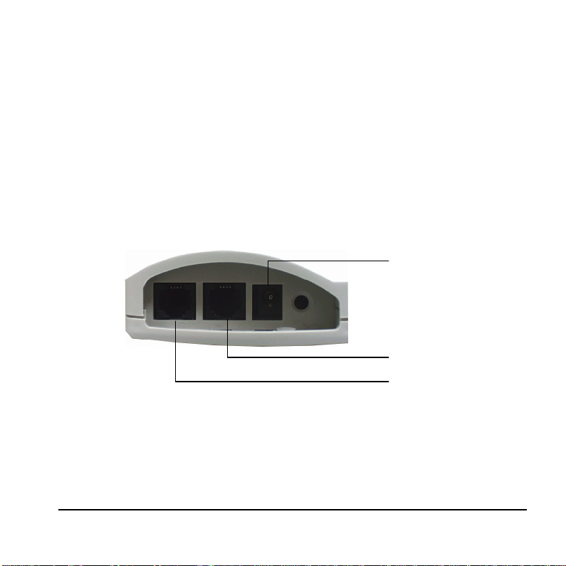
The functional components of the ADRA1000/2000 are located on its bottom
panel. The LEDs are on the front panel. The back panel has two indented holes
for wall mounting.
8.1.1 Bottom Panel
9VDC
Line 1
Line 2
ADRA 2000 Only
Figure 8-1. ADRA 1000/2000 Bottom P anel
ADRA 1000/2000 Installati on and P rogramming Manual 8-1
Page 42
Description and installation
The following description corresponds to the labels in Figure 8-1.
1. Power Supply
Connector
Connects the ADRA1000/2000 to the external powersupply.
2. 1/2 RJ-11 Sockets Connects the ADRA1000/2000 to PBX extensions.
8.1.2 Front Panel
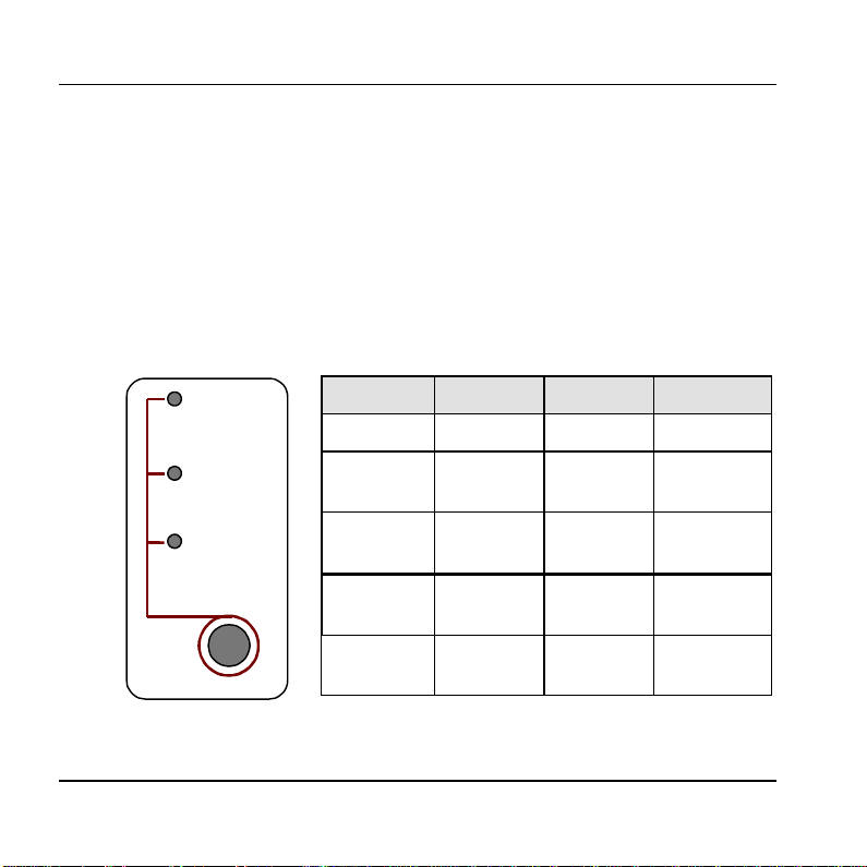
The following f i g ure a nd ta ble de sc r ibe the function of the three LE DS on the front
panel.
Figure 8-2. LEDs on
the Front Panel
- Day
- Night
- Holiday
Set
STATUS DAY NIGHT HOLIDAY
Day Mode On Off Off
Night
Off On Off
Mode
Holiday
Off Off On
Mode
System
1
Error
System
1
Error
Off Flashing Off
Flashing Flashing Flashing
1
Please contact your loc al deal er.
8-2 ADRA 1000/2000 Installation and Programming Manual
Page 43
Description and installation
8.2 Installation
The ADRA 1000/2000 is delivered completely assembled. It is designed for
mounting on a wall, close to the PBX.
8.2.1 Installing the ADRA 1000/2000
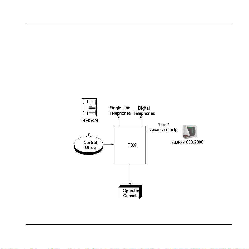
Figure 7-3 describes the system installation.
Figure 8-3. System Installation
ADRA 1000/2000 Installati on and P rogramming Manual 8-3
Page 44
Description and installation
t
t
To install the ADRA 1000/2000:
1. Mount the unit on a wall close to the PBX cabinet. Use the drill template to
place the two screws.
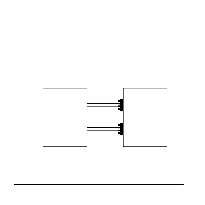
2. Connect the RJ-11 connector to the RJ-11 socket on the bottom panel of the
ADRA 1000/2000. Next, connect the other end of the cable to an analog
telephone line on the Main Distribution Frame (MDF) of the PBX (see Figure
8-4).
Main Distribution
Frame of the BPX
Line 1
Line 2
(ADRA 2000 Only)
Figure 8-4. Analog Line Connections
3. Plug the 9VDC adapter jack into the power supply connector on the bottom
panel of the ADRA 1000/2000.
8-4 ADRA 1000/2000 Installation and Programming Manual
ADRA 1000/2000
Bottom Panel
4-pin
RJ-11 socke
4-pin
RJ-11 socke
Page 45

Description and installation
3. Plug the 9VDC adapter into the main power supply outlet. The LEDs on the
front panel blink one after the other, then the LED indicating the status of the
ADRA 1000/2000 turns on.
4. Call each ADRA 1000/2000 line from any extension, and verify a
confirmation tone (short beep).
5. Program the ADRA 1000/2000 according to your PBX type an d the required
applications (see Chapt er 8).
ADRA 1000/2000 Installati on and P rogramming Manual 8-5
Page 46

Page 47

9. DTMF PROGRAMMING
The ADRA 1000/2000 is programmed by telephone using DTMF tones.
For the ADRA 2000, both lines can be programmed and recorded using DTMF
tones from one of the lines.
Note: A confirmation tone is heard every time a programming command is
entered.
9.1 Entering and Exiting the P rogramming Mode
The ADRA 1000/2000 does not handle calls when in programming mode.
To enter the programming mode:
1. Call the ADRA 1000/2000 Ext. from any touch-tone telephone.
2. Wait until the ADRA 1000/2000 answers and plays the opening greeting, or a
clear tone is heard (if no greeting is recorded). Next, dial *900.
3. Dial the System Administrator’s password (the default password is 1234) to
enter the programming mode.
To exit the programming mode:
• Dial *900.
ADRA 1000/2000 Installati on and P rogramming Manual 9-1
Page 48

DTMF Programming
9.2 DTMF Programming Commands
The following tables show the DTMF commands available for the
ADRA 1000/2000 system.
9.2.1 Script Messages
OPERATION COMMAND DEFAULT
To Record an Opening
Greeting.
In the ADRA 2000 it is
possible to define whether
to use different greetings for
lines 1 and 2 or to use the
same greetings for both
lines. Refer to command
*112 below.
Note: In case of rerecording, it’s
recommended to first delete
the existing message.
9-2 ADRA 1000/2000 Installation and Programming Manual
*100 + XX + Beep + Record + #
where:
XX = 00 ; Day greeting
XX = 10 ; Night greeting
XX = 20 ; Holiday greeting
XX = 22 ; Busy greeting
XX = 01 ; Transfer greeting
The following are only available for
the second line of ADRA 2000
XX = 50 ; Day greeting
XX = 60 ; Night greeting
XX = 70 ; Holiday greeting
No message is
recorded.
Page 49

DTMF Programming
Play an Opening Greeting. *101 + XX
where:
XX = Opening Greeting (same as
*100)
Delete an Opening
Greeting.
*102 + XX
where:
XX = Opening Greeting (same as
*100)
Define the set of greetings
to be used when the
second line is called.
Note: For ADRA 2000 only.
*112 + X
where:
X = 0 ; Uses greeting No. 00, 10, 20
for both lines.
X = 1 ; Uses greeting No. 00, 10, 20
for line 1 and 50, 60, 70 for line 2
First Set
ADRA 1000/2000 Installati on and P rogramming Manual 9-3
Page 50

DTMF Programming
9.2.2 PBX Parameters
OPERATION COMMAND DEFAULT
Number of rings before
line is answered.
*310 + X + Y
where:
Line 1 Y = 1
Line 2 Y = 2
X = Line number (1 or 2)
Y = Number of rings (1-9)
Non/Semi-supervised
transfer.
Note: When the required
extension is the Operator or
another extension.
*350 + X + Y
where:
X = 1 ; For all extensions except the
operator’s extension.
X = 2 ; Operator extension only
Y = 0 ; Non-supervised.
All Ext. Nonsupervised.
Y = 1 ; Semi-supervised.
Operator extension
number.
*360 + X + Ext. + #
where:
Ext. = 0
X = 1 ; Day operator
X = 2 ; Night + Holiday operators
Ext. = Operator Ext. number
9-4 ADRA 1000/2000 Installation and Programming Manual
Page 51

DTMF Programming
Flash Time. *370 + XXX
XXX – A 3 digit number (000-980)
in steps of 20 ms.
Busy and disconnec t
DTMF on/off time.
*371 + X + YYYY, where:
X = 1 ; Busy off time
X = 2 ; Busy on time
X = 3 ; Disconnect off time
X = 4 ; Disconnect on time
YYYY = Cadence in ms (0100-
3000) in steps of 20ms
PBX Transfer code and
Recall from Busy code.
*380 + X + Code + #
where:
X = 1 ; Transfer code.
X = 2 ; Recall from busy code.
Code– respective DTMF code that
contains up to four digits including
0-9, #, * and A-D.
Special digits
** for * *4 for # *1 for Pause
*5 for A *6 for B *2 for Flash
*7 for C *8 for D *0 for Ext.
600 ms
0500 ms
0500 ms
0240 ms
0240 ms
Flash + Ext.
Flash
ADRA 1000/2000 Installati on and P rogramming Manual 9-5
Page 52

DTMF Programming
9.2.3 Greeting Handling
OPERATION COMMAND DEFAULT
Transfer a call to an
extension at the end of the
Opening Greeting.
*120 + XX + * + Ext. + #
where:
XX = Opening Greeting number
(same as *100)
Ext = Extension (contains up to six
digits).
Transfer the call to the
operator’s ext. at the end
of the Opening Greeting.
Operator Ext. Is defined by
*125 + XX + #
where:
XX = Opening Greeting number
(same as *100)
command *360
Disconnect the call at the
end of the Opening
Greeting.
*140 + XX + * + #
where:
XX = Opening Greeting number
(same as *100)
Reset Opening Greeting to
default values. This
command does not delete
the recorded script
*190 + XX + #
where
XX = Opening Greeting number
(same as *100)
messages.
9-6 ADRA 1000/2000 Installation and Programming Manual
Page 53

DTMF Programming
9.2.4 Busy Menu Handling
OPERATION COMMAND DEFAULT
Place a call on hold at the
end of a BUSY greeting
message (script 22).
Enables the call to remain
on hold. The caller is put on
*180 + *
where:
* = Puts the call on hold at the end of
a Busy greeting message
hold for 10 seconds before
trying to transfer the call
again.
Blind Transfe r to a busy
extension. An immediate
attempt is made to transfer
the call to the extension.
*185 + *
Blind transfer at the end of a Busy
greeting message (script 22).
ADRA 1000/2000 Installati on and P rogramming Manual 9-7
Page 54

DTMF Programming
9.2.5 Advanced Features
OPERATION COMMAND DEFAULT
Selecting DTMF code or
Call Progress tone
detection.
*220 + X
where:
X = 0 ; Busy detect using Call
Call Progress
Progress tones.
X = 1 ; Busy detect using DTMF
codes.
Note: This option is valid only if the
ports assigned to the ADRA
1000/2000 in the PBX are defined as
VM ports.
Defining the DTMF code
for the busy condition.
*221 + Code + #
where:
Code – Each DTMF code can contain
up to four digits including 0-9, #, *
and A-D.
Special digits
** for * *4 for #
*5 for A *6 for B
*7 for C *8 for D
Note: This option is valid only if the
ports assigned to the ADRA1000/2000 in the PBX are defined as
VM ports.
9-8 ADRA 1000/2000 Installation and Programming Manual
Page 55

DTMF Programming
Disconnection code. *333 + Code + #
where:
Code = Disconnection code. Same as
Code table in *221
Greeting volume level. *369 + X
where:
X = Volume level (0-9)
9 is the highest volume level
Busy signal cadence learn.
Checks the busy signal by
dialing the busy extension
*375 + XXXX + #
where:
XXXX – Busy extension number
number and implements the
recorded values.
Change system
administrator passw ord.
*600 + * + Old passwor d + New
password + #
Password must include 4 digits. This
password cannot be disabled.
Warning: Do not use the * or # keys.
# # #
5
1234
ADRA 1000/2000 Installati on and P rogramming Manual 9-9
Page 56

DTMF Programming
Change operator’s
password. Used by the
operator to change the Day,
Night, and Holiday
greetings.
Resetting the ADRA
1000/2000.
Returns to default factory
settings and deletes all
opening greetings.
*601 + * + Old passwor d + New
password + #
Password must include 4 digits. To
disable the password enter ‘0000’.
Warning: Do not use the * or # keys.
*654 + * + XXXX + #
XXXX = System administrator
password.
1234
9-10 ADRA 1000/2000 Installati on and P rogramming Manual
Page 57

10. CHANGING THE OPENING GREETING
Changing the opening greeting between Day, Night, and Holiday, is possible in
one of the following methods:
1. Using the button on the unit’s front panel.
2. Dialing to one of the unit’s extensions and when the current greeting is played
using the following DTMF code:
*8 + XXXX + Y
where:
XXXX = Operator password (default=1234).
Y = 0 ; Day greeting (default).
Y = 1 ; Night greeting.
Y = 2 ; Holiday greeting.
set
ADRA 1000/2000 Installation and Programming Manual 10-1
Page 58

Page 59

APPENDIX A EAR/ADRA SPECIFICATIONS
The following are the EAR 1000/2000 and ADRA 1000/2000 specifications:
DC Power Supply
Line Voltage
DC Leakage Current
On-hook Insulation Resistance between
Line Terminal and
the Ground
Ring Capacitor
On-hook Impedance
Ring Detect
DC Resistance (off-hook)
Impedance (off-hook)
Imbalance Ratio
Return Loss
Current during Break
DTMF Transmission:
Frequency Tolerance
Frequency Level (High Group)
Frequency Level (Low Group)
Inter-digit Pause in Tone Dialing
Recording Time
EAR/ADRA Install ation and Programming Manual A-1
9 Vdc/800 mA
24 to 72 Vdc
< 10 µA
0 to 100 Vdc > 5 MΩ
100 to 200 Vdc > 30 KΩ
500 Vac/50 Hz > 20 KΩ
100 Vac/25 Hz > 100 KΩ
0.47 µF ± 10%
@ 50 Vdc, 40 Vac/25 Hz > 3000 Ω
27 to 100 Vac/16 to 60 Hz
24 to 66 Vdc @ 20 to 100 mA
300 to 3400 Hz 500 to 700 Ω
300 to 3400 Hz > 46 db
300 to 3400 Hz > 18 db
< 700 µA
+1.5%
-6 to -8 dBm
-8 to -10 dBm
70 to 80 ms
9 Minutes
Page 60

 Loading...