

Aleco Clear-FlexII with Loop Strip Mounting System User Manual
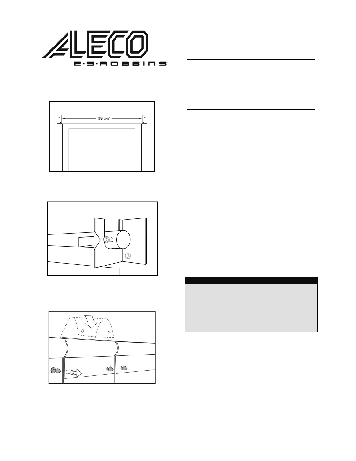
Di agram 1
Bar Placement
Diagram 2
Attac h Bar
Clear-Flex ® II
Installation Instructions
Us ing HTP Bu lle t/Lo op Ins t a lla tion Sy s t e m
TOOLS NEE D ED
• Ratchet or Wren ch
• Drill
• Step Stool or Ladd er
• Utility Knife to Cut Strips
1. Cente r and at tach left and right mounting
bra c kets with ¼” lag screws on the in sid e
wall of wal k -i n above do or openi ng 39
apart on a lev e l line. Attach lag scre w in
bottom hole o n ly on each b r acket (Dia gram
1).
2. Place mo unti ng bar in b r a c kets a nd in stall
¼” lag screw throug h both the mounting bar
and bracket o n both sid e s and tighten al l
scre ws (Di agram 2).
3. Attach strip s by folding stri p over ba r fro m
behin d and p u shi ng HTP Bullet (sh ade d
gray) th roug h holes (Dia gram 3).
3/ 8
”
Diagram 3
Attac h Strips
4.
Once all of the door strip s have bee n
attache d , the strip s can be trimmed to le ave
¼” of clea ran c e from the fl oor surfa c e. Your
PVC door stri ps may be tri mmed by usi ng a
comm on utility knife to score and then be
torn by hand
.
Parts List
(1) L e ft Moun ting Bracket
(1) Right Mou n ting Bra c ket
(1) Mo unting Bar
(4) ¼ ” Lag Screws
(9) 6 ” x .060 Clea r Flex® II Strips
or
(6) 8 ” x .080 Clea r Flex® II Strips
FOR ANY QUESTIONS OR COMME NTS, PLE ASE CO NTACT AN ALECO REPRESENTATIV E
2720 E . Av alon Ave. Mu scle Shoal s, AL 35661 ● Phone (256) 248-2 402 or toll free 1-8 00-633- 3120
Fax : 1-800-750 -96 16 ● email : in fo@ a leco . com ● w eb: www . aleco.com
P/N 477097
(Rev 6/29/05)
 Loading...