

Aleco Clear-Flex II User Manual
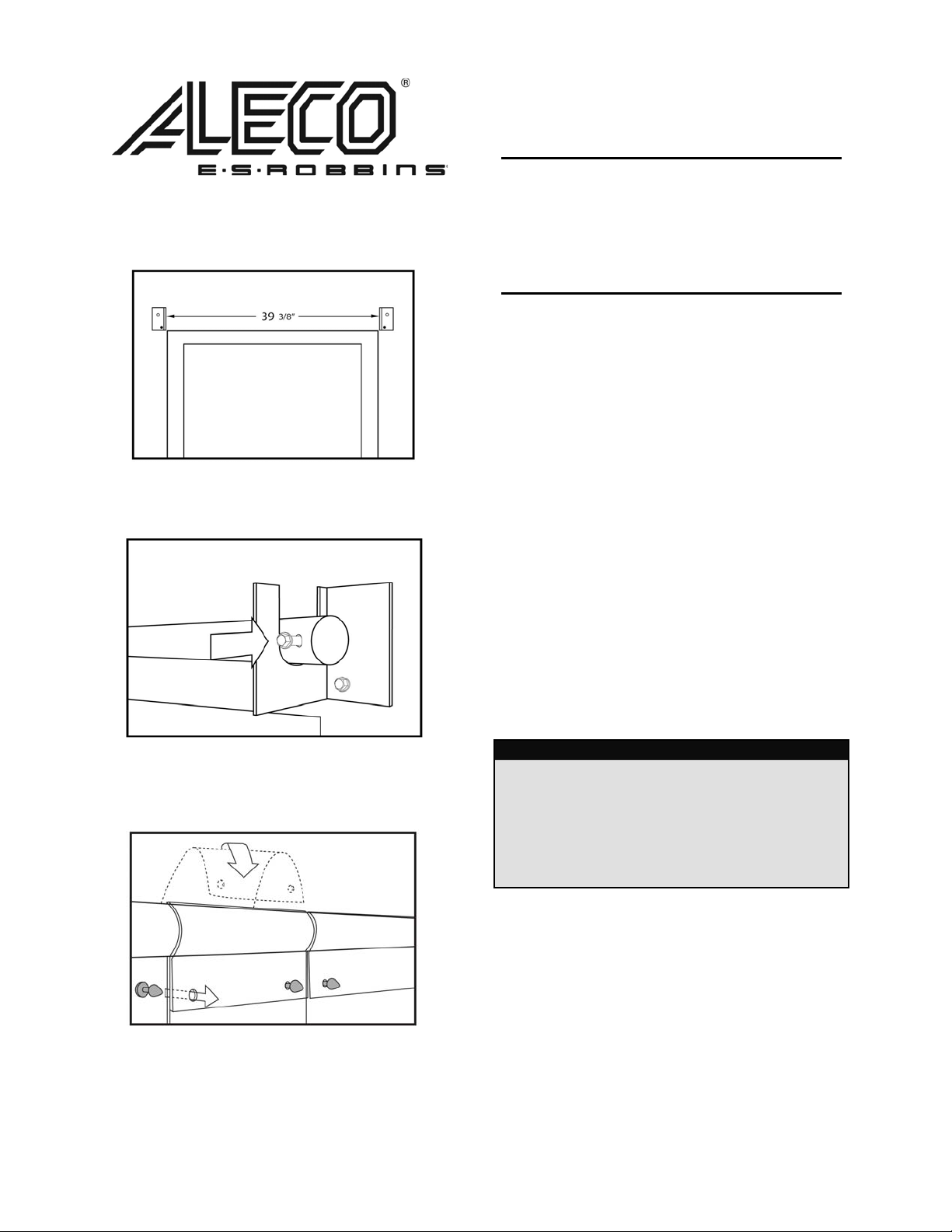
Diagram 1
Placement
Bar
Diagram
Attac
2
h Bar
Clear-Flex® II
Installation Instructions
Using HTP Bullet/Loop Installation System
TOOLS NEEDED
• Ratchet or Wrench
• Drill
• Step Stool or Ladder
• Utility Knife to Cut Strips
1. Center and attach left and right mounting
brackets with ¼” lag screws on the inside
of walk-in above door opening 39
wall
apart
on a level line. Attach lag screw in
bottom
hole only on each bracket (Diagram
1).
2. Place mounting bar in brackets and install
¼”
lag screw through both the mounting bar
and
bracket on both sides and tighten all
ews (Diagram 2).
scr
3. Attach strips by folding strip over bar from
nd and pushing HTP Bullet (shaded
behi
gray)
through holes (Diagram 3).
3/8
”
Diagram
h Strips
Attac
3
4.
Once all of the door strips have been
attached, the strips can be trimmed to leave
¼”
of clearance from the floor surface. Your
door strips may be trimmed by using a
PVC
common
torn
utility knife to score and then be
by hand
.
Parts List
(1) Left Mounting Bracket
(1) Right Mounting Bracket
(1) Mounting Bar
(4) ¼” Lag Screws
(9) 6” x .060 Clear Flex II Strips
or
(6) 8” x .080 Clear Flex II Strips
FOR ANY QUESTIONS OR COMMENTS, PLEASE CONTACT AN ALECO REPRESENTATIVE
2720
E. Avalon Ave. Muscle Shoals, AL 35661 ● Phone (256) 248-2402 or toll free 1-800-633-3120
Fa
x: 1-800-750-9616 ● email: info@aleco.com ● web: www.aleco.com
P/
N 477097
(Re
v 6/29/05)
 Loading...