

Aleco Air Curtains User Manual
JetStream®Air Curtain
Part Number A B C D E F G H I J
11
7/16
"
22"
11
7/16
"
22"
10
"
17"
60"
22
"
10
"
22
"
Part Number A B C D E F G H I J
11
7/16
"
22"
11
7/16
"
22"
10
5/8
"
17"
60"
22
"
10
"
22
"
Installation Instructions
CAUTION: READ CAREFULLY
!
Do not install unit outdoors
Do not install unit where it can get wet or
near excessive steam or corrosive gases
Use unit at voltage and frequency specified
Never use harsh chemicals to clean the unit
TOOLS NEEDED:
Pen or Pencil
Drill
Phillips Screwdriver
Tape Measure
Ladder
IMPORTANT - PLEASE READ!
If the air curtain is dropped on its side during shipment, the blower wheels may come out of the side bushings. BEFORE
OPERATING be sure to check the blower wheels on the left and right side of the unit! Follow these steps to correct the
problem:
1) Unscrew and remove the intake grill on the front and the round end-plate on the side of the unit. 2) Loosen the set screw that holds the blower wheel
on the motor shaft. 3) Remove the rubber bushing from the round end-plate and push onto the round metal bearing that is attached to the end of the
blower wheel. Make sure the rubber bushing is bottomed out on the bearing. 4) Reattach the round end-plate to the unit and then slide the blower wheel
toward the end-plate, pushing the rubber bushing back into the plate. 5) Tighten the set screw to hold the blower wheel on the motor shaft. Reattach the
intake grill.
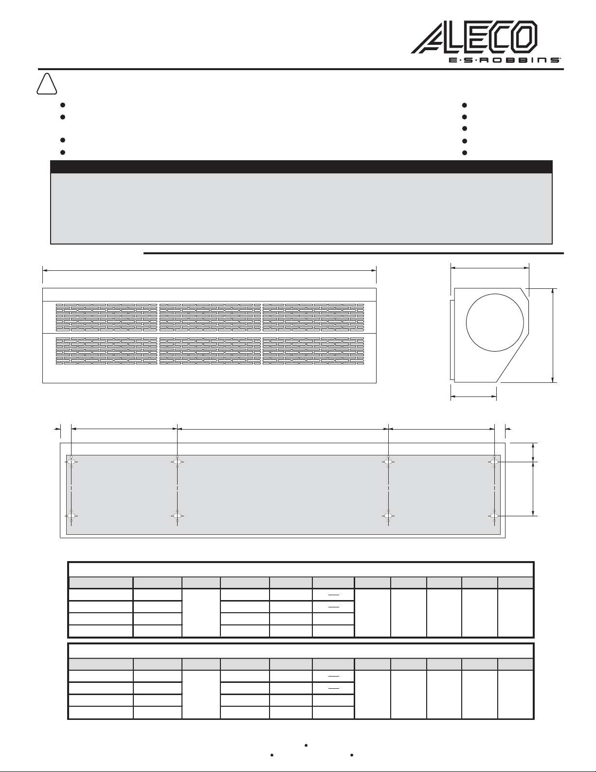
PART DIMENSIONS
A
I
H
FRONT
B C D E B
BACK (
mounting plate is shaded portion)
ENAMEL COATED AIR CURTAIN DIMENSIONS
475009
475010
475012
475015
36"
42"
48"
3/16
1
STAINLESS STEEL AIR CURTAIN DIMENSIONS
"
17"
7/16
5/8
5/8
7/16
2" 5
13/16
"10
1/8
"
J
SIDE
F
G
1/2
8
"5
1/4
"
475018
475021
475024
475027
P/N 477258
0511
36"
42"
48"
2720 E. Avalon Ave. Muscle Shoals AL, 35661 Phone (256) 248-2402 or toll free 1-800-633-3120
3/16
"
1
FOR ANY QUESTIONS OR COMMENTS, PLEASE CONTACT AN ALECO REPRESENTATIVE
Fax: 1-800-750-9616 email: info@aleco.com web: www.aleco.com
17"
7/16
5/8
7/16
2" 5
13/16
"10
1/8
1/2
"
8
"5
1/4
"
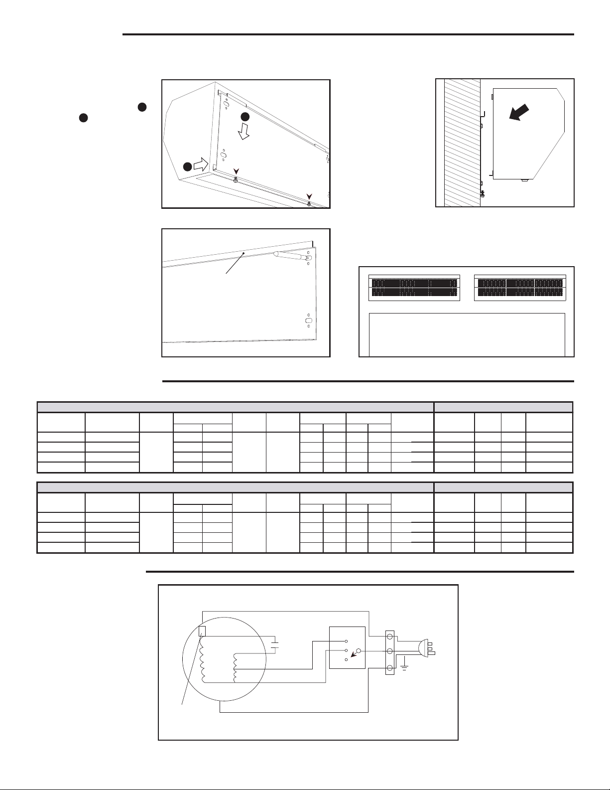
INSTALLATION
475009 36" x 8.5" x 10" 350 31
3.00
3.74
0.35 1400 0.47
0.67
0.80
0.90
475010 42" x 8.5" x 10" 500 33 0.50 1400
475012 48" x 8.5" x 10" 600 37
5.25
0.60 1400
475015 60" x 8.5" x 10" 670
345
495
595
665 44
60
60
61
62
58
58
59
60
5.75
0.67 1400
ENAMEL COATED MODEL TECHNICAL SPECIFICATIONS
MOTOR SPECIFICATIONS
Horsepower
Part Number
Unit Size
(L x W x H)
475018 36" x 8.5" x 10" 500 1210 69 43
475021 42" x 8.5" x 10" 650 1355 71 48
475024 48" x 8.5" x 10" 650 1860 73 53
475027 60" x 8.5" x 10" 800
495
645
645
795 2325
990
1100
1515
1890 75
67
69
71
73 62
STAINLESS STEEL MODEL TECHNICAL SPECIFICATIONS
MOTOR SPECIFICATIONS
Horsepower
Part Number
Unit Size
(L x W x H)
Volt/Freq
(V/Hz)
NOTE: For freezer applications, mount unit to OUTSIDE of freezer to prevent motor and fans from freezing.
Step 1 Remove mounting
plate from unit by loosening
screws and pulling it back [ ]
and down [ ].
2
1
NOTE: Keep in mind when
installing, unit is designed
for indoor use only.
Step 2 Using the mounting
plate as a template, mark and
drill the holes. The distance
between the bottom of the plate
and the top of the door should
not exceed 3 in.
Step 3 Mount the plate
using fasteners suitable for
the application, making sure
plate is snug against the wall.
UNIT SPECIFICATIONS
Step 4 Attach
unit to mounting
plate and tighten
2
screws on bottom.
Step 5 Plug unit
into wall outlet using
1
Figure A
LIPPED EDGE
Figure B Figure D
the furnished 5 foot
cord located on top
center of unit or wire
unit according to local
code.
NOTE: When entrance is wider than unit, it is recommended
to install units side by side, approximately 1” - 2” apart.
Figure C
ELECTRICAL GUIDE
Volt/Freq
(V/Hz)
110/60
110~
120/60
Input Power (W)
Input Power (W)
Hi Lo
BLUE (RED, BLACK, GREEN)
Avg. Air
Velocity
Avg. Air
Velocity
Max Air
Velocity
2560 FPM2260 FPM
Max Air
Velocity
3150 FPM2850 FPM
YELLOW (BROWN)
C
YELLOW (BROWN)
GREY
WHITE
Air Vol. (cfm) Noise (dB) Net Weight
790
1135
1385
LO
HI
Hi Lo
K
Hi LoHi Lo
890 740
950
1365
1660
Air Vol. (cfm) Noise (dB) Net Weight
Hi Lo Hi Lo
(lbs)
(lbs)
N
L
OFF
Current
(A)
Current
(A)
5.40
5.40
6.80
Power
(KW)
Power
(KW)
0.503.74
0.65
0.65
0.80
RPM
RPM
1600
1600
1600
1600
0.67
0.87
0.87
1.00
TEMP.
PROTECTOR
Be sure to comply with all NEC guidlines regarding electrical wiring and connections.
YELLOW-GREEN
 Loading...