

Page 1

OcuScan® RxP
Measuring System
OPERATORʼS MANUAL
Manufacturer: EU Authorized Representative:
Alcon Laboratories, Inc. Alcon Laboratories (U.K.) Ltd.
6201 South Freeway Boundary Way, Hemel Hempstead
Fort Worth, Texas 76134-2099 Hertfordshire, HP2 7UD England
U.S.A.
Produced By:
Alcon Laboratories, Inc.
15800 Alton Parkway
Irvine, California 92618-3818
U.S.A.
Telephone: 949/753-1393
800/832-7827
FAX: 949/753-6614
8065750127 F, ASSEMBLY
905-6850-001 E, TEXT ONLY
©
2003-2005 Alcon, Inc.
Page 2

OcuScan
®
RxP Measuring System
OcuScan® RxP Operator's Manual
8065750127
MANUAL REVISION RECORD
DATE REVISION ECN NUMBER & REVISED PAGE NUMBERS
June 2003 A ECN 20033093 - Initial release of operator's manual.
Dec. 2003 B ECN 20033945 - Updated information for the Patient Viewer tem
plate along with other miscellaneous changes. Changed pages
include: i(title) - iii, vi, 1.2, 1.4, 1.8, 2.4, 3.1, 3.2, 3.38, 3.39,
3.42 - 3.48, 4.1, 5.2. 6.1.
Jan. 2004 C ECN 20042012 - No changes to text; clerical change to assembly
drawing.
Oct. 2004 D ECN 20043577 - Update EMC statement. Changed pages include:
i (title) - viii, 1.6 - 1.22, 7.1 - 7.2.
June 2005 E ECN 20050660 - Updated manual with new information for instru
-
ment disposal (WEEE). Changes to pages i, ii, 1-10, 1-14, and 7-1.
Nov. 2005 F ECN 20051333 - Updated manual with new information for software
version 1.12. Changes made to over 90% of manual.
* Registered in the U.S. Patent and Trademark Office.
Windows is a Reg. TM of Microsoft Corporation.
ActiveSync is a Reg. TM of Microsoft Corporation.
ii 8065750127
Page 3

OcuScan
®
RxP Measuring System
TABLE OF CONTENTS
SECTION ONE - GENERAL INFORMATION PAGE #
The OcuScan® RxP Measuring System . . . . . . . . . . . . . . . . . . . . . . . . . . . . . . . . . . . . . . . . . . . . . . .1.1
Quick Start . . . . . . . . . . . . . . . . . . . . . . . . . . . . . . . . . . . . . . . . . . . . . . . . . . . . . . . . . . . . . . . . . . . . .1.2
Installation Instructions . . . . . . . . . . . . . . . . . . . . . . . . . . . . . . . . . . . . . . . . . . . . . . . . . . . . . . . . . . . .1.3
Installing Optional Software and Updating System Software . . . . . . . . . . . . . . . . . . . . . . . . . . . . . .1.4
Notes, Cautions, and Warnings . . . . . . . . . . . . . . . . . . . . . . . . . . . . . . . . . . . . . . . . . . . . . . . . . . . . . .1.6
EMC Statement . . . . . . . . . . . . . . . . . . . . . . . . . . . . . . . . . . . . . . . . . . . . . . . . . . . . . . . . . . . . . . . . . .1.7
Universal Precautions . . . . . . . . . . . . . . . . . . . . . . . . . . . . . . . . . . . . . . . . . . . . . . . . . . . . . . . . . . . .1.11
Underwriter's Laboratories . . . . . . . . . . . . . . . . . . . . . . . . . . . . . . . . . . . . . . . . . . . . . . . . . . . . . . . .1.11
Accessory Equipment . . . . . . . . . . . . . . . . . . . . . . . . . . . . . . . . . . . . . . . . . . . . . . . . . . . . . . . . . . . .1.11
Environmental Issues . . . . . . . . . . . . . . . . . . . . . . . . . . . . . . . . . . . . . . . . . . . . . . . . . . . . . . . . . . . .1.11
User Information - Environmental Consideration . . . . . . . . . . . . . . . . . . . . . . . . . . . . . . . . . . . . . .1.11
Safety Requirements . . . . . . . . . . . . . . . . . . . . . . . . . . . . . . . . . . . . . . . . . . . . . . . . . . . . . . . . . . . . .1.12
Product Service . . . . . . . . . . . . . . . . . . . . . . . . . . . . . . . . . . . . . . . . . . . . . . . . . . . . . . . . . . . . . . . . .1.13
Limited Warranty . . . . . . . . . . . . . . . . . . . . . . . . . . . . . . . . . . . . . . . . . . . . . . . . . . . . . . . . . . . . . . .1.13
IOL Calculation Formulas . . . . . . . . . . . . . . . . . . . . . . . . . . . . . . . . . . . . . . . . . . . . . . . . . . . . . . . .1.16
SECTION TWO - DESCRIPTION
General Description . . . . . . . . . . . . . . . . . . . . . . . . . . . . . . . . . . . . . . . . . . . . . . . . . . . . . . . . . . . . . .2.1
Front Panel . . . . . . . . . . . . . . . . . . . . . . . . . . . . . . . . . . . . . . . . . . . . . . . . . . . . . . . . . . . . . . . . . . . . .2.1
Rear Panel . . . . . . . . . . . . . . . . . . . . . . . . . . . . . . . . . . . . . . . . . . . . . . . . . . . . . . . . . . . . . . . . . . . . . .2.3
Flash Card Slot . . . . . . . . . . . . . . . . . . . . . . . . . . . . . . . . . . . . . . . . . . . . . . . . . . . . . . . . . . . . . . . . . .2.4
Eye Model . . . . . . . . . . . . . . . . . . . . . . . . . . . . . . . . . . . . . . . . . . . . . . . . . . . . . . . . . . . . . . . . . . . . . .2.4
Footswitch . . . . . . . . . . . . . . . . . . . . . . . . . . . . . . . . . . . . . . . . . . . . . . . . . . . . . . . . . . . . . . . . . . . . . .2.5
Probes and Probe Holders . . . . . . . . . . . . . . . . . . . . . . . . . . . . . . . . . . . . . . . . . . . . . . . . . . . . . . . . . .2.7
External Power Supply . . . . . . . . . . . . . . . . . . . . . . . . . . . . . . . . . . . . . . . . . . . . . . . . . . . . . . . . . . . .2.8
Keyboards . . . . . . . . . . . . . . . . . . . . . . . . . . . . . . . . . . . . . . . . . . . . . . . . . . . . . . . . . . . . . . . . . . . . . .2.9
SECTION THREE - OPERATING INSTRUCTIONS
Introduction . . . . . . . . . . . . . . . . . . . . . . . . . . . . . . . . . . . . . . . . . . . . . . . . . . . . . . . . . . . . . . . . . . . . .3.1
System Power-Up . . . . . . . . . . . . . . . . . . . . . . . . . . . . . . . . . . . . . . . . . . . . . . . . . . . . . . . . . . . . . . . .3.2
System Reset . . . . . . . . . . . . . . . . . . . . . . . . . . . . . . . . . . . . . . . . . . . . . . . . . . . . . . . . . . . . . . . . . . . .3.2
The Menu Screen . . . . . . . . . . . . . . . . . . . . . . . . . . . . . . . . . . . . . . . . . . . . . . . . . . . . . . . . . . . . . . . .3.3
Using the Touch Screen . . . . . . . . . . . . . . . . . . . . . . . . . . . . . . . . . . . . . . . . . . . . . . . . . . . . . . . . . . .3.3
System Setup . . . . . . . . . . . . . . . . . . . . . . . . . . . . . . . . . . . . . . . . . . . . . . . . . . . . . . . . . . . . . . . . . . . .3.4
Patient Records Screen . . . . . . . . . . . . . . . . . . . . . . . . . . . . . . . . . . . . . . . . . . . . . . . . . . . . . . . . . . . .3.9
Probe Check . . . . . . . . . . . . . . . . . . . . . . . . . . . . . . . . . . . . . . . . . . . . . . . . . . . . . . . . . . . . . . . . . . .3.11
BIOMETRY . . . . . . . . . . . . . . . . . . . . . . . . . . . . . . . . . . . . . . . . . . . . . . . . . . . . . . . . . . . . . . . . . . .3.13
Setting up the Biometry Presets . . . . . . . . . . . . . . . . . . . . . . . . . . . . . . . . . . . . . . . . . . . . . . . . . . . .3.13
Settings . . . . . . . . . . . . . . . . . . . . . . . . . . . . . . . . . . . . . . . . . . . . . . . . . . . . . . . . . . . . . . . . .3.14
Phakic Eye Velocities . . . . . . . . . . . . . . . . . . . . . . . . . . . . . . . . . . . . . . . . . . . . . . . . . . . . . .3.15
Acquisition Speed . . . . . . . . . . . . . . . . . . . . . . . . . . . . . . . . . . . . . . . . . . . . . . . . . . . . . . . . .3.16
Validation . . . . . . . . . . . . . . . . . . . . . . . . . . . . . . . . . . . . . . . . . . . . . . . . . . . . . . . . . . . . . . .3.16
Audio Feedback . . . . . . . . . . . . . . . . . . . . . . . . . . . . . . . . . . . . . . . . . . . . . . . . . . . . . . . . . .3.17
Keratometer Index . . . . . . . . . . . . . . . . . . . . . . . . . . . . . . . . . . . . . . . . . . . . . . . . . . . . . . . .3.17
Sequence . . . . . . . . . . . . . . . . . . . . . . . . . . . . . . . . . . . . . . . . . . . . . . . . . . . . . . . . . . . . . . . .3.18
Pseudo and Phakic IOL Defaults . . . . . . . . . . . . . . . . . . . . . . . . . . . . . . . . . . . . . . . . . . . . .3.18
Lens Constants . . . . . . . . . . . . . . . . . . . . . . . . . . . . . . . . . . . . . . . . . . . . . . . . . . . . . . . . . . .3.18
Lens Constant Update Screen . . . . . . . . . . . . . . . . . . . . . . . . . . . . . . . . . . . . . . . . . . . . . . . .3.19
8065750127 iii
Page 4

OcuScan
®
RxP Measuring System
SECTION THREE - OPERATING INSTRUCTIONS (continued) PAGE #
Patient Setup for Biometry . . . . . . . . . . . . . . . . . . . . . . . . . . . . . . . . . . . . . . . . . . . . . . . . . . . . . . . .3.22
OD/Right Eye and OS/Left Eye . . . . . . . . . . . . . . . . . . . . . . . . . . . . . . . . . . . . . . . . . . . . . .3.24
K Values Before Refractive Surgery . . . . . . . . . . . . . . . . . . . . . . . . . . . . . . . . . . . . . . . . . . .3.25
Refractive Error Before Refractive Surgery . . . . . . . . . . . . . . . . . . . . . . . . . . . . . . . . . . . . .3.25
Refractive Error After Refractive Surgery . . . . . . . . . . . . . . . . . . . . . . . . . . . . . . . . . . . . . .3.25
Adjusted K . . . . . . . . . . . . . . . . . . . . . . . . . . . . . . . . . . . . . . . . . . . . . . . . . . . . . . . . . . . . . .3.25
Biometry Scans . . . . . . . . . . . . . . . . . . . . . . . . . . . . . . . . . . . . . . . . . . . . . . . . . . . . . . . . . . . . . . . . .3.27
Biometry Measurements in Manual Mode . . . . . . . . . . . . . . . . . . . . . . . . . . . . . . . . . . . . . .3.28
Editing the Gate Positions . . . . . . . . . . . . . . . . . . . . . . . . . . . . . . . . . . . . . . . . . . . . . . . . . . .3.30
Biometry Measurements in Automatic (Auto) Mode . . . . . . . . . . . . . . . . . . . . . . . . . . . . . .3.32
Biometry Scans in Super-Automatic (S-Auto) Mode . . . . . . . . . . . . . . . . . . . . . . . . . . . . . .3.33
Biometry Details Screen . . . . . . . . . . . . . . . . . . . . . . . . . . . . . . . . . . . . . . . . . . . . . . . . . . . .3.34
IOL Calculation Screen . . . . . . . . . . . . . . . . . . . . . . . . . . . . . . . . . . . . . . . . . . . . . . . . . . . . .3.35
Comparison Screen . . . . . . . . . . . . . . . . . . . . . . . . . . . . . . . . . . . . . . . . . . . . . . . . . . . . . . . .3.36
Formula Configuration Screen . . . . . . . . . . . . . . . . . . . . . . . . . . . . . . . . . . . . . . . . . . . . . . .3.37
PACHYMETRY
. . . . . . . . . . . . . . . . . . . . . . . . . . . . . . . . . . . . . . . . . . . . . . . . . . . . . . . . . . . . . . . .3.39
Setting Up the Pachymetry Presets . . . . . . . . . . . . . . . . . . . . . . . . . . . . . . . . . . . . . . . . . . . . . . . . . .3.39
Settings . . . . . . . . . . . . . . . . . . . . . . . . . . . . . . . . . . . . . . . . . . . . . . . . . . . . . . . . . . . . . . . . .3.40
The Single-Point Screen . . . . . . . . . . . . . . . . . . . . . . . . . . . . . . . . . . . . . . . . . . . . . . . . . . . .3.41
Map 1/Map 2 . . . . . . . . . . . . . . . . . . . . . . . . . . . . . . . . . . . . . . . . . . . . . . . . . . . . . . . . . . . . .3.41
The Lasik Screen . . . . . . . . . . . . . . . . . . . . . . . . . . . . . . . . . . . . . . . . . . . . . . . . . . . . . . . . . .3.41
Pachymetry Scans . . . . . . . . . . . . . . . . . . . . . . . . . . . . . . . . . . . . . . . . . . . . . . . . . . . . . . . . . . . . . . .3.43
Pachymetry Patient Setup . . . . . . . . . . . . . . . . . . . . . . . . . . . . . . . . . . . . . . . . . . . . . . . . . .3.43
Pachymetry Scans in Manual Mode . . . . . . . . . . . . . . . . . . . . . . . . . . . . . . . . . . . . . . . . . . .3.46
Pachymetry Scans in Auto Mode . . . . . . . . . . . . . . . . . . . . . . . . . . . . . . . . . . . . . . . . . . . . .3.46
Pachymetry Scans in S-Auto Mode . . . . . . . . . . . . . . . . . . . . . . . . . . . . . . . . . . . . . . . . . . .3.47
Pachymetry Scans using the Single Point Screen . . . . . . . . . . . . . . . . . . . . . . . . . . . . . . . . .3.47
Pachymetry Scans using the Map Screens . . . . . . . . . . . . . . . . . . . . . . . . . . . . . . . . . . . . . .3.48
Pachymetry Scans using the Lasik Screen . . . . . . . . . . . . . . . . . . . . . . . . . . . . . . . . . . . . . .3.48
COPYING PATIENT DATA TO A PERSONAL COMPUTER . . . . . . . . . . . . . . . . . . . . . . . . . . . .
3.49
Using a Compact Flash Card Reader to Transfer Patient Data . . . . . . . . . . . . . . . . . . . . . . . . . . . . .3.50
Transferring Patient Data to a PC through a USB Connection . . . . . . . . . . . . . . . . . . . . . . . . . . . . .3.50
Transferring Patient Data to a PC through an Ethernet Network Connection . . . . . . . . . . . . . . . . .3.52
Viewing Patient Data on a PC . . . . . . . . . . . . . . . . . . . . . . . . . . . . . . . . . . . . . . . . . . . . . . . . . . . . . .3.54
iv 8065750127
Page 5

OcuScan
®
RxP Measuring System
SECTION FOUR - CARE AND MAINTENANCE
Maintenance . . . . . . . . . . . . . . . . . . . . . . . . . . . . . . . . . . . . . . . . . . . . . . . . . . . . . . . . . . . . . . . . . . . .4.1
Storage . . . . . . . . . . . . . . . . . . . . . . . . . . . . . . . . . . . . . . . . . . . . . . . . . . . . . . . . . . . . . . . . . . . . . . . .4.1
Cleaning the Console . . . . . . . . . . . . . . . . . . . . . . . . . . . . . . . . . . . . . . . . . . . . . . . . . . . . . . . . . . . . .4.1
Cleaning the Touch Screen . . . . . . . . . . . . . . . . . . . . . . . . . . . . . . . . . . . . . . . . . . . . . . . . . . . . . . . . .4.1
Taking Care of the Biometry and Pachymetry Probes . . . . . . . . . . . . . . . . . . . . . . . . . . . . . . . . . . . .4.2
Installing Paper into the Printer . . . . . . . . . . . . . . . . . . . . . . . . . . . . . . . . . . . . . . . . . . . . . . . . . . . . .4.4
SECTION FIVE - TROUBLESHOOTING
OcuScan® RxP Troubleshooting Instructions . . . . . . . . . . . . . . . . . . . . . . . . . . . . . . . . . . . . . . . . . . .5.1
SECTION SIX - ACCESSORIES AND PARTS
OcuScan® RxP Accessories . . . . . . . . . . . . . . . . . . . . . . . . . . . . . . . . . . . . . . . . . . . . . . . . . . . . . . . .6.1
OcuScan® RxP Optional Items . . . . . . . . . . . . . . . . . . . . . . . . . . . . . . . . . . . . . . . . . . . . . . . . . . . . . .6.1
SECTION SEVEN - INDEX
Alphabetical Listing of Topics . . . . . . . . . . . . . . . . . . . . . . . . . . . . . . . . . . . . . . . . . . . . . . . . . . . . . .7.1
8065750127 v
Page 6

OcuScan
®
RxP Measuring System
LIST OF FIGURES
FIGURE # NAME PAGE #
Figure 1-1 OcuScan® RxP Measuring System . . . . . . . . . . . . . . . . . . . . . . . . . . . . . . . . . .1.1
Figure 1-2 Mounting Holes . . . . . . . . . . . . . . . . . . . . . . . . . . . . . . . . . . . . . . . . . . . . . . . . .1.4
Figure 1-3 Inserting the Compact Flash Card . . . . . . . . . . . . . . . . . . . . . . . . . . . . . . . . . . .1.5
Figure 1-4 OcuScan® RxP Labels and Icons . . . . . . . . . . . . . . . . . . . . . . . . . . . . . . . . . . .1.15
Figure 2-1 Front Panel . . . . . . . . . . . . . . . . . . . . . . . . . . . . . . . . . . . . . . . . . . . . . . . . . . . . .
2.1
Figure 2-2 Rear Panel . . . . . . . . . . . . . . . . . . . . . . . . . . . . . . . . . . . . . . . . . . . . . . . . . . . . .2.3
Figure 2-3 Side Panel . . . . . . . . . . . . . . . . . . . . . . . . . . . . . . . . . . . . . . . . . . . . . . . . . . . . . .2.4
Figure 2-4 Footswitch . . . . . . . . . . . . . . . . . . . . . . . . . . . . . . . . . . . . . . . . . . . . . . . . . . . . .2.5
Figure 2-5 Biometry Probe . . . . . . . . . . . . . . . . . . . . . . . . . . . . . . . . . . . . . . . . . . . . . . . . .2.7
Figure 2-6 Pachymetry Probe . . . . . . . . . . . . . . . . . . . . . . . . . . . . . . . . . . . . . . . . . . . . . . .2.7
Figure 2-7 External Power Supply . . . . . . . . . . . . . . . . . . . . . . . . . . . . . . . . . . . . . . . . . . .2.8
Figure 2-8 Keyboards Displayed on the Touchscreen . . . . . . . . . . . . . . . . . . . . . . . . . . . . .2.9
Figure 3-1 Functional Flowchart . . . . . . . . . . . . . . . . . . . . . . . . . . . . . . . . . . . . . . . . . . . . .
3.1
Figure 3-2 OcuScan® RxP Screensaver Display . . . . . . . . . . . . . . . . . . . . . . . . . . . . . . . . .3.2
Figure 3-3 Menu Screen . . . . . . . . . . . . . . . . . . . . . . . . . . . . . . . . . . . . . . . . . . . . . . . . . . .3.3
Figure 3-4 System Setup Screen . . . . . . . . . . . . . . . . . . . . . . . . . . . . . . . . . . . . . . . . . . . . .3.4
Figure 3-5 Display Menu and Define Report Pop Up Windows . . . . . . . . . . . . . . . . . . . . .3.6
Figure 3-6 Full Report Printout . . . . . . . . . . . . . . . . . . . . . . . . . . . . . . . . . . . . . . . . . . . . . .3.7
Figure 3-7 Patient Records Screen . . . . . . . . . . . . . . . . . . . . . . . . . . . . . . . . . . . . . . . . . . .3.9
Figure 3-8 Biometry Probe Check Screen . . . . . . . . . . . . . . . . . . . . . . . . . . . . . . . . . . . . .3.11
Figure 3-9 Pachymetry Probe Check Screen . . . . . . . . . . . . . . . . . . . . . . . . . . . . . . . . . . .3.12
Figure 3-10 The Biometry Presets Screen . . . . . . . . . . . . . . . . . . . . . . . . . . . . . . . . . . . . . .3.13
Figure 3-11 Immersion Technique . . . . . . . . . . . . . . . . . . . . . . . . . . . . . . . . . . . . . . . . . . .3.15
Figure 3-12 Lens Constants Screen . . . . . . . . . . . . . . . . . . . . . . . . . . . . . . . . . . . . . . . . . .3.19
Figure 3-13 Lens Constant Update Screen . . . . . . . . . . . . . . . . . . . . . . . . . . . . . . . . . . . . .3.20
Figure 3-14 The Patient Frame . . . . . . . . . . . . . . . . . . . . . . . . . . . . . . . . . . . . . . . . . . . . . .3.22
Figure 3-15 The Patient Information Screen . . . . . . . . . . . . . . . . . . . . . . . . . . . . . . . . . . . .3.23
Figure 3-16 The Clinical History Method Screen . . . . . . . . . . . . . . . . . . . . . . . . . . . . . . . .3.25
Figure 3-17 The Biometry Scan Screen . . . . . . . . . . . . . . . . . . . . . . . . . . . . . . . . . . . . . . .3.27
Figure 3-18 Using the Eye Model . . . . . . . . . . . . . . . . . . . . . . . . . . . . . . . . . . . . . . . . . . . .3.28
Figure 3-19 Display of Eye Model Echogram . . . . . . . . . . . . . . . . . . . . . . . . . . . . . . . . . . .3.29
Figure 3-20 Biometry Scan Screen: Manual Mode . . . . . . . . . . . . . . . . . . . . . . . . . . . . . . .3.30
Figure 3-21 Edit Gates Screen . . . . . . . . . . . . . . . . . . . . . . . . . . . . . . . . . . . . . . . . . . . . . . .3.31
Figure 3-22 Biometry Details Screen . . . . . . . . . . . . . . . . . . . . . . . . . . . . . . . . . . . . . . . . .3.34
Figure 3-23 IOL Calculations Screen . . . . . . . . . . . . . . . . . . . . . . . . . . . . . . . . . . . . . . . . .3.35
Figure 3-24 Comparison Screen . . . . . . . . . . . . . . . . . . . . . . . . . . . . . . . . . . . . . . . . . . . . .3.38
Figure 3-25 Pachymetry Presets Screen . . . . . . . . . . . . . . . . . . . . . . . . . . . . . . . . . . . . . . .3.39
Figure 3-26 Pachymetry Screen Setup . . . . . . . . . . . . . . . . . . . . . . . . . . . . . . . . . . . . . . . .3.41
Figure 3-27 Pachymetry Patient Information Screen . . . . . . . . . . . . . . . . . . . . . . . . . . . . .3.43
Figure 3-28 Pachymetry Single Point Screen . . . . . . . . . . . . . . . . . . . . . . . . . . . . . . . . . . .3.44
vi 8065750127
Page 7

OcuScan
®
RxP Measuring System
LIST OF FIGURES (continued)
FIGURE # NAME PAGE #
Figure 3-29 Pachymetry Map 1 or 2 . . . . . . . . . . . . . . . . . . . . . . . . . . . . . . . . . . . . . . . . . .3.45
Figure 3-30 Pachymetry Lasik Screen . . . . . . . . . . . . . . . . . . . . . . . . . . . . . . . . . . . . . . . . .3.45
Figure 3-31 The Activesync* Partnership Screen . . . . . . . . . . . . . . . . . . . . . . . . . . . . . . . .3.51
Figure 3-32 Accessing Patient Files Through a USB Connection . . . . . . . . . . . . . . . . . . .3.52
Figure 3-33 Accessing Patient Files Through a Network . . . . . . . . . . . . . . . . . . . . . . . . . .3.53
Figure 3-34 Saving Patient Files to the PC. . . . . . . . . . . . . . . . . . . . . . . . . . . . . . . . . . . . . .3.53
Figure 3-35 The Patient Viewer . . . . . . . . . . . . . . . . . . . . . . . . . . . . . . . . . . . . . . . . . . . . . .3.54
Figure 3-36 Patient Viewer with Patient Data . . . . . . . . . . . . . . . . . . . . . . . . . . . . . . . . . . .3.55
Figure 3-37 System Settings in the Patient Viewer . . . . . . . . . . . . . . . . . . . . . . . . . . . . . . .3.56
Figure 3-38 Biometry Data in the Patient Viewer . . . . . . . . . . . . . . . . . . . . . . . . . . . . . . . 3-57
Figure 3-39 Pachymetry Data in the Patient Viewer . . . . . . . . . . . . . . . . . . . . . . . . . . . . . .3.58
Figure 4-1 Printer Paper Installation
. . . . . . . . . . . . . . . . . . . . . . . . . . . . . . . . . . . . . . . . . .4.4
LIST OF TABLES
TABLE #
NAME PAGE #
Table 1-1 Electromagnetic Emissions . . . . . . . . . . . . . . . . . . . . . . . . . . . . . . . . . . . . . . . .1.8
Table 1-2 Electromagnetic Immunity . . . . . . . . . . . . . . . . . . . . . . . . . . . . . . . . . . . . . . . . .1.8
Table 1-3 Recommended Separation Distances Between Portable and Mobile RF
Communications Equipment and the
OcuScan® RxP Measuring System . . .1.10
Table 1-4 OcuScan® RxP System Specifications . . . . . . . . . . . . . . . . . . . . . . . . . . . . . .1.14
Table 1-5 Lens Constant Conversion Table . . . . . . . . . . . . . . . . . . . . . . . . . . . . . . . . . . .1.23
Table 4-1 Decontamination of Biometry and Pachymetry Probes . . . . . . . . . . . . . . . . . . .4.3
Table 5-1 Troubleshooting Chart . . . . . . . . . . . . . . . . . . . . . . . . . . . . . . . . . . . . . . . . . . .5.1
8065750127 vii
Page 8

PREFACE
OcuScan
®
RxP Measuring System
This manual is your guide to the
OcuScan® RxP
Measuring System,
and considers all options
available to the user; therefore, when reading this manual you only need to pay attention to those
options which apply to your specific unit. Please read the entire manual carefully before operating
the instrument.
Warnings, cautions, and notes contained in this manual are important and must be followed. A
WARNING! statement is written to protect individuals from bodily injury. A caution statement, with
the CAUTION heading centered above the text, is written to protect the instrument from damage.
If you have questions, or want additional information, please contact your local Alcon representative
or the Alcon Technical Services Department at:
Alcon Laboratories, Inc.
15800 Alton Parkway
Irvine, California 92618-3818
(949) 753-1393
FAX (949) 753-6614
CAUTION: U.S. Federal Law restricts this device to sale by or on the order of a physician.
LAST PAGE OF SECTION
viii 8065750127
Page 9
OcuScan
®
RxP Measuring System
SECTION ONE
GENERAL INFORMATION
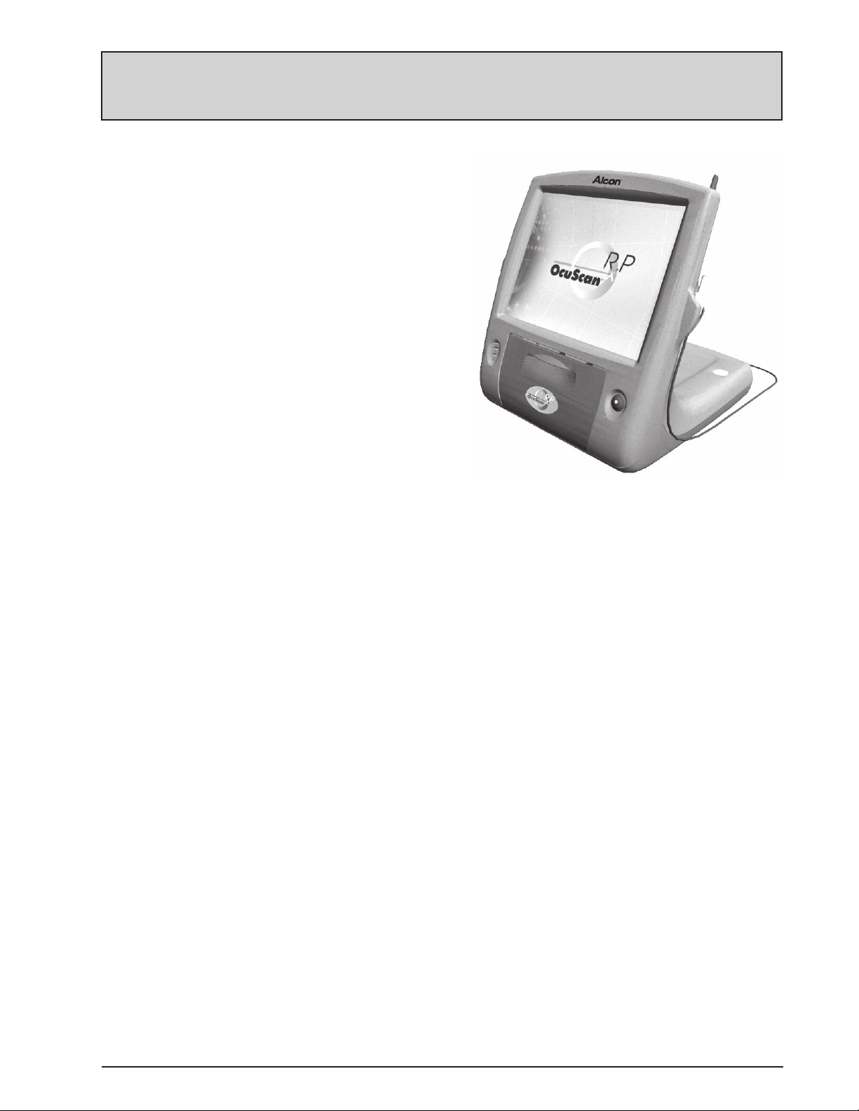
The OcuScan® RxP Measuring System
The OcuScan® RxP Measuring
System is an ophthalmic ultrasound
system designed to enhance patient
care by providing high quality eye
measurements in an easy to use format.
The system is used for A-scan Biometry
and Pachymetry applications.
Biometry consists of measuring the
axial length of the eye. By applying
axial length (AL) and keratometry (K)
readings into various IOL calculation
formulas, the system calculates the
power of the intraocular lens to be
implanted in the patient's eye.
Figure 1-1 OcuScan® RxP Measuring System
Pachymetry consists of measuring corneal thickness at one or several points on the cornea.
It is often performed during a Biometry examination and prior to refractive surgery such
as Lasik or PRK. Corneal thickness measurements may aid in determining the risk of
developing Glaucoma and the evaluation of intraocular pressure (IOP).
Please take a few minutes to familiarize yourself with the
OcuScan® RxP Measuring
System by scanning patients with previously known diagnoses and measurements.
Experiment with various clinical situations until you feel comfortable with your
new system. Various enhancements have been made in both Contact and Immersion
modes, therefore if you are using customized constants derived on a system other than
the OcuScan® RxP Measuring System, it is recommended to derive new customized
constants using the OcuScan® RxP Measuring System.
This operator's manual is designed to provide the necessary information for setting up
and learning to operate the system, and to provide a reference source for the various
menus and selections.
The most effective use of
diagnostic ultrasound requires a complete understanding of
the functional aspects of the instrument and the clinical significance of ultrasound traces.
Users of ultrasonic equipment should study professional literature and obtain approved
medical training in the interpretation of ultrasound traces and in obtaining accurate
measurements of the eye's axial length and corneal thickness. Professional literature
should also be used to decide on the appropriate IOL power calculation formula for a
particular patient.
8065750127 1.1
Page 10

OcuScan
®
RxP Measuring System
QUICK START
1. INSTALL THE SYSTEM
1.1 Perform the installation instructions on the next page.
NOTE: For detailed setup information, refer to Section Three: Operating Instructions.
2. SYSTEM SETUP
2.1 From the Menu screen, tap (or press) System Setup.
2.2 Input the Clinic and Operator names. Tapping on a field will display a keyboard that allows
you to input the textual information. There are five operator's selections that can be named
as desired.
2.3 Set the action of the Print/Save button using the Records selection. Tapping the button
advances through the four selections as follows: Current Screen, Full Report, Full Report
and Save, and Display Menu.
2.4 Enter the Date and Time.
2.5 Select a Language.
2.6 Select the Video Mode: LCD only or SVGA mode to connect an external monitor.
2.7 Select a Save Patient Format. Use PC Format if you plan to export patient data to a Personal
Computer, otherwise use Compact Flash format to conserve space on the optional Compact
Flash card.
2.8 Tap OK to return to the Menu screen. When prompted, tap the checkmark button to save
the changes.
3. SETTING UP THE BIOMETRY PRESETS
3.1 From the Menu screen, tap the Biometry button.
3.2 Tap in the Settings frame to enter the Biometry Presets screen.
3.3 Enter a name for each of the five available Presets as desired. Change to a different preset
by tapping on the Preset drop down menu then tap on a different Preset number.
3.4 Change the default Settings as necessary.
3.5 Select the screens in the Secquence box that will be displayed during the procedure. The
Sequence determines which screen will be displayed next when tapping the Next arrow
button. When the end of the sequence is reached, the system loops back to the beginning.
3.6 If necessary, edit the Pseudo or Phakic IOL Defaults to your desired values. First select a
Material then tap the Edit button. Enter the desired changes in the IOL Edit box.
3.7 Enter your preferred lenses in the Lens Constant screen.
3.8 Tap OK to return to the Biometry Scan screen. When prompted, tap the checkmark button
to save the changes.
4. ENTERING PATIENT DATA
4.1 Tap the
Patient frame.
4.2 Tap the New Patient button.
4.3 Enter a Patient Name and ID. A patient ID is required to save patient data.
4.4 Select the desired Preset
and Operator. These were setup in the previous steps.
4.5 Enter the patient data for each eye.
4.6 Tap the arrow button to return to the Biometry Scan
5. The OcuScan® RxP Measurement System is now ready to perform biometry examinations and
calculate the IOL power.
NOTE: Be sure to save the data after the exam. The Save button is available on the Patient
Information screen or by pressing the Print/Save button if it is programmed to Display Menu.
1.2 8065750127
Page 11

OcuScan
®
RxP Measuring System
INSTALLATION INSTRUCTIONS
The
OcuScan® RxP Measuring System is shipped in damage resistant cardboard
crates. The components must be removed from the crates, set on a secure work
surface, and assembled as described below. Be sure to make cable connections
exactly as instructed.
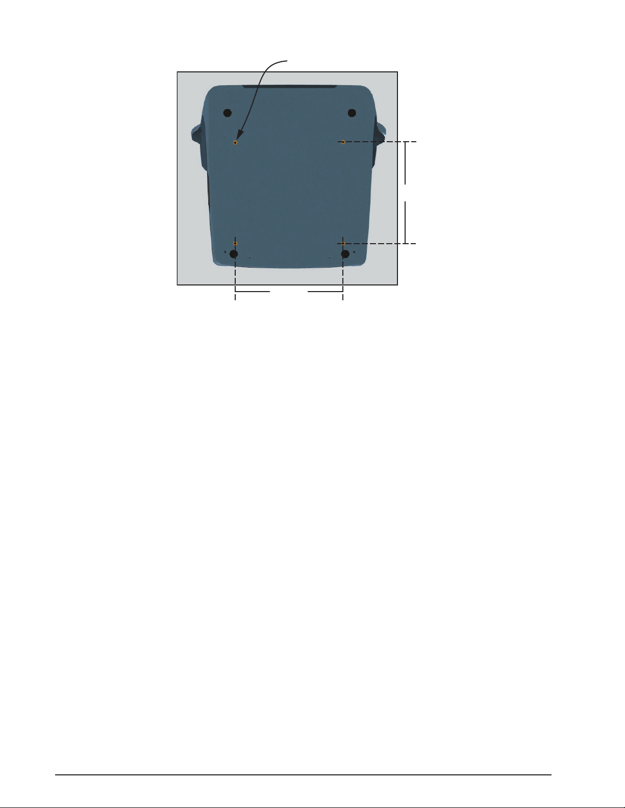
NOTE: Four threaded holes are provided on the bottom side of the console to
attach the system to a cart or table if desired. Refer to Figure 1-2 for layout and
dimensions of the hole pattern.
1 From the external power supply unit, plug the 24 VDC power input cable
connector into the OcuScan® RxP rear panel (see Figure 2-2).
2 From the external power supply unit, plug the power cord into a 110-120 VAC
or 200-240 VAC power source. The power supply is self-adjusting and will
adapt automatically to either power source. NOTE: The power cord used to
connect the power supply to the wall outlet is shipped with systems for
use in the U.S.A. and Canada only. For other countries, a power cord with
appropriate ratings and national safety agency approval must be used.
3 Set the footswitch on the floor and plug its cable connector into the footswitch
mini din connector on the OcuScan® RxP rear panel .
4 Plug the biometry probe cable into the BIOMETRY connector on the rear
panel, then place the probe in the probe holder on the right side of the console
with the probe tip pointing upwards. Plug the pachymetry probe cable into the
PACHYMETRY connector, then place the probe in the probe holder on the left
side of the console with the probe tip pointing upwards.
5 Verify that a paper roll is installed in the printer compartment on the front of
the console. If not, install a new paper roll as detailed in Section Four: Care and
Maintenance.
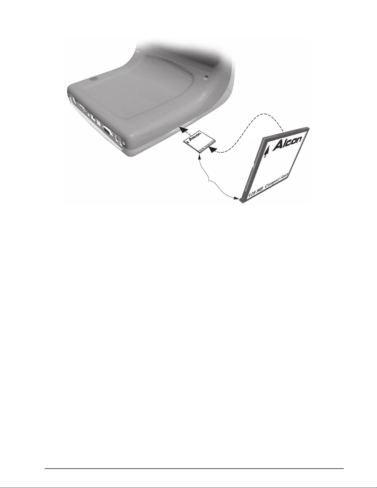
6 If a Patient Records Compact Flash card has been purchased with the system,
insert it into the slot on the left side of the console with the insert arrow facing
up and pointing towards the slot (see Figure 1-3).
7 Place the stylus into the holder on top of the console (see Figure 2-1).
8
If you have power supply model PMP130-14-S
, turn the system ON by pressing
the switch on the external power supply to the ON position.
If you have power supply model PCM 80PS24
, the power will turn on when the
power cord is plugged into the wall outlet. The LED on this model indicates that
the power is on.
8065750127 1.3
Page 12
OcuScan
Mounting Holes (4x)
51/2 in.
611/16 in.
Figure 1-2 MOUNTING HOLES - The system can be mounted to a cart or table using the threaded mounting holes
shown in this illustration. Use screws with a M5 x 0.8 thread and the appropriate length to extend
through the surface of the table or cart.
®
RxP Measuring System
INSTALLING OPTIONAL SOFTWARE AND UPGRADING SYSTEM SOFTWARE
Optional software is available for the
OcuScan® RxP Measuring System and can
be ordered by following the directions in Section Six: Accessories and Parts. The
optional software and system software upgrades are delivered on a Compact Flash
card and are installed as follows:
1 Insert Compact Flash card containing new software into the slot on the side of
the system as shown in Figure 1-3.
2 For systems with REF number 685-0000-501 (see label behind display panel),
turn the system power OFF then back ON.
For systems with REF number 685-0000-502 and above, reset the system
by pressing and holding the standby switch for 7 seconds. The software is
automatically installed. When upgrading the system software, a status bar is
displayed showing the progress of the upgrade installation.
NOTE: The Compact Flash card containing the optional software will only
work for one upgrade and the same card can be used for storing patient
data thereafter. It is recommended to re-label the card if using it for patient
data.
1.4 8065750127
Page 13
OcuScan
Ridge faces down when
inserting card.
®
RxP Measuring System
Figure 1-3 INSERTING THE COMPACT FLASH CARD - Insert the Compact Flash card as shown in this
figure.
8065750127 1.5
Page 14

OcuScan
®
RxP Measuring System
NOTES, CAUTIONS, AND WARNINGS
NOTES:
• All data that has been entered or displayed on any screen must be verified
by the operator for correctness and completeness before progressing from
one screen to another.
• It is recommended to perform a probe check prior to starting a biometry
session. A probe check should also be done when a new probe is used.
• On systems 685-0000-502 and above (see REF number on label), pressing
and holding the standby switch for 7 seconds then releasing will reset
(reboot) the system.
CAUTIONS
• This device is intended for healthcare professionals who are trained in
A-scans, IOL power calculations, and/or pachymetry measurements.
• Do not clean console and accessories with solvents or abrasives; irreparable
damage will result.
•
Biometry and Pachymetry probes are fragile components which must not
undergo rough use or handling; this can destroy or alter operation of the probe.
• Avoid touching touch screen with gel or sterile prism solution.
• To ensure compliance with IEC 601-1-1 (requirements for medical electrical
systems), do not use power strips (portable multiple socket outlets) to power
the
OcuScan
®
RxP system.
• Using the system with a hospital grade power cord and proper hospital grade
grounded electrical outlet assures electrical safety.
• In accordance with ALARA principles, the energy delivered to the eye should
be as low as is reasonably achievable.
• If the identification of the IOL or its constants is changed, be sure to update
the A Constant, S-Factor, and ACD.
• Consult the IOL manufacturer if you have questions regarding IOL
constants.
• It is very important to verify that the correct default velocities and
thicknesses are displayed prior to measuring Axial lengths and corneal
thickness.
• Prior to initiating the COMPUTE function in the LENS CONSTANT
UPDATE screen, verify the data entered is correct.
WARNINGS!
•
The Alcon Laboratories ultrasound probes and equipment are NOT designed
or intended for fetal use.
• Not suitable for use in the presence of flammable anesthetic, oxygen, or
nitrous oxide.
• Do not use this product on eyes when corneal integrity is compromised by
infection or trauma.
• Do not use the system if it displays error messages or acts erratically.
1.6 8065750127
Page 15

OcuScan
®
RxP Measuring System
EMC Statement
It is important to install and use the equipment in accordance with the instructions
in order to prevent harmful interference with other devices in the vicinity. If this
equipment causes harmful interference to other devices (determined by turning the
equipment off and on), the user is encouraged to try to correct the interference by one
or more of the following measures:
• Reorient or relocate the other device(s).
• Increase the distance between the equipment.
• Connect this equipment into an outlet on a circuit different from that to which the
other device(s) is connected.
• Consult the manufacturer or your Alcon field service engineer for help.
CAUTION
The OcuScan® RxP Measuring System needs to be installed and put into service
according to the EMC information provided in Tables 1-1 through
1-3. Portable and mobile RF communications equipment can affect this medical
electrical equipment.
Use of accessories and cables other than those provided may result in increased
emissions or decreased immunity of the system.
The
OcuScan® RxP Measuring System is intended for use in the electromagnetic
environment specified in Tables 1-1 and 1-2. The customer or the user of
the OcuScan® RxP Measuring System should assure that it is used in such an
environment.
8065750127 1.7
Page 16

Table 1-1
Electromagnetic Emissions
OcuScan
®
RxP Measuring System
Emissions Test
RF emissions
CISPR 11
RF emissions
CISPR 11
Harmonic emissions
IEC 61000-3-2
Voltage fluctuations/
flicker emissions
IEC 61000-3-3
Immunity Test
Electrostatic
discharge (ESD)
IEC 61000-4-2
Compliance
Group 1
Class B
Class A
Complies
IEC 60601 Test Level
• +6 kV contact
• +8 kV air
Electromagnetic Environment-Guidance
The
OcuScan
®
RxP Measuring System uses RF energy only for its
internal function. Therefore, RF emissions are very low and are not
likely to cause any interference in nearby electronic equipment.
The
OcuScan
®
RxP Measuring System is suitable for use in all
establishments, including domestic establishments and those directly
connected to the public low-voltage power supply network that supplies
buildings used for domestic purposes.
Table 1-2
Electromagnetic Immunity
Compliance Level
• +6 kV contact
• +8 kV air
Electromagnetic Environment-Guidance
Floors should be wood, concrete, or ceramic tile.
If floors are covered with synthetic material, the
relative humidity should be at least 30%.
Electrical fast
transient/burst
IEC 61000-4-4
Surge
IEC 601-4-5
Voltage dips, short
interruptions, and
voltage variations
on power supply
input lines
IEC 61000-4-11
Power frequency
(50/60 Hz)
magnetic field
IEC 601000-4-8
• +2 kV for power
supply lines
• +1 kV for input/
output lines
• +1 kV differential
mode
• +2 kV common
mode
• <5% U
in UT for 0.5 cycle)
• 40% U
UT for 5 cycles)
(>95% dip
T
(60% dip in
T
• 70% (30% dip in U
for 25 cycles)
• <5% (>95% dip in
UT for 5 sec)
3 A/m
• +2 kV for power
supply lines
• +1 kV for input/
output lines
• +1 kV differential
mode
• +2 kV common
mode
• <5% U
• 40% U
• 70% (30% dip in U
T
(>95% dip
T
in UT for 0.5 cycle)
(60% dip in
T
UT for 5 cycles)
for 25 cycles)
• <5% (>95% dip in
UT for 5 sec)
3 A/m
Mains power quality should be that of a typical
commercial or hospital environment.
Mains power quality should be that of a typical
commercial or hospital environment.
Mains power quality should be that of a typical
commercial or hospital environment. If the
uses of the
OcuScan
®
RxP Measuring System
requires continued operation during power
mains interruptions, it is recommended that the
OcuScan
from an uninterruptible power supply or a battery.
T
®
RxP Measuring System be powered
Power frequency magnetic fields should be at
levels characteristic of a typical location in a
typical commercial or hospital environment.
Note: UT is the AC mains voltage prior to application of the test level.
Table 1-2 continued on the next page...
1.8 8065750127
Page 17
OcuScan
®
RxP Measuring System
...continued from previous page.
Table 1-2
Electromagnetic Immunity
Immunity Test
Conducted RF
IEC 61000-4-6
Radiated RF
IEC 6100-4-3
IEC 60601 Test Level
3 Vrms
150 kHz to 80 MHz
3 V/m
80 MHz to 2.5 GHz
Compliance Level
3 Vrms
3V/m
Electromagnetic Environment-Guidance
Portable and mobile RF communications
equipment should be used no closer to any
part of the
OcuScan
®
RxP Measuring System,
including cables, than the recommended
separation distance calculated from the equation
applicable to the frequency to the transmitter.
Recommended separation distance:
d = 1.2√P 150 kHz to 80 MHz
d = 1.2√P 80 MHz to 800 MHz
d = 2.3√P 800 MHz to 2.5 GHz
where P is the maximum output power rating
to the transmitter in watts (W) according to
the transmitter manufacturer and d is the
recommended separation distance in meters (m).
Field strength from fixed RF transmitters, as
determined by an electromagnetic site surveya,
should be less than the compliance level in each
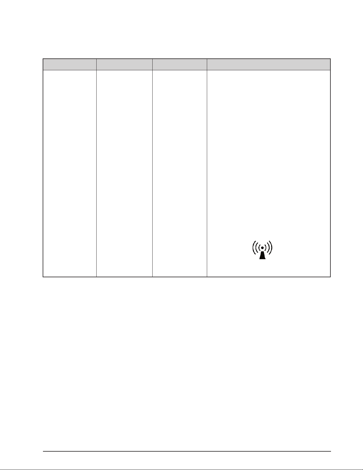
frequency rangeb.
Interference may occur in the vicinity of
equipment marked with the following symbol.
Note 1: At 80 MHz and 800 MHz, the separation distance for the higher frequency range applies.
Note 2: These guidelines may not apply in all situations. Electromagnetic propagation is affected by absorption and
reflection from structures, objects, and people.
a
Field strengths from fixed transmitters, such as base stations for radio (cellular/cordless) and land mobile radios,
amateur radio, AM and FM radio broadcast, and TV broadcast cannot be predicted theoretically with accuracy. To
access the electromagnetic environment due to fixed RF transmitters, an electromagnetic site survey should be
considered. If the measured field strength in the location in which the (equipment or system) is used exceeds the
applicable RF compliance level above, the (equipment or system) should be observed to verify normal operation. If
abnormal performance is observed, additional measures may be necessary, such as re-orienting or relocating the
OcuScan
b
Over the frequency range 150 kHz to 80 MHz, field strengths should be less than 3 V/m.
®
RxP Measuring System.
8065750127 1.9
Page 18

OcuScan
®
RxP Measuring System
The OcuScan® RxP Measuring System is intended for use in an electromagnetic
environment in which radiated RF disturbances are controlled. The customer or
the user of the OcuScan® RxP Measuring System can help prevent electromagnetic
interference by maintaining a minimum distance between portable and mobile RF
communications equipment (transmitters) and the OcuScan® RxP Measuring System
as recommended in Table 1-3, according to the maximum output power of the
communications equipment.
Table 1-3
Recommended Separation Distances Between Portable and Mobile
RF Communications Equipment and the
Rated maximum output
power of transmitter
(W)
0.01
0.1
1
10
100
Separation distance according to frequency of transmitter
150 kHz to 80 MHz
d = 1.2√P
0.12
0.38
1.2
3.8
12
OcuScan
80 MHz to 800 MHz
®
RxP Measuring System
(m)
d = 1.2√P
0.12
0.38
1.2
3.8
12
800 MHz to 2.5 GHz
d = 2.3√P
0.23
0.73
2.3
7.3
23
Note 1: For transmitter rates at a maximum output power not listed above, the recommended separation distance d in
meters (m) can be estimated using the equation applicable to the frequency of the transmitter, where P is the
maximum output power rating of the transmitter in watts (W) according to the transmitter manufacturer.
Note 2: At 80 MHz and 800 MHz, the separation distance for the higher frequency range applies.
Note 3: These guidelines may not apply in all situations. Electromagnetic propagation is affected by absorption and
reflection from structures, objects, and people.
1.10 8065750127
Page 19

OcuScan
®
RxP Measuring System
Universal Precautions
Universal precautions shall be observed by all people who come in contact with the
instrument and/or accessories to help prevent their exposure to blood-borne pathogens
and/or other potentially infectious materials. In any circumstance, wherein the exact
status of blood or body fluids/tissues encountered are unknown, it shall be uniformly
considered potentially infectious and handled in accordance with OSHA guidelines.
Underwriter's Laboratories
The
OcuScan
®
RxP Measuring System is classified by Underwriter's Laboratories,
Inc., with respect to Electric Shock, Fire, Mechanical, and other specified hazards
only in accordance with UL 2601-1 and CAN/CSA C22.2 No. 601.1.
Accessory Equipment
Accessory equipment connected to or used with this equipment must be certified
according to the respective IEC standard (e.g. IEC 950 for data processing equipment
and IEC 601-1-1 for medical equipment). Furthermore, all configurations shall
comply with the system standard IEC 601-1-1. Anyone connecting additional
equipment, or otherwise causes a different system configuration than provided by
Alcon, is responsible for continued compliance to the requirements of the system
standard IEC 601-1-1. If in doubt, consult Alcon Technical Services at 949/753-1393
or contact your local Alcon representative.
Environmental Issues
Follow local governing ordinances and recycling plans regarding disposal or
recycling of device components and packaging.
User Information – Environmental Considerations
The equipment that you have purchased requires the use of natural resources for its
production. This equipment may also contain hazardous substances which could have
potential effect on the environment and human health if disposed of improperly.
In order to avoid the entry of any such substances into our environment and to
promote natural resource conservation, we encourage you to use the appropriate takeback systems. Such take-back systems reuse or recycle many of the materials in your
end-of-life equipment in a beneficial way. Please contact your local Alcon office for
assistance in take-back options through Alcon or other providers.
The crossed-bin symbol located on this equipment reminds you to use take-back
systems, while also emphasizing the requirement to collect waste equipment
separately, and not dispose of it as unsorted municipal waste.
If you need more information on the collection, reuse or recycle systems available to
you, please contact your local or regional waste administration, or contact your local
Alcon office for more information.
8065750127 1.11
Page 20

Safety Requirements
OcuScan
®
RxP Measuring System
The
OcuScan® RxP Measuring System complies with the following safety agency
standards for medical instruments: IEC 601-1, IEC 601-1-1, IEC 601-1-2, IEC
601-1-4, UL 2601. The system meets all essential requirements of Medical Device
Directives 93/42/EEC.
The system complies with FDA acoustic power measurement limits, IEC 60601-2-37
and meets the Acoustic Output Declaration Exemption for IEC 1157.
1 - Acoustic Output Measurements Statistical analysis of Ultrasound Power Measurements per FDA 510(k) Diagnostic
Ultrasound Guidance.
Probe I
X MI X
spta
10 MHz Biometry 0.12 0.21
20 MHz Pachymetry probe 0.51 0.13
I
X is the derated spatial-peak temporal-average intensity in mW/cm2 (milliwatts
spta
per square centimeter). MI is the Mechanical Index. X stands for upper output
parameter statistical limits.
2 - IEC 1157 – Acoustic Output Declaration Exemption
The
OcuScan® RxP Measuring System meets the three exemption conditions specified
by IEC 1157 as follows:
• The peak-negative acoustic pressure does not exceed 1 MPa.
2
• The output beam intensity does not exceed 20 mW/cm
• The spatial-peak temporal-average intensity does not exceed 100 mW/cm
.
2
.
The averages of the measurements conducted per IEC 1157 of several samples of the
10 MHz Biometry and 20 MHz Pachymetry probes were as follows:
Probe Biometry Pachymetry
Peak negative acoustic pressure (MPa) 0.69 0.54
Output beam intensity (mW/cm
Spatial-peak temporal-average intensity (mW/cm
2
) 0.03 0.09
2
) 0.15 0.57
(10MHz) (20MHz)
1.12 8065750127
Page 21

OcuScan
®
RxP Measuring System
PRODUCT SERVICE
For product service, please contact Alcon's Technical Services Department at the number
provided below.
Operators experiencing problems with the system should refer to the Operating Instructions
and Troubleshooting sections of this manual. A problem which persists should be referred to
the Alcon Technical Services Department or your local authorized service representative.
For optimum performance, it is the user's responsibility to schedule preventive maintenance
service on the system and its accessories one time each year. Alcon's Field Service Engineers
are trained and equipped to provide the highest quality of workmanship.
Safety performance should be verified by the user (e.g., qualified service personnel) at least
twice a year. Ground resistance, leakage current and dielectric withstand voltage must be
checked to appropriate national standard.
To avoid unnecessary shipping, please contact your Alcon Technical Services Department
prior to return of any system or accessories. If return of the equipment is deemed necessary,
a Return Material Authorization will be issued with appropriate shipping instructions.
Alcon Laboratories, Inc.
Technical Services Department
15800 Alton Parkway
Irvine, California 92618-3818
(949) 753-1393 or (800) 832-7827
LIMITED WARRANTY
Alcon will repair or replace at its option, any system or accompanying accessories
found to be defective in material and/or workmanship for a period of one (1) year from
the date of initial installation. This warranty applies to the original purchaser of the
system, when said system is properly installed, maintained, and operated in accordance
with published instructions.
Alcon shall not be obligated to provide services under this warranty for damage to
or destruction of systems covered where such damage or destruction is a result of or
caused by fire or explosion of any origin, riot, civil commotion, aircraft, war, or any Act
of God including, but not limited to lightning, windstorm, hail, flood or an earthquake.
This warranty does not cover damage resulting from service repair or other alteration by
any person other than an Alcon-authorized service person, and any warranties provided
by Alcon with respect to this equipment shall become void and of no further force
and effect if this equipment is serviced by anyone other than Alcon-authorized service
personnel. In particular, Alcon shall have no obligation to replace, repair or credit
customerʼs account for the cost of the equipment, which has been subject to service or
other alteration by persons other than Alcon-authorized service personnel.
THE EXPRESS WARRANTY ABOVE IS THE SOLE WARRANTY
OBLIGATION OF ALCON, AND THE REMEDY PROVIDED ABOVE
IS IN LIEU OF ANY AND ALL OTHER REMEDIES. THERE ARE NO
OTHER AGREEMENTS, GUARANTEES, OR WARRANTIES – ORAL
OR WRITTEN, EXPRESS OR IMPLIED – INCLUDING, WITHOUT
LIMITATION, WARRANTIES OF MERCHANTABILITY OR FITNESS
FOR A PARTICULAR PURPOSE. ALCON SHALL HAVE NO LIABILITY
WHATSOEVER FOR ANY INCIDENTAL OR CONSEQUENTIAL DAMAGES
ARISING OUT OF ANY DEFECT, IMPROPER USE, OR UNAUTHORIZED
SERVICE OR REPAIR.
8065750127 1.13
Page 22
OcuScan
Table 1-4
OCUSCAN® RxP SYSTEM SPECIFICATIONS
®
RxP Measuring System
CONSOLE DIMENSIONS
Height: 30.5 cm (12.0 inches)
Width: 30.5 cm (12.0 inches)
Depth: 27.9 cm (11.0 inches)
WEIGHT Packed Unpacked
Console & Accessories 6.62 kg 4.85 kg
(14.60 lbs) (10.70 lbs)
ENVIRONMENTAL REQUIREMENTS
Operating Storage
Temperature: 10° C to 35° C -10° C to 55° C
50° F to 95° F -18° F to 131° F
Altitude: -125 m to +2500 m -125 m to +6100 m
Humidity: 30% to 75% 10% to 95%
Noise Level: Sound pressure level does not exceed
44 dbA measured at one meter.
ELECTRICAL CHARACTERISTICS
The instrument automatically sets itself to operate with the
supplied voltage and frequency.
Input AC Voltage/Current: 100-120 V~/200-240 V~, 2A
to power supply
Frequency: 50/60 Hz
Input DC Voltage/Current: 24 VDC ±2V with minimum of
to console 3.3 A from an external power
module.
Insulation Class: Class I, type BF
Continuous operation.
SYSTEM PERFORMANCE
Internal Video Display: SVGA 800 x 600
External Video: SVGA
Biometry
Probe frequency: 10 MHz ±1 MHz
Theoretical Accuracy: ±0.05 mm
Clinical Accuracy: ±0.1 mm
Axial Length Range: 15 - 39 mm
Gain Range: Adjustable from 40 to 80 dB
Memory: Biometry Measurements: 10 per eye
Physician Settings: 5
IOL Slots per Setting: 10 (editable)
Display: AL (10), average AL,
Standard Deviation, Lens thickness,
ACD, and Vitreous
IOL Formulas: Holladay®, SRK II, SRK T,
Binkhorst II, Hoffer Q,
Haigis (optional)
Pachymetry
Probe frequency: 20 MHz ±2 MHz
Resolution: ±1 µm
Accuracy: ±5 µm
Measurement Range: 100-350, 400-700, and 300-1100 µm
Bias:
Actual: Actual measurement
Percentage: 0 to 300%
Absolute: -999 to 999 µm
Gain: Auto adjusting
Memory:
Single Point: 10 programmable points
Map 1 or 2: 25 programmable points
LASIK: 3 points in each of four phases
Physician settings: 5
Display:
Single Point: Min, Avg, SD, Adjusted IOP
Map 1 or 2: Last, Average, and Minimum readings
LASIK: Minimum reading, Flap achieved,
Potential Ablation, Ablated, Potential
Enhancement
1.14 8065750127
Page 23
OcuScan
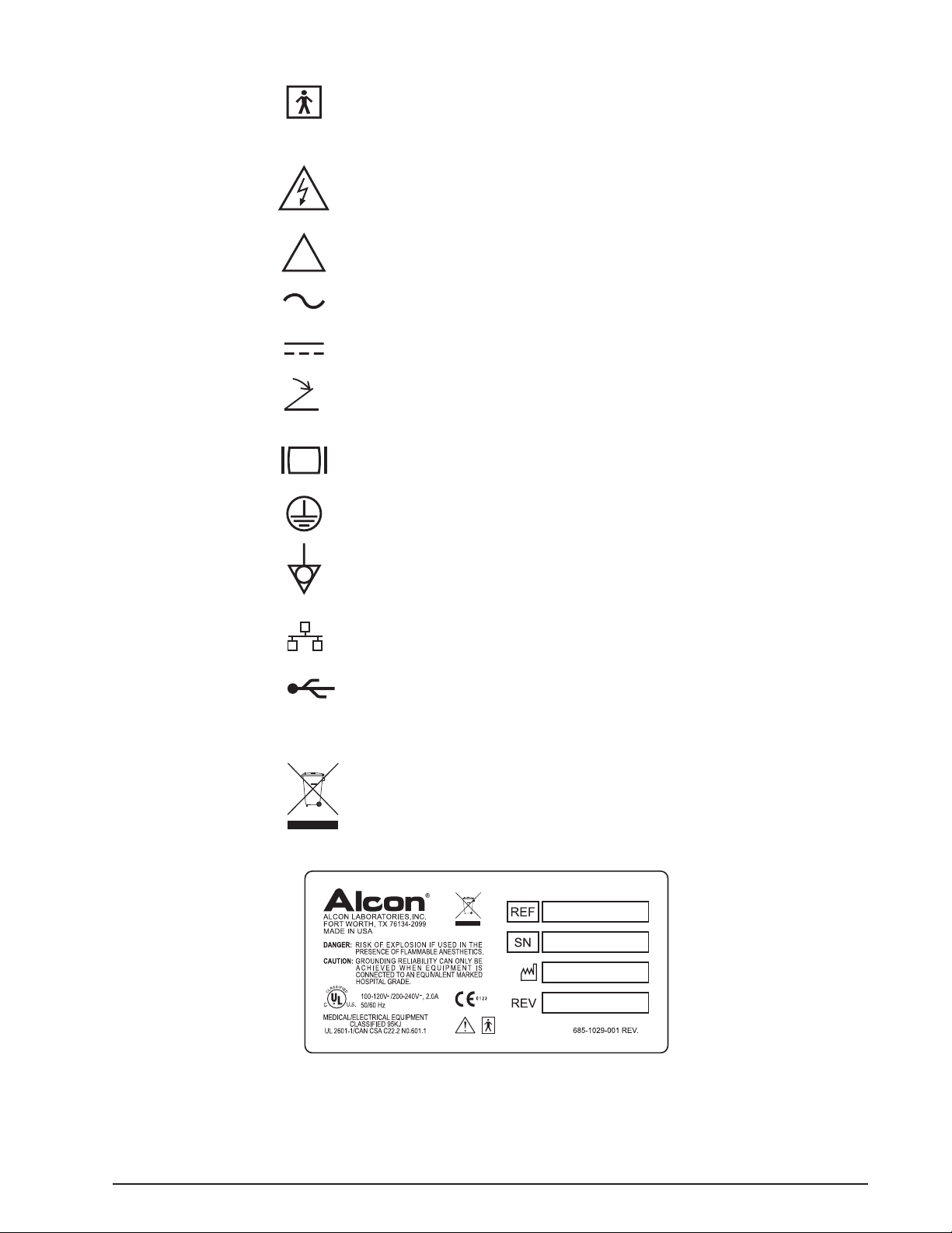
TYPE BF EQUIPMENT, providing both the
attributes of basic insulation and "floated"
isolation.
Dangerous Voltage
Used for U.S. Approval to Indicate:
Caution: To reduce the risk of electric shock,
do not remove cover (or back). Refer
servicing to qualified service personnel.
Attention, consult ACCOMPANYING DOCUMENTS
Alternating current
Direct current
Footswitch connection
SVGA color video
Protective ground
Equipotential ground connection
Ethernet Connection
USB Connection
RS232 Serial Connection
Use appropriate take-back system
(See Environmental Considerations in this manual)
!
101010
®
RxP Measuring System
Figure 1-4. OcuScan® RxP LABELS AND ICONS - Shown here are the assorted labels and icons printed on the
console and components.
8065750127 1.15
Page 24

OcuScan
®
RxP Measuring System
IOL CALCULATION FORMULAS
Description of common variables :
AL: Axial length measured
K: Average diopter power of the cornea = (K1 + K2) / 2
R: Curvature of the cornea in mm = 337.5 / K (in diopters)
ACD: Post-operative anterior chamber depth is the value entered in the IOL file. The
value is supplied by the IOL manufacturer and is used by the BINKHORST II
formula except where correction is made to ACD.
KERATOMETRY
On axis 0, K1 = 28 D to 62 D in diopters
On axis 0, K2 = 28 D to 68 D in diopters
On axis 90°, K2 = 5 mm to 13 mm radius of curvature in mm
K = (K1 + K2) / 2
K in diopters, K = 337.5 / Kmm
Refraction index used: 1.3375
BIOMETRY
AL = Axial length (17 to 40 mm)
L = Axial length
BINKHORST II VARIABLES :
LB2: Axial length corrected for Binkhorst II
LB2 = AL + 0.1984 mm
ACDbnk: Corrected anterior chamber depth only for the posterior chamber IOL.
If LB2 < 26, then ACDbnk = ACD (LB2 / 23.45)
If LB2 ≥ 26, then ACDbnk = ACD (26 / 23.45), i.e., ACDbnk = 1.1087 x ACD
NOTE: When the IOL TYP (type) is labeled anterior, the ACD value does not
require correction. When the IOL TYP (type) is labeled posterior, the ACD value is
corrected and the IOL power will change.
1.16 8065750127
Page 25

OcuScan
Rag2 –
AG2
4
IOLam =
1336 (1.336R – 0.3333LC – 0.001Tam (16.032R – 4LC + LC x R))
(LC – CA) (1.336R – 0.3333CA
– 0.001Tam (16.032R – 4CA + CA x R))
Tam =
1336 (1.336R – 0.3333LC) – IOLam (LC – CA) (1.336R – 0.3333CA)
1.336 (16.032R – 4LC + LC x R) – 0.001IOLam (LC – CA) (16.032R – 4CA + CA x R)
®
RxP Measuring System
HOLLADAY VARIABLES :
L: Axial length in mm
Lhol: Axial length corrected for HOLLADAY
Lhol = L + 0.200 mm
SF: Surgeon Factor proper for HOLLADAY formula
SF = (0.5663 x A) - 65.60, where A = SRK Constant
This calculation per default is proposed when parameters are entered in IOL files. If the
operator modifies SF, it is this new coefficient which will be used.
CAhol: Anterior chamber corrected for HOLLADAY
Rag = R except if R < 7 mm, then Rag = 7 mm
AG = (12.5/23.45) L; i.e., AG = 0.533 x L, except if AG >13.5, then AG = 13.5 mm
ACDH = 0.56 + Rag -
CAhol = ACDH + SF
Common formulas for BINKHORST II and HOLLADAY :
R: Curvature of the cornea in mm = 337.5 / K (with K in diopters)
LC: Axial length corrected
CA: Post-operative anterior chamber
IOLam: IOL power for ametropia
For BINKHORST :
LC = LB2
CA = ACD for anterior chamber, or ACDbnk for posterior chamber
For HOLLADAY :
LC = Lhol
CA = CAhol
Formula which gives the IOL value depending on the desired target ametropia (or
refraction) Tam:
IOLam = f (Tam)
if Tam = 0 then IOLam = IOLem (emmetropic)
Formula which gives the refraction value depending on the desired IOLam:
Tam = f (IOLam)
8065750127 1.17
Page 26

OcuScan
®
RxP Measuring System
HOFFER-Q FORMULAS:
P = IOL power in Diopters A = Axial length in mm
R = Refractive error at corneal plane Rx = Refractive error at spectacle
K = K Average in Diopters C = ACD: Anterior Chamber Depth in mm
pACD = personalized ACD (in lens constants)
Constants:
Refractive index of cornea = 1.336 Retinal thickness factor = 0
Vertex distance (glasses) = 12 mm
Hoffer Formula: IOL Power
R = Rx/(1-0.012 Rx)
P = (1336/(A - C - 0.05)) - (1.336/((1.336/(K + R)) - ((C + 0.05)/1000)))
Hoffer Formula: Refractive Error
R = (1.336/(1.336/(1336/(A - C - 0.05) - P) + (C+0.05)/1000))-K
Hoffer Q Formula: Predicted ACD
ACD = pACD + 0.3 (A - 23.5) + (tan K)2 + (0.1 M (23.5 - A)2 (tan (0.1 (G - A)2)) - 0.99166
For Predicted ACD:
If A< 18.5, then A = 18.5
If A> 31.0, then A = 31.0
If A< 23, then M = +1 and G = 28
If A>23, then M = -1 and G =23.5
1.18 8065750127
Page 27

OcuScan
®
RxP Measuring System
SRK-II FORMULAS :
P = Emmetropic power
I = Desired IOL power
Rf = Refraction factor
L = Measured axial length (mm)
K = Averaged Keratometry (D)
A = SRK and SRK II A Constant
Emmetropic power: P = A – 2.5 L – 0.9 K + C
C = Correction with respect to original SRK formula where C = 0
C values according to the measured axial length :
If L < 20 mm, then C = 3
If 20
< L < 21, then C = 2
If 21 < L < 22, then C = 1
If 22 < L < 24.5, then C = 0
If L > 24.5 mm, then C = –0.5
Ametropia values :
with: P = Emmetropia power
I = Desired IOL power
Rf = Refraction factor
Tam = Target Ametropia
Refraction = f(I): Tam = (P-I) / Rf where Rf = 1.25 if P > 14; Rf = 1 if P ≤ 14
IOL = f(Tam): I = P – (Tam x Rf) where Rf = 1.25 if P > 14; Rf = 1 if P ≤ 14
8065750127 1.19
Page 28

SRK-T FORMULAS :
IOLam =
1336 x (C6 - (0.001 x Tam x C8))
C4 x (C5 - (0.001 x Ta
m x C9))
Tam =
(1336 x C6) - (IOLam x C4 x C5)
(1.336 x C8) - (0.001 x IOLam x C4 x C9)
L = Measured Axial length (mm)
Lcor = Corrected axial length (mm)
Rcor = Corneal Radius of curvature (mm)
K = Average K (D)
crwdest = Computed corneal width (mm)
ACDT = ACD-Constant from the A-Constant
ACDest = Estimated postoperative ACD for patient
Retinal thickness: Rethick = 0.65696 – 0.02029 x L
OcuScan
®
RxP Measuring System
Lcor = L if L
< 24.2
Lcor = –3.446 + (1.716 x L) – (0.0237 x L2) if L > 24.2
Rcor = 337.5 / K
(with K in diopters)
D
crwdest = –5.41 + 0.58412 x Lcor + 0.098 x K
SqrootR1 = (Rcor)
2
– (crwdest)2 / 4
if SqrootR1 < 0 then SqrootR1 = 0
Hest = Rcor – SqrootR1
ACDT = 0.62467 x A – 68.747 (where A = SRK Constant)
ACDest = Hest + ACDT – 3.336
na = 1.336
C2 = 0.3333
C3 = L + rethick = 0.97971 x L + 0.65696
C4 = C3 – ACDest
C5 = (na x Rcor) – (C2 x ACDest)
C6 = (na x Rcor) – (C2 x C3)
C8 = (12 x C6) + (C3 x Rcor)
V = 12 vertex distance: lens/cornea
C9 = (12 x C5) + (ACDest x Rcor)
Tam = targeted or desired postoperative refraction (D)
1.20 8065750127
Page 29

OcuScan
Rag2 –
AG2
4
®
RxP Measuring System
HOLLADAY REVERSE SOLUTION OF SURGEON FACTOR
I = Power of IOL (Diopters)
K = Average K Reading (Diopters) = (K1 + K2) / 2
R = Average Corneal Radius (mm) = 337.5 / K
SPH = Sphere (Diopters)
CYL = Cylinder (Diopters)
Aref = Actual postoperative spheroequivalent refraction = SPH + (CYL/2)
Alm = modified axial length (mm) = AL + 0.200
V = vertex distance (mm) , Default Value = 12 mm
(when Aref < -4, or when Aref > +4, user must input vertex distance)
Rag = R, if r<7 mm, then Rag = 7 mm
AG = 12.5 x (AL / 23.5), if AG > 13.5 mm, then AG = 13.5
ACD = 0.56 +ag -
AQ = 0.3333 - ( 0.001 x Aref ( ( 0.3333 x V) - R) )
BQ = 0.001 x Aref x ((0.333 x Alm x V)-(R x (Alm-(1.336 x V))))-((0.333 x Alm)+(1.336 x R))
CQ1 = 0.001 x Aref x V x ((1.336 x R) - (0.3333 x Alm) + (Alm x R))
CQ2 = (1336 ( ( 1.336 x R)-(0.333 x Alm ) - CQ1)) / I
CQ3 = (1.336 x Alm x R) - (0.001336 x Aref x Alm x V x R)
CQ = CQ3 - CQ2
SF = (((-BQ) - SQRT ((BQ2) - ( 4AQ x CQ)))/( 2 x AQ )) - ACD
8065750127 1.21
Page 30

HAIGIS FORMULAS (optional)
IOL Power for given refraction (DL):
OcuScan
®
RxP Measuring System
DL = n - n where: z = DC + R
X
(L-d) n/z - d 1 - RXd
DL = refractive power of IOL
D
= refractive corneal power
C
RX = desired refraction
n = 1.336 - refractive index of aequeous and vitreous
nC = 1.3315 - fictitious refractive index of cornea
d
= 12 mm - vertex distance between cornea and spectacles
X
R = average corneal radius
L = axial length measured by ultrasound
d = optical ACD
Refraction (RX) for given IOL power:
R
1 + d
= q-DC where: q = n [n-DL(L-d)]
X
(q-DC) n (L-d) + d [n-DL(L-d)]
X
Optical ACD (d):
For AC ≠ 0: d = a0 + a1(AC) + a2(L)
For AC = 0: d = [a0 + u(a1)] +[a2 +v (a1)] (L)
where: DC = nC - 1
X
R
AC = preoperative anterior chamber depth as measured by ultrasound
L = preoperative axial length as measured by ultrasound
u = -0.241
v = 0.139
a0, a1, and a2 are constants describing the implant IOL.
IOL Constants a0, a1, and a2:
Standard
a0 = 0.62467 (A) - 72.434; where A = A constant of the lens manufacturer
a1 = 0.4
a2 = 0.1
Optimized
In optimized mode, the constants a0, a1 and a2 are obtained by a separate optimization
process. For each patient, the actual postop refraction is used to calculate the corresponding
optical ACD. For all patients, these values are then correlated with the preop ultrasound
measurements of the (acoustical) ACD and the axial length L. Double linear regression
analysis yields the constants a0, a1 and a2. The Haigis Formula works best when optimized
®
constants are used.
OcuScan
RxP is shipped with Standard constants but user has the choice
to enter their optimized constants.
NOTE: “R” in Haigis Formula is calculated using K1 and K2. But if Kʼs are adjusted
(normally done for eyes undergone Refractive surgery) using K-Adjust then K-Haigis
is calculated for Haigis IOL power calculation.
1.22 8065750127
Page 31

OcuScan
®
RxP Measuring System
A CONSTANT (D)
110.0
110.1 .36 -3.25
110.2
110.3
110.4
110.5
110.6 .65 -2.97
110.7
110.8
110.9
111.0
111.1 .94 -2.68
111.2
111.3
111.4 1.11
111.5
111.6 1.23 -2.40
111.7
111.8
111.9
112.0
112.1 1.52 -2.12
112.2
112.3
112.4
112.5
112.6 1.81 -1.84
112.7
112.8
112.9
113.0
113.1 2.11 -1.55
113.2
113.3
113.4
113.5
113.6 2.40 -1.27
113.7
113.8
113.9
114.0
114.1 2.69 -.98
114.2
114.3
114.4
114.5
114.6 2.98 -.70
114.7
114.8
114.9
Anterior Chamber
Depth (mm)
.30 -3.31
.41 -3.19
.47 -3.14
.53 -3.08
.59 -3.02
.70 -2.91
.76 -2.85
.82 -2.80
.88 -2.74
1.00 -2.63
1.06 -2.57
1.17 -2.46
1.29 -2.34
1.35 -2.29
1.40 -2.23
1.46 -2.17
1.58 -2.06
1.64 -2.00
1.70 -1.95
1.76 -1.89
1.87 -1.78
1.93 -1.72
1.99 -1.66
2.05 -1.61
2.16 -1.50
2.22 -1.44
2.28 -1.38
2.34 -1.32
2.46 -1.21
2.51 -1.16
2.57 -1.10
2.63 -1.04
2.75 -.93
2.81 -.87
2.86 -.82
2.92 -.76
3.04 -.64
3.10 -.59
3.16 -.53
Table 1-5
Lens Constant Conversion Table
Surgeon Factor
(mm)
-2.51
A CONSTANT (D)
115.0
115.1 3.27 -.42
115.2
115.3
115.4
115.5
115.6 3.56 -.14
115.7
115.8
115.9
116.0
116.1 3.86 .15
116.2
116.3
116.4
116.5
116.6 4.15 .43
116.7
116.8
116.9
117.0
117.1 4.44 .71
117.2
117.3
117.4
117.5
117.6 4.73 1.00
117.7
117.8
117.9
118.0
118.1 5.02 1.28
118.2
118.3
118.4
118.5
118.6 5.32 1.56
118.7
118.8
118.9
119.0
119.1 5.61 1.85
119.2
119.3
119.4
119.5
119.6 5.90 2.13
119.7
119.8
119.9
4
Anterior Chamber
Depth (mm)
Surgeon Factor
(mm)
3.21 -.48
3.33 -.36
3.39 -.31
3.45 -.25
3.51 -.19
3.62 -.08
3.68 -.02
3.74 .03
3.80 .09
3.91 .20
3.97 .26
4.03 .32
4.09 .37
4.21 .49
4.26 .54
4.32 .60
4.38 .66
4.50 .77
4.56 .83
4.62 .88
4.67 .94
4.79 1.05
4.85 1.11
4.91 1.17
4.96 1.22
5.08 1.34
5.14 1.39
5.20 1.45
5.26 1.51
5.37 1.62
5.43 1.68
5.49 1.73
5.55 1.79
5.66 1.90
5.72 1.96
5.78 2.02
5.84 2.07
5.96 2.19
6.02 2.24
6.07 2.30
(continued on next page...)
8065750127 1.23
Page 32

(...continued from previous page)
Table 1-5
Lens Constant Conversion Table
OcuScan
®
RxP Measuring System
A CONSTANT (D)
120.0 6.13 2.36
120.1 6.19 2.41
120.2 6.25 2.47
120.3 6.31 2.53
120.4 6.37 2.58
120.5 6.42 2.64
120.6 6.48 2.70
120.7 6.54 2.75
120.8 6.60 2.81
120.9 6.66 2.87
121.0 6.72 2.92
121.1 6.77 2.98
121.2 6.83 3.04
121.3 6.89 3.09
121.4 6.95 3.15
121.5 7.01 3.21
121.6 7.07 3.26
121.7 7.12 3.32
121.8 7.18 3.38
121.9 7.24 3.43
122.0 7.30 3.49
122.1 7.36 3.55
122.2 7.42 3.60
122.3 7.47 3.66
122.4 7.53 3.72
122.5 7.59 3.77
Anterior Chamber
Depth (mm)
Surgeon Factor
(mm)
A CONSTANT (D)
122.6 7.65 3.83
122.7 7.71 3.89
122.8 7.77 3.94
122.9 7.82 4.00
123.0 7.88 4.05
123.1 7.94 4.11
123.2 8.00 4.17
123.3 8.06 4.22
123.4 8.12 4.28
123.5 8.18 4.34
123.6 8.23 4.39
123.7 8.29 4.45
123.8 8.35 4.51
123.9 8.41 4.56
124.0 8.47 4.62
124.1 8.53 4.68
124.2 8.58 4.73
124.3 8.64 4.79
124.4 8.70 4.85
124.5 8.76 4.90
124.6 8.82 4.96
124.7 8.88 5.02
124.8 8.93 5.07
124.9 8.99 5.13
125.0 9.05 5.19
Anterior Chamber
Depth (mm)
Surgeon Factor
(mm)
Bibliographies:
1. John A. Retzlaff, Donald R. Sanders, and Manus Kraff, Lens Implant Power Calculation, 3rd Edition, Thorofare, NJ: SLACK Incorporated, 1980.
2. Kenneth J. Hoffer M.D., The Hoffer Q Formula: A comparison of Theoretic and Regression Formulas, J Cataract Refract Surg-Vol. 19, November 1993
3. Jack T. Holladay, MD, MSEE, Standardizing Constants for Ultrasonic Biometry, Keratometry, and
Intraocular Lens Power Calculations, J Cataract Refract Surg-Vol. 23, November 1997
4. Jack T. Holladay, MD, MSEE, International Intraocular Lens & Implant Registry 2002 , J Cataract
Refract Surg. 2002; 28: 152-174.
LAST PAGE OF SECTION
1.24 8065750127
Page 33

OcuScan
Pachymetry Probe
LCD Touch Screen
and Display
Speaker
Compact Flash Card Slot
(shown with card installed)
Removeable Stylus
(inserted in holder)
Biometry Probe
Standby Switch
Internal Printer
(behind paper loading door)
O
c
uS
c
a
n
R
x
P
®
RxP Measuring System
General Description
SECTION TWO
DESCRIPTION
The
OcuScan® RxP Measuring System is a diagnostic tool used by ophthalmic
surgeons for pre and post-operative diagnostic examinations addressing cataract
and refractive surgery needs. The standard system consists of a main console, a
footswitch, an external power supply, and a biometry probe. Optional pachymetry
software can be installed along with a pachymetry probe that will enable the system
to be used for taking corneal thickness measurements. An optional compact flash card
is used to save patient records.
The standard viewing display/touch screen is an 800 x 600 SVGA LCD. Also
available to the user is an external SVGA output port that can be used to connect an
external SVGA monitor. A built-in thermal text printer is used to provide hard copies
of screens and reports. An external power supply provides power for the console
operation.
Front Panel
The 800 x 600 SVGA LCD with touch screen is on the console front panel (see
Figure 2-1). Beneath the LCD display is an internal thermal printer compartment.
To the left of the printer is the speaker, and to the right is the standby switch with an
LED that indicates standby mode when OFF. Probe holders are located on each side
of the front panel. NOTE: It is recommended to place probes in the holders in the
position shown in Figure 2-1. The probe tips should be pointing up.
8065750127 2.1
Figure 2-1 FRONT PANEL - The front panel contains an LCD touch screen, a standby
switch, a speaker, and printer.
Page 34

OcuScan
®
RxP Measuring System
Front Panel Components (see Figure 2-1)
• LCD Touch Screen and Display
User interface to the system is via the built-in LCD touch screen. Waveforms,
patient data, and functional control keys are shown on the display.
•
Standby Switch with LED
With power connected there are three modes the unit can be in: normal mode,
screen saver mode, and standby mode. While in normal mode, if the footswitch or
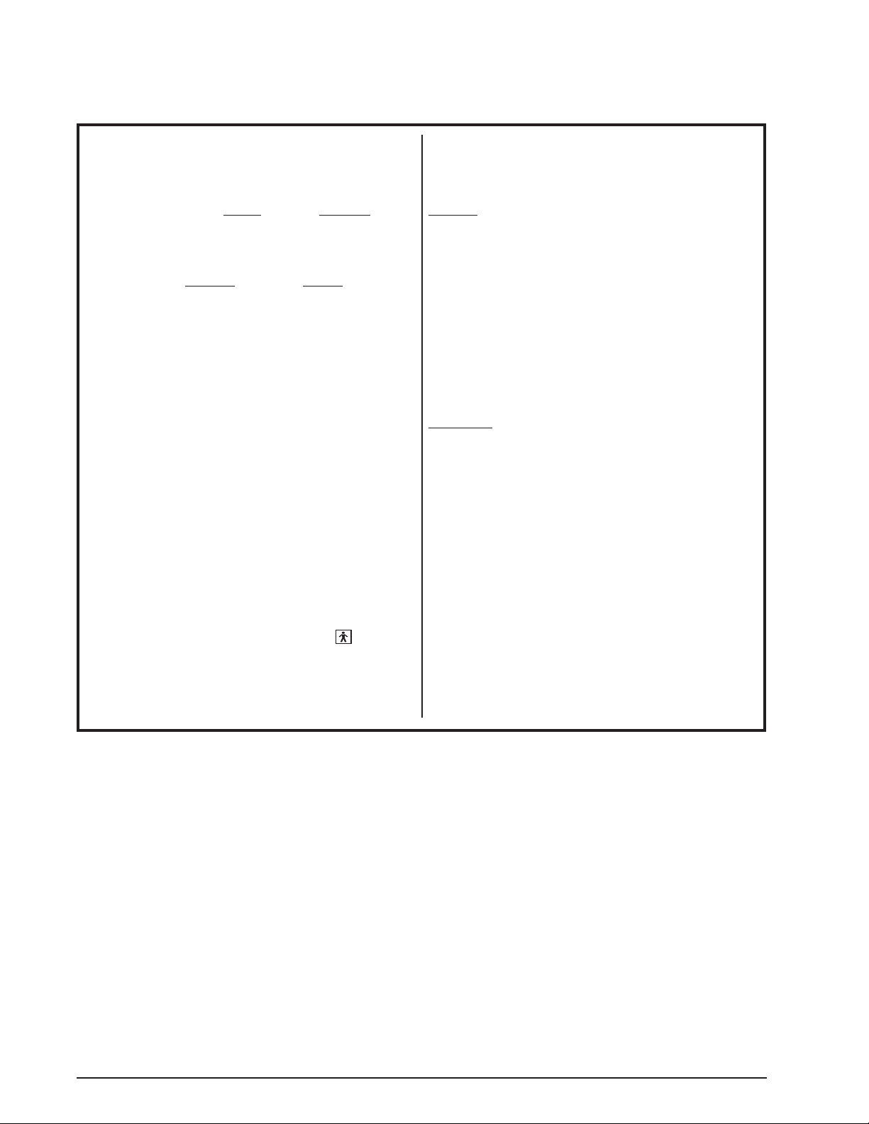
touch screen is not activated for 10 minutes, the system will go into screen-saver
mode (floating icon). If it is still not activated for another 15 minutes then it will
go into standby mode (blank screen).
- While system is in screen-saver mode or normal mode, pressing the standby
switch sets the system to standby mode.
- While in standby mode, pressing the standby switch returns the system to
normal mode without going through the boot-up sequence.
- While in screen-saver mode, tapping the touch screen or footswitch returns the
system to normal mode.
- On systems 685-0000-502 and above (see REF number on label), pressing and
holding the standby switch for 7 seconds then releasing will reset (reboot) the
system.
•
Speaker
Used to signal the acquisition of readings. A beep is emitted each time a reading
is stored. In Pachymetry S-Auto mode, a voice confirmation of the acquired
measurement value is provided. Audio feedback mode provides the user with
feedback of signal integrity.
•
Internal Printer
The current screen or a full report of the patient data can be printed on the internal
printer.
•
Probe Holders
The console contains probe holders on both sides of the viewing screen to hold
Pachymetry probe on one side and Biometry probe (with or without sleeve) on the
other side.
•
Stylus
Above the touch screen is a hole used to store the plastic stylus. Either the stylus
or your finger can be used to select a function or to enter data.
CAUTION
Do not use a sharp object in place of the stylus as it may damage the touch
screen.
2.2 8065750127
Page 35

OcuScan
24V
101010 BIO PACH
101010
BIO
PACH
24V
®
RxP Measuring System
Rear Panel
The rear panel contains the power input connector and connectors to interface with
system accessories (see Figure 2-2). Labels on the rear panel identify each of the
components, and also warn the operator of possible dangers.
Rear Panel Components
•
Power Input Connector
+24 VDC power enters the rear panel through an 8-pin din connector.
•
External SVGA Video Output Connector
The system provides a standard SVGA output connector for an optional monitor.
•
Footswitch Connector
The footswitch connects to this Mini Din connector.
•
Ethernet Connector
The Ethernet interface on the rear panel is used for network connection.
•
USB Connector
The USB bus connection is used to store and retrieve patient data to and from a
PC.
•
RS232 Connector
RS 232 serial communication connects the system to an external PC for service
use.
•
Biometry Probe Connector
Use this connector to plug in the Biometry probe.
•
Pachymetry Probe Connector
Use this connector to plug in the Pachymetry probe.
Figure 2-2 REAR PANEL - The rear panel contains a variety of connectors used to
connect power, handpieces, the footswitch, and accessories.
8065750127 2.3
Page 36

OcuScan
Carrying Handle
Eye Model
Flash Card Slot
Flash Card
®
RxP Measuring System
Flash Card Slot
The side panel contains a flash card slot where a Compact Flash card can be inserted
for storing patient data or upgrading the system software (see Figure 2-3). The
OcuScan® RxP Measuring System is a computerized machine that operates under
software control. If and when software upgrades are required, the new program can
be installed into the system through the use of a Compact Flash card. For instructions
on installing software upgrades, refer to "Installing Optional Software and Upgrading
System Software" in Section One of this manual.
Eye Model
In the base of the console, behind the touch screen, is a contact-type eye model used
for the probe check (see Figure 2-3). A probe check determines system functionality
and tests probe strength by measuring the Eye Model axial length. The eye model
is designed to display traces to simulate peaks for contact cornea, anterior of lens,
posterior of lens, and retina with a triangular shape simulating the sclera. Refer to
Section Three: Probe Check for a detailed description on how to perform a probe
check.
2.4 8065750127
Figure 2-3 SIDE PANEL - The left side of the
contains the Flash Card slot. Compact Flash cards are memory devices
that can be used to save patient data or upgrade the system software.
OcuScan
®
RxP Measuring System
Page 37

OcuScan
Footswitch
®
RxP Measuring System
Footswitch
The footswitch allows hands free initiation of the system control function.
Figure 2-4 FOOTSWITCH - The
OcuScan
®
RxP footswitch plugs into the rear panel.
Biometry Footswitch Functions
• Automatic Mode - To obtain biometry measurements in automatic mode, press
and hold the footswitch while aligning the probe on the eye until the desired
waveform or trace is obtained. It may be necessary to adjust the gain to obtain
an acceptable waveform. At this point hold the probe steady and release the
footswitch to obtain ten automatic measurements.
If the measurement is not locking (possibly due to one of the signal amplitudes
not meeting the required criteria), pressing and releasing the footswitch within
0.5 seconds will Force Freeze the measurement. After ten readings are obtained,
the gates are automatically placed on the echograph, and the measurement is
displayed in the reading box.
The user can also move through the measurements by pressing and releasing the
footswitch. Once a measurement is selected, holding the footswitch for 3 seconds
will delete that measurement. When a measurement is deleted the system will go
into Running-Saving state to acquire a new measurement. The above process can
be repeated to delete and retake additional measurements one at a time.
• Manual Mode - To obtain a measurement, press and release the footswitch
to activate the ultrasound. Place the probe on the eye and, when the desired
waveform is displayed, press and release the footswitch to save the measurement.
The operator can repeat this procedure nine more times, at which time gates are
automatically placed on the echograph, and the measurement is displayed in the
reading box.
8065750127 2.5
Page 38

OcuScan
®
RxP Measuring System
Pachymetry Footswitch Functions
• Automatic Mode - In automatic mode, a thickness measurement is initiated by
pressing a position button on the Pachymetry scan screen or by pressing and
releasing the footswitch. The position button will start blinking indicating that
the system is ready to take a measurement. In Map 1 or 2, hold the Pachymetry
probe perpendicular to the cornea at the position that corresponds to the position
button. The system will take a reading then move to the next location and start
blinking indicating that it is ready for the probe to be placed at that location.
After the system acquires the thickness readings for several positions, pressing
the footswitch deletes the previous position's value. The position button will start
blinking indicating that it is ready to acquire new data for that position.
In Single Point, quickly pressing and releasing the footswitch will step back
through the measurements. A selected measurement starts blinking and turns pink
if the user does not press the footswitch again within 3 seconds. Pink readings
are deleted and new measurements can be taken. If the user has pressed the
footswitch within 1 second, then the blinking would move to the previous location
without turning the current location to pink. After all the configured readings
have been taken for one eye (OD), pressing and holding the footswitch 5 seconds
selects the other eye (OS). When the system has switched to the other eye,
pressing and releasing the footswitch will cause the 1st position to start blinking
indicating that the system is ready to take the measurement.
• Manual Mode - In Manual mode, the position button starts blinking by pressing
the footswitch. Holding the probe perpendicular on the corneal position displays
the current thickness. Pressing the footswitch locks the reading for that position
and advances to the next position.
2.6 8065750127
Page 39

OcuScan
Applicator
Straight Probe
Angled Probe
®
RxP Measuring System
Probes and Probe Holders
®
The OcuScan
RxP Measuring System comes with probe holder cradles on each side
of the viewing screen where the Biometry and Pachymetry probes are placed when
they are not being used. The holder for the Biometry probe is on the right side of the
monitor while the Pachymetry probe the holder is on the left.
Three methods of using the Biometry probe can be employed (see Figure 2-5). It can
be held with or without its applicator for contact scans, it can be removed from its
applicator for immersion scans, or it can be removed from its applicator and placed in
a slit lamp adapter.
Figure 2-5 BIOMETRY PROBE - Three methods of using the biometry probe are
employed in biometry. In the upper illustration the probe is inserted into
its spring-loaded applicator. This applicator applies a consistent light
pressure to the cornea for scanning. In the lower illustration, the probe
is removed from its applicator and can be placed in a slit lamp adaptor
or used in an immersion shell.
Figure 2-6 PACHYMETRY PROBE - The optional Pachymetry probe fits comfortably
into the operator's hand for effortless corneal thickness measurements.
Two models are available: straight and angled (45°).
8065750127 2.7
Page 40

External Power Supply
Connector from power source plugs
into this end of power supply
DC voltage connector plugs into
rear panel of the system
DC voltage connector plugs into
rear panel of the system
Connector from power source plugs
into this end of power supply
POWER SUPPLY (PCM80PS24) POWER SUPPLY (PMP130-14-S)
OcuScan
®
RxP Measuring System
The
OcuScan® RxP Measuring System is powered by one of the two external,
universal power supplies shown in Figure 2-7. These supplies provide a DC voltage
of 24 V, and a minimum of 3.3 A to the console. They require a steady state input
voltage in the range of 100-120/200-240 VAC, 2 A at 50/60 Hz. These are autoranging power supplies that automatically adjust to any voltage within the range.
NOTE: The power cord used to connect the power supply to the wall outlet is
shipped with systems for use in the U.S.A. and Canada only. For other countries,
a power cord with appropriate ratings and national safety agency approval must
be used.
Figure 2-7 EXTERNAL POWER SUPPLY - The
OcuScan
®
RxP Measuring System is
powered by an external power supply.
2.8 8065750127
Page 41

OcuScan
®
RxP Measuring System
KEYBOARDS
When entering data into the various data fields, the system will display a keyboard on
the touch screen as shown in Figure 2-8. The first keyboard shown is the default with
lowercase letters. The following keyboards are displayed when the circled keys are
tapped on the touchscreen.
Figure 2-8 KEYBOARDS DISPLAYED ON THE TOUCHSCREEN - Four keyboards are
available to enter patient data.
8065750127 2.9
Page 42

OcuScan
®
RxP Measuring System
THIS PAGE INTENTIONALLY BLANK
LAST PAGE OF SECTION
2.10 8065750127
Page 43

OcuScan
MAIN MENU
PROBE CHECK
Verify that each probe
is functioning properly.
PACHYMETRY
(if option is ins talled)
Perform corneal
thickness measurements.
Scan
Scans for 25 points,
single point, or Lasik.
BIOMETRY
Perform axial length
measurements.
Scan
Biometry
Settings
Three modes available:
Manual, Auto, S-Auto
In the scan screen, tap
the Settings button to
customize the scanning
parameters.
Pachymetry
Settings
In the scan screen, tap
the Settings button to
customize the scanning
parameters.
Patient
Information
In the scan screen, tap
the Patient button to
enter patient data.
Details
A detailed table of ten
measurements per eye
is displayed.
IOL Calculations
IOL power options are
displayed based on
selected formulas.
Comparison
Compare IOL calculations
with five formulas for three
selected IOL's.
Formula Configure
Uses IOL Calculation
Formula based on the size
of the eye.
PATIENT
RECORDS
Manage patient data.
SYSTEM SETUP
Customize the system
to meet your specific
needs.
®
RxP Measuring System
INTRODUCTION
SECTION THREE
OPERATING INSTRUCTIONS
This section of the manual is written to help you learn to operate the
OcuScan® RxP
Measuring System. The operating instructions are written with the assumption that
you have no previous experience with the OcuScan® RxP Measuring System and
start at system power up then continue on through System Setup, Biometry Presets,
Patient Information, and finally Biometry Scans. If the optional Pachymetry software
is installed, instructions are also given for pachymetry setup and scanning. The
following flowchart shows the structure of the OcuScan
®
RxP software and gives you
an overall view of how to navigate in the system.
NOTE: Pachymetry is an optional item that must be ordered in addition to
the standard Biometry function. See Section Six: Accessories and Parts for
information on ordering the Pachymetry option.
8065750127 3.1
Figure 3-1 FUNCTIONAL FLOWCHART - This flowchart shows the sequential functions
of the
OcuScan
®
RxP Measuring System.
Page 44

OcuScan
®
RxP Measuring System
SYSTEM POWER-UP
When power is applied to the system, a power-up screen appears containing the
OcuScan® RxP logo. During the power-up state the system performs self-tests for
about three seconds. If any of the self-tests fail, a message appears on the bottomhalf of the screen to notify the user. If the self-test failure is a prompt, the user can
continue after acknowledgment by pressing the OK key. If it is a system failure, the
user cannot transition out of the screen. After successfully completing the self-tests,
the Menu screen appears.
It is not necessary to turn the system OFF. A “
Screensaver” mode is activated after
the screen and footswitch have been inactive for ten minutes. Figure 3-2 shows the
screensaver display. Tapping the screen will deactivate the screensaver. If the system
is inactive for another 15 minutes after entering screensaver mode, the system enters
the standby mode (or sleep mode) and the screen will go blank. Standby mode can
also be entered by pressing the Standby switch on the front panel.
System Reset
Systems with REF number 685-0000-502 can be reset by holding the Stand-by switch
for 7 seconds or longer then releasing it. These actions will restart the system as in the
power-up cycle.
Figure 3-2
3.2 8065750127
OCUSCAN
appears after the system has been inactive for ten minutes.
®
RxP SCREENSAVER DISPLAY - The screensaver display
Page 45

OcuScan
®
RxP Measuring System
The Menu Screen
From the Menu screen the user may go directly to the Biometry screen (or optional
Pachymetry screen if installed). Alternatively, the user may elect to view the System
Setup screen, Patient Records, or the Probe Check screen.
Figure 3-3 MENU SCREEN - After the system transitions to the Menu screen the user
Using the Touch Screen
The
OcuScan® RxP Measuring System uses a touch screen user interface with the
system. The stylus provided with the system is the recommended tool to use when
touching the screen to make selections. A holder is located at the top of the system to
conveniently store the stylus. Selections are made by lightly tapping the stylus on the
screen.
can choose from the selections shown here (shown with Pachymetry
option installed).
8065750127 3.3
Page 46

OcuScan
Clinic:
Tapping the clinic field
displays a keyboard that
allows a clinic name to
be entered. Used in Full
Report printout and on
PC Patient Viewer
program.
Default Operator:
This drop-down menu
allows the user to select
from five operators
identified in the operator
name field.
Operator Name:
The name of each
operator is shown here.
Tap the field to enter the
name of the operator.
Records:
These buttons
determine the action
of the Print/Save
button.
Printer Paper:
Use these buttons to
load printer paper, or
move it forward or
reverse.
Save Patient Format:
Selection allows saving
patient data in Compact
Flash or PC Format. Only
the selected format will be
displayed on Patient Records.
OK:
Tapping this button saves
changes made to system
setup.
Esc:
Exits the system
setup without saving
changes.
Service Menu:
Entrance to Service
Mode-password required.
Video Mode:
Select LCD Only,
or SVGA mode
to connect to an
external monitor.
Display Brightness:
Adjustable between
10 and 100.
Language:
Drop down menu
allows the user to
select from seven
languages.
Date and Time:
Select the desired
format, then enter
the correct values.
Print/Save Button:
Tapping this button will
print a copy of the System
Setup screen.
®
RxP Measuring System
SYSTEM SETUP
The first time a new system is powered up it is important to configure it with your
local information (date, time, etc.). To fill in the System Setup data, follow the
instructions below.
1 With the external power supply plugged into a power plug (110-120/220-240
VAC), and its 24 VDC cable plugged into the
OcuScan® RxP rear panel, the
system will automatically turn on. (For systems using power supply PMP130-14-S,
press the toggle switch on the power supply to turn the system on.) The Power-Up
screen appears and an LED illuminates in the middle of the standby switch button
®
to indicate that power is turned ON. After the OcuScan
RxP Measuring System
performs a quick system self-test, the Menu screen appears on the display monitor
(see Figure 3-3).
2 From the Menu screen select
3 Using the stylus, touch the Clinic box; a keyboard appears on the screen. Using
3.4 8065750127
System Setup.
Figure 3-4 SYSTEM SETUP SCREEN - The System Setup screen enables the user to
configure the system as needed. This screen is also used to load paper
in the internal printer.
up to 20 characters, type the name of your facility, then press OK. The name of
your facility appears in the Clinic box.
Page 47

OcuScan
®
RxP Measuring System
4 Select the Operator number from the drop down menu, then enter names for up to
five operators. To enter a name, touch the text box next to Default Operator and
a keyboard appears on the screen. Using up to 20 characters type the name, then
press OK. Press the Default Operator arrow until the desired number (1 to 5) is
reached.
5 In the
Date field, select the Format you desire to have the date displayed in from
the following list, then select the current Day, Month, and Year.
• MON/DD/YYYY - the month is shown alphabetically (JAN, FEB, etc.), the
day and year numerically.
• DD/MON/YYYY - the day is shown numerically, the month alphabetically,
and the year numerically.
• MM/DD/YYYY - the month, day, and year are shown numerically.
• DD/MM/YYYY - the day, month, and year are shown numerically.
6 In the Time field, select the
Format you desire to have the time displayed in, then
select the current Hour, Minute, and Second.
7 In the
Language field select the language you desire on the information screens.
8 The Video Mode field contains two selections in the drop down menu: LCD Only,
or SVGA. Use the SVGA selection to enable the output to an external video
monitor in addition to the LCD. If an external SVGA monitor is not used, it is
recommended to select LCD only mode.
9 In the
Display Brightness field adjust the optimum video brightness level for the
room environment.
8065750127 3.5
Page 48

OcuScan
®
RxP Measuring System
The Records field contains two buttons that set the action of the Print/Save button
that is displayed in most of the working screens. Pressing the top button toggles
The Print/Save
Button
through the following options:
Display menu - Displays the options window shown in Figure 3-5.
•
Full Report and Save - Prints a full report (see Figure 3-6) and saves the data
•
to the current patient's records (if a Compact Flash card is inserted).
•
Current Screen - Prints the current screen only.
Full Report - Prints a full report for the current patient.
•
10 Press and release the top button in the Records field to cycle through the options.
Stop on "Full Report" or "Full Report and Save."
When “Full Report” or “Full Report and Save” have been selected, the Define
Report button becomes active. Pressing the button opens a window that allows the
user to select which items shown in Figure 3-5 will be printed each time the print
button is pressed.
When saving a file that has already been saved, the system will provide the
following options:
• Overwrite the existing files - overwrites patient's file with new data created
since the last save.
• Save as new file - Saves data in a new file and adds an extension number to the
name. For example: file named 007 will be saved as 007-1.
• Esc - returns to the previous screen without saving data.
Figure 3-5 DISPLAY MENU AND DEFINE REPORT POP UP WINDOWS - Choosing Display Menu
from the Records selections allows instant access to the Print pop up window when the
Print/Save button is pressed. The Define Report window allows you to select the specific
data to be printed.
3.6 8065750127
Page 49

1 24.17
2 24.18
3 24.17
4 24.17
5 24.17
6 24.17
7 24.17
8 24.17
9 24.17
10 24.17
AC: 3.94
L: 4.48
V: 15.75
SD: 0.00
Avg: 24.17
10/20/2005
Operator: Johnson
06:31 V1.12
Patient Name: JONES, PAT
ID: 143262645
Age: 52
Biometry Preset: Dr. Smith
Pachymetry Preset: Dr. Smith
Type: Phakic
AC: 1532 L: 1641 V: 1532
K1: 43.00
K2: 43.50
K: 43.25
K1: 43.00
K2: 43.50
K: 43.25
Avg AL: 24.17 SD: 0.00
AC: 3.89
White To White:
Technique: Immersion
Mode: AUTO
Gain: 64
TA: -0.5
IOL: MA30AC P
Formula: SRK-T
A: 118.40
OS/Left Eye
OS/Left Eye
Emmetropia: 18.85
IOL Power Refraction
17.50
18.00
18.50
19.00
19.50
20.00
20.50
21.00
21.50
0.92
0.58
0.24
-0.10
-0.45
-0.80
-1.16
-1.52
-1.88
C1 C2 L1 L2 R
1mm 11mm 21mm 31mm 41mm
FROZEN
1st 2nd 3rd
IOL: MA60BM P
Formula: SRK-T
A: 118.90
Emmetropia: 19.40
IOL Power Refraction
18.00
18.50
19.00
19.50
20.00
20.50
21.00
21.50
22.00
0.93
0.60
0.27
-0.07
-0.41
-0.75
-1.10
-1.45
-1.80
IOL: MTA4U0 A
Formula: SRK-T
A: 115.30
Emmetropia: 15.92
IOL Power Refraction
14.50
15.00
15.50
16.00
16.50
17.00
17.50
18.00
18.50
1.11
0.73
0.34
-0.06
-0.46
-0.87
-1.28
-1.69
-2.11
X
MISSION HOSPITAL
OcuScan
®
RxP Measuring System
Figure 3-6. FULL REPORT PRINTOUT
The Full Report depends upon
measurements taken and K values
entered. Data must be present in
order for a report to be printed. If
measurements were taken then the
printout will contain most of the Scan
screen information. The Calculation
screen is printed if K values were
entered. Pachymetry screens are
printed if pachymetry measurements
were taken for the same patient.
This figure shows a printout of the
Full Report for a patient who had
measurements taken for the left eye
only. K values were entered so the IOL
Calculation screen was also printed
showing the various selections of IOL's
and formulas used.
8065750127 3.7
Page 50

OcuScan
®
RxP Measuring System
11 Tap the drop down menu in the Save Patient Format field and select the default
format for saving patient data - Compact Flash or PC Format.
NOTE: The format selected in the System Setup screen determines what
files appear in the Patient Records screen. For example: if PC Format is
selected, then only those files saved in PC Format are displayed. If Compact
Flash format is selected, then only files saved in Compact Flash format are
displayed.
Compact Flash (Binary)
The Compact Flash format should be used when saving patient data for backup
purposes. Files in this format cannot be viewed on a PC. The advantage of
this format is that it maximizes the number of patient files that can be saved
to a Compact Flash card. For example, a patient file containing biometry and
pachymetry data for both eyes will have a file size of approximately 70 KB.
Therefore a 128 MB Compact Flash card can hold a minimum of 1800 patient
files saved in this format.
PC Format (Excel)
This format allows you to view the patient data on a Personal Computer (PC)
using a Patient Viewer template that is included on the CD provided with the
system. The file size is about twice the size of the Compact Flash file therefore
only half as many patients can be stored on the Compact Flash card in this format
as compared to the Compact Flash (binary) format.
For additional information, refer to
Copying Patient Data to a Personal
Computer.
12 Press
OK to accept the changes and return to the Menu screen. Pressing the Esc
key exits the System Setup screen without implementing any changes and returns
to the Menu screen.
NOTE: The Service Menu is intended for use by service personnel only,
therefore, a password is required to enter that area.
3.8 8065750127
Page 51

OcuScan
®
RxP Measuring System
PATIENT RECORDS SCREEN
The Patient Records screen shown in Figure 3-7 allows the user to manage and select
patient data. It is used to:
• Display patients currently saved to the Compact Flash card (if inserted).
• Sort the patients by identification number, last name, or first name.
• Remove a patient from the database.
NOTE: The Patient Records screen only displays patient records saved in the
currently selected Patient Format in the System Setup screen. For example: if
PC Format is selected, then only those files saved in PC Format are displayed. If
Compact Flash format is selected, then only files saved in Compact Flash format
are displayed.
The following actions are available by tapping the associated buttons on the patient
records screen.
• Select - Loads the selected patient record, i.e., that patient becomes the current
patient. Refer to "
Uploaded Patient Data
" for additional information.
• Esc - Exits the patient records screen without loading a patient.
• Delete - Deletes the selected records.
• Refresh - Updates the Patient table. This action is required when a different Flash
card is inserted.
• Ident - Sorts the records by identification number.
• Last Name - Sorts the records by last name.
• First Name - Sorts the records by first name.
NOTE: When patient data is retrieved from storage, it displays only the patient
data and measurements. IOL power calculations will depend on current selection
of IOL's, formulas, and Target ametropia.
To select a patient, tap the desired patient entry with the stylus and it will be
highlighted. To add new patients, refer to
Figure 3-7 PATIENT RECORDS SCREEN
Tapping the Patient Records button on the
main menu displays this screen. The user
can select, sort, remove patient records,
or refresh the listing from here.
The Patient Records screen only displays
patient records saved in the currently
selected Patient Format in the System
Setup screen. For example: If PC Format
is selected, then only those files saved in
PC Format are displayed. If Compact Flash
format is selected, then only files saved in
Compact Flash format are displayed.
Patient Setup for Biometry and Pachymetry.
8065750127 3.9
Page 52

OcuScan
®
RxP Measuring System
Uploaded Patient Data
Uploaded patient data is data that was previously saved to the Compact Flash card
then uploaded back into the system for viewing. Uploaded patient data has the
following characteristics:
• System settings that were saved along with patient data will be loaded back into
the system.
• All up-loaded settings as well as measurement data will be highlighted in yellow
and will only be highlighted on screens that have data.
• All fields in the Patient Information screen except Patient ID can be modified.
• If a setting is changed, a pop-up message is displayed warning the user that the
current patient measurements will be deleted. If the new setting is accepted by
tapping the checkmark, the software will reload the current system settings (last
setting selected before upload), make the requested setting change, and restore the
original default color. NOTE: System settings are changed in the Biometry and
Pachymetry Presets screens.
• After a patient upload, the user can only delete all the measurements for an eye
and not individual ones.
• Date and time when the patient records were last saved are shown.
3.10 8065750127
Page 53

OcuScan
®
RxP Measuring System
PROBE CHECK
A probe check determines system functionality. For biometry, the probe check
tests probe functionality by measuring the Eye Model axial length. The eye model
is designed to display traces to simulate peaks for contact cornea, anterior of lens,
posterior of lens, and retina with a triangular shape simulating the sclera.
Biometry Probe Check
1. From the Main Menu, tap the Probe Check button. The following message
appears, "By entering any of the following options all patient data will be erased."
If you have a current patient with unsaved data, tap the Esc button to go back and
save the data then return to the probe check.
2. Tap the OK button to advance to the probe check.
3. Tap the Biometry button to select the biometry probe check. The biometry probe
check screen appears as shown in Figure 3-8.
4. Verify that Technique is Contact. If not, tap the Settings field and select Contact
mode to measure the eye model located at the back of the system.
5. Dip the tip of the biometry probe in water then place it on the eye model located
at the rear of the system. Note: Other eye models may give results different
from those stated here.
6. Select Auto mode.
7. Press the footswitch and wait for the system to take 10 readings.
8. Verify that the echogram has four strong echos representing the cornea (C1), front
of the lens (L1), back of the lens (L2), and the retina (R).
Figure 3-8. BIOMETRY PROBE CHECK SCREEN - This screen is used to verify that
the biometry probe is functioning properly.
8065750127 3.11
Page 54

OcuScan
®
RxP Measuring System
Pachymetry Probe Check
1. From the Main Menu, tap the Probe Check button. The following message
appears, "By entering any of the following options all patient data will be erased."
If you have a current patient with unsaved data, tap the Esc button to go back and
save the data then return to the probe check.
2. Tap the OK button to advance to the probe check.
3. Tap the Pachymetry button to select the pachymetry probe check. The pachymetry
probe check screen appears as shown in Figure 3-9.
4. Select Auto mode (if system is not in Auto mode already) and the 300-1100 range
for the eye model at back of system.
5. Place a thin layer of water on top of the eye model then position the pachymetry
probe perpendicular to the top surface of the eye model.
6. Press the footswitch and wait for the system to take all the configured readings for
one eye. Note: The probe must be perpendicular to the eye model in order for
the system to detect a valid reading.
7. Verify that the system takes a measurement for each scan # and all readings are
relatively close to each other. NOTE: A slight tilt of the probe may cause a
larger Standard Deviation (SD).
Figure 3-9. PACHYMETRY PROBE CHECK SCREEN - This screen is used to verify
that the pachymetry probe is functioning properly.
3.12 8065750127
Page 55

OcuScan
Presets:
Five presets are available
to be configured as needed.
Phakic Eye Velocities:
Changes to the standard
phakic eye velocities can
be made here.
Settings:
Select desired setting
from each drop down
menu. Each selection
is applied to the current
preset.
Sequence:
This selection determines
the sequence of screens
used during the Biometry
procedure. Once the
sequence is selected,
the user can move
through the procedure
using the arrow keys.
Pseudo IOL
Defaults:
Selecting an entry and
tapping Edit opens
an edit window where
values can be changed.
Lens Constants:
Displays the Lens
Constants screen.
Keratometer Index:
Available in the Haigis
formula option only.
Acquisition Speed:
Three speeds are available:
Low, Medium, & High
Validation:
See Validation Menu
below.
Name:
Enter Preset name.
Phakic IOL Defaults:
Selecting an entry and
tapping Edit opens
an edit window where
values can be changed.
Age compensation:
Must be set ON to
enable Age based
velocity compensation
for the natural lens.
Validation Menu:
Tapping the Validation Setup
button displays the menu on the
right. The user can activate any
of the 12 validation points which
will display a message if
validation is turned ON and the
selected criteria is met.
Audio Feedback:
A beep-based feedback signal that
increases in speed as the quality of
acquisition improves.
®
RxP Measuring System
BIOMETRY
SETTING UP THE BIOMETRY PRESETS
The system allows up to five different preset configurations enabling the user
to quickly select a particular setup for a patient based on eye type or surgeon
preferences. The following steps show how to change and save a preset.
1. From the Menu screen, tap the Biometry button to enter the Biometry scan screen.
2. Tap anywhere in the Settings frame. The Biometry Presets screen appears as
shown below in Figure 3-10.
Figure 3-10 THE BIOMETRY PRESETS SCREEN
This screen allows the user to configure five
different presets to select from when preparing for
a biometry scan.
8065750127 3.13
Page 56

OcuScan
®
RxP Measuring System
3. Tap the Preset down arrow to display the drop down menu. Five presets are
available and each can be selected by tapping on the number.
4. Tap the Name field. If desired, enter a name for the preset using the keyboard
displayed on the screen. Confirm the name by tapping OK.
Settings
The Settings frame contains selections to set the defaults for Mode, Technique,
Volume, Gain, and Target Ametropia. The user can also select Audio Feedback, Age
Compensation, Velocities for phakic eye, Acquisition Speed, and Validation. When
a new patient is initiated in the patient screen, the defaults from the selected Setting
are automatically activated, although Mode and Gain can be manually changed on the
Scan screen.
5. Tap the
Mode drop down menu (down arrow) and select the desired mode.
The Mode setting has three options: Manual, Auto, or S-Auto (Super Auto). The
factory default is set as Auto.
Manual - In this mode the user unfreezes the system by pressing and releasing
the footswitch, positions the probe on the eye, and looks for a good waveform.
When a desired waveform is seen, the footswitch is pressed and released to save
the measurement. Software criteria requires a minimum of cornea and retina
peak detection to save the reading under Force Freeze condition. Force Freeze
measurements are shown in smaller font and blue color.
Auto - In this mode press and hold the footswitch, align the probe to get the
best waveform and release the footswitch. If the software criteria for range and
amplitude of peaks is met, then the system will automatically obtain ten readings.
If there is difficulty in obtaining a measurement, the user can override the
software criteria by initiating a force save by pressing and releasing the footswitch
within a half-second. Force Freeze measurements are shown in smaller font and
blue color. The user should review the peaks and gate locations to decide to retain
or delete the Force Freeze measurements.
S-Auto - Super Auto mode is similar to Auto mode except that it automatically
adjusts the gain, and software criteria looks for beam perpendicularity.
6. Tap the Technique
drop down menu and select the desired technique: Immersion
or Contact. The default mode is Contact.
Contact - In the Contact technique, readings are obtained by placing the biometry
probe directly on the patientʼs cornea.
3.14 8065750127
Page 57

OcuScan
Immersion
Shell
Biometry
Probe
1.5 to 9.8 mm for auto-trigger
AC L
AL
V
®
RxP Measuring System
Immersion - In the Immersion technique, an immersion shell containing the
probe is placed on the patient's eye and filled with solution between the probe and
the cornea (see Figure 3-11). Since the probe is not touching the cornea, there is
an offset on the display between the peak from the probe tip and the peak from the
cornea.
Figure 3-11. IMMERSION TECHNIQUE - The probe tip must be located between 1.5 to
9.8 mm from the cornea in order for the system to automatically lock.
NOTE: In Biometry Immersion mode, the probe tip must be between 1.5 mm
and 9.8 mm distant from the cornea in order for the system to automatically
lock and freeze.
In Immersion mode the software criteria looks for C1 (anterior cornea) and C2
(posterior cornea). All other criteria for amplitude threshold and peak locations
are the same as for the contact modes.
7. Tap the Volume drop down menu and select the volume of audible feedback. The
selections are OFF, LOW, MEDIUM, and HIGH. The system default is low.
8. Tap the
Gain field. A window opens that allows you to select a new default Gain
setting for that preset. The allowable range is 40-80 dB with a system default of
64 dB.
9. Tap the Target Ametropia drop down box. The default for target ametropia
is 0.00. The other selections are -0.5, -1.0, and Other. If Other is selected, the
acceptable range is -10 to +10.
8065750127 3.15
Page 58

OcuScan
®
RxP Measuring System
Phakic Eye Velocities
The Phakic Eye Velocities frame allows you to change the ultrasound velocities for
the Anterior Chamber (AC), Lens (L), and Vitreous (V).
10. Tap the Age Compensation button to toggle it ON or OFF. If Age compensation
is enabled, the software automatically compensates the velocity of the natural
lens based on the age entry of the patient. Patient age is entered on the Patient
Information screen.
Age Compensation provides the appropriate ultrasound velocity for the crystalline
lens based on age of the patient. Velocity (V) is inversely proportional to the
square root of the Density (d) and the Compressibility (c) of the medium.
Compressibility is the fractional decrease in volume when pressure is applied to
the medium.
V= 1
dc
The greater the age of the patient, greater will be the thickness of the lens (greater
compressibility and density) and hence lower the ultrasound velocity1.
11. To change the AC, L, or V velocity, tap inside the field and enter the new velocity
in the dialog box. Tap OK to accept the new value. The acceptable velocity ranges
are as follows:
AC: 1400-2000 with factory default at 1532 m/s
L: 900-2750 with factory default at 1641 m/s
V: 300-3000 with factory default at 1532 m/s
Acquisition Speed
The Acquisition Speed setting has three selections (Low, Medium, and High) that
determine how fast measurements are acquired.
12. Tap the Acquisition drop-down menu and select the desire speed.
Validation
Tapping the Validation Setup button displays the Validation Menu shown in Figure
3-10. The user can activate any of the 12 validation points which will display a
message if validation is turned ON and the selected criteria is met. The measurement
in question should be repeated and possibly a second person should confirm it. For
example: If the first validation point for K < 40 is selected, then a pop-up asking
you to confirm the entry will be displayed if a K value less than 40 is entered. To
change the criteria for a validation point, simply tap in the field then use the on-screen
keyboard to enter the new value. Following is a list of 12 validation points:
Alerts user that the K value is possibly too low. Default limit is set to 40 D but
•
user can configure as appropriate.
Alerts user that the K value is possibly too high. Default limit is set to 47 D.
•
•
Alerts user of larger Kavg variance between eyes. Default limit is set to 1 D.
1
Jack T. Holladay, MD, MSEE, Standardizing Constants For Ultrasonic Biometry, Keratometry And Intraocular Lens Power Calculations.
JCRS 1997; 23: 1356-1370
3.16 8065750127
Page 59

OcuScan
®
RxP Measuring System
Alerts user when the Corneal Diameter is possibly too low. Default limit is set to
•
11 mm.
Alerts user when the Axial Length (AL) measured is possibly short. Default limit
•
is set to 22 mm.
Alerts user when the AL measured is possibly long. Default limit is set to 25 mm.
•
Alerts user to the possibility of staphyloma when it detects a long eye that
•
either has poor retina peak, standard deviation (SD) is too large, or there is wide
variance between the AL of the eyes. Default limit for AL is 26 mm, for SD is
0.10 mm and 0.33 mm for variance. User is advised to perform B-Scan Biometry
to confirm.
Alerts user of larger AL variance between the eyes. Default limit is set to
•
0.33 mm.
Alerts user of variability in AL for the same eye. Default limit for SD is set to
•
0.10 mm.
Alerts user of a large variance in IOL power between the eyes. Default limit
•
is 1 D.
Alerts user the possibility of probe not being perpendicular to the eye while some
•
of the measurements were being taken. User may want to retake some of the
measurements where some of the peaks are not of similar amplitude.
Alerts user of possibility of waveform saturation in some of the measurements.
•
User may want to reduce the Gain and retake the measurements that appear
questionable.
13. While Validation is ON, tap the Validation Setup button to open the Validation
menu. Select the desired options and change any of the values as necessary. Tap
Save to save the changes for that Preset (or Esc to exit without saving).
14. Tap the Validation ON/OFF button to toggle the selection for the desired state
(ON or OFF).
Audio Feedback
When Audio Feedback is on, the system emits a beeping sound that increases in speed
as the quality of the echogram during acquisition improves. Quality of acquisition
will improve as all the peaks needed to obtain the axial length increase in amplitude
but at the same time are not saturated. Optimum signal condition would result when
probe is held perpendicular to the eye with appropriate gain level that does not
saturate. Tapping this button toggles Audio Feedback ON or OFF.
Keratometer Index
This entry is used to accommodate the various keratometers that may be used in
acquiring the patient's K values. The acceptable range is 1.3315 to 1.3380. The
keratometer index should be listed in the keratometer's user manual. To change the
value, tap on the screen to display the edit window. This keratometer index entry will
only be used for Haigis formula (displayed only when Haigis option is installed). All
other formulas expect K values to originate from 1.3375 and therefore the index is
fixed at 1.3375 for those formulas.
8065750127 3.17
Page 60

OcuScan
®
RxP Measuring System
Sequence
The Sequence section allows you to set the sequence of screens that are displayed
when advancing through the biometry screens. The selections that are enabled (blue)
will be displayed when the Next screen (Arrow) button is pressed. When all the
selected screens have been displayed, the system loops back to the 1st screen. The
Patient Information and Scan screens are always enabled.
15. Select or deselect each screen as desired in the Sequence frame.
Pseudo and Phakic IOL Defaults
By selecting a material in the Pseudo or Phakic IOL Defaults list, you can modify the
name, velocity, and thickness of the selected material.
16. Select the material to be changed in the Pseudo or Phakic IOL Defaults list, then
tap the Edit button.
17. Tap inside the field to be changed, enter the new value, and tap OK to accept the
change.
Lens Constants
The Lens Constants screen shown in Figure 3-12 provides the user with the choice
of ten IOL's for each setting. The IOL's shown here will be a selection in the IOL
Calculation screen (see Figure 3-23) for calculating IOL power. Each entry can be
edited to match the user's preferred IOL values. The A0, A1, and A2 entries are used
in the optional Haigis formula only and will not be displayed if the Haigis option is
not installed. The factory defaults used for A Constant is from the lens manufacturer's
specifications.
18. Tap the Lens Constants button. The Lens Constants screen appears as shown in
Figure 3-12.
19. Tap one of the rows in the Lens Constants table. The row number appears and
fields for all entries can be edited. Press OK to confirm the new values, Esc to
return to the Lens Constants screen without saving the changes, or the Trash
button to delete an entry.
All the three constants A, ACD, and SF must be entered when a new IOL is added
or modified. Refer to Table 1-5 for IOL constants. The Reset button allows the
user to reset the selected row to the factory default IOL and its constants.
NOTE: If the Haigis option is installed then A0, A1, and A2 will also be reset.
When any of the IOL's in the Lens Constant screen are edited, the designation in the
I/U/C column changes from I (Initial) to U (User Change). When constants are
calculated using postoperative data in the Lens Constant Update screen, it changes to
C (Calculated)
3.18 8065750127
Page 61

OcuScan
Lens Parameters:
Tap on a row of values
to display the edit box.
Tapping on the Reset Button
will restore the factory default
IOL and its constants.
Columns A0, A1, and A2
apply to Haigis formula only
and will be displayed only if
the Haigis formula is installed.
®
RxP Measuring System
20. Tap the Lens Constant Update button. The Lens Constant Update screen appears
Lens Constant Update Screen
The Lens Constant Update Screen enables the user to customize the A, ACD, and SF
The Lens Update Screen displays the name of the lens for which the constants are
Figure 3-12. LENS CONSTANTS SCREEN - This screen allows the user to make changes
to the default values used for the lens constants.
as shown in Figure 3-13.
constants using the patient's preoperative and postoperative data for any of the ten
stored lenses on the selected Doctor Settings Screen. The A constant is used in the
SRK-T and SRK-II formulas, SF is used in the Holladay formula, and ACD is used
in the Binkhorst-II and Hoffer-Q formulas. Although the system will compute the
constants based on a single patient case, a minimum of twenty patient cases should
be used in order to achieve higher statistical significance in the prediction of new
constants. The system will accept up to fifty patient cases. NOTE: Use pre-op data
for K1, K2, and AL, and post-op data for SPH and CYL.
being changed along with its constants. To select a lens tap the drop down menu
beside the lens name, then tap on the desired lens.
8065750127 3.19
Page 62

OcuScan
Lens Data:
Tap on a row to display
the Add data window.
Select lens
®
RxP Measuring System
Touching any row of the grid will open the Edit screen or Add screen depending upon
Parameter Range
K1 28 D (12.05 mm) to 62 D (5.45 mm)
K2 28 D (12.05 mm) to 68 D (4.96 mm)
AL 15 to 39 mm
SPH -15 to +15 D
CYL -15 to +15 D
V 0 to 30 mm
IOL -50 to +50 D
When (SPH + (CYL/2) ) < -4, or when (SPH + (CYL/2) ) > +4 , the system will
Figure 3-13. LENS CONSTANT UPDATE SCREEN - Lens constants can be updated
here based upon actual patient data.
whether the row has data to edit or it is a new entry. The following parameter ranges
are allowed:
require entry of the V (Vertex Distance) parameter, or verification of the default value
of V = 12 mm. For each line of IOL implant data that does not require entry of the
V parameter, one SF value is automatically calculated. To use the default value of
Vertex V=12 mm, press the Enter key. If a new value is desired, delete the default by
pressing the Backspace key and typing in the new number.
3.20 8065750127
Page 63

OcuScan
®
RxP Measuring System
As data is entered for each case, its SF value is calculated and displayed in the
SF column. If SF is less than or equal to 3.10, or more than or equal to 5.10, it is
considered as NULL (indicated by the N in the EXCL column) and is excluded from
the calculation of the average SF.
After the data entry, the system calculates the following information if the
Compute
button is pressed.
• Average Value (AVR) and Standard Deviation of the Mean (SEM) for each
parameter K1, K2, AL, SPH, CYL, and IOL.
• AVR of Surgeon Factor column.
• New calculated constants A and ACD corresponding with calculated SF value.
These are displayed below the current constants for the selected lens, and the
Identifier I/U/C is changed to C (Calculated).
• Number of cases used for calculations, as well as the number of exclusions and
SEM.
Note: As AVR is calculated, the system excludes the cases in which SF is
outside the maximum and minimum ranges, as determined by the formula
(SF
+/- 2*SD). If any cases are excluded for this reason, "X" is displayed
avg
in the EXCL column.
The
Update button updates lens information for the selected lens in the current Preset
only and the lens will be labeled as "C" for Calculated. The Clear button clears data
from the Average and SEM rows. The OK button returns the system to the Lens
Constants screen.
NOTES:
Do not select the Compute option unless you have actually entered and verified
the appropriate values into the LENS UPDATE screen. Before Updating,
compare the current constants to the calculated constants to ensure that you
want to replace the current constants with the calculated ones. Pressing the
Update button will store the new (calculated) constants, and these will be
retained under the current Preset.
Consult with the IOL manufacturer if you are in doubt concerning which
constant to use in your IOL selection.
21. Return to the Biometry Scan screen by tapping OK at each screen. When OK
is pressed at the Biometry Presets screen, you will be prompted to save the
new settings for that preset; tap Yes (√) or No (X). NOTE: Currently unsaved
patient data will be lost if the new settings are saved.
8065750127 3.21
Page 64

OcuScan
®
RxP Measuring System
PATIENT SETUP FOR BIOMETRY
Patient information for both Biometry and Pachymetry is entered on the same screen
for both procedures if Pachymetry is performed in conjunction with Biometry (user
enters via Biometry selection). If user selected Pachymetry from the Menu screen,
then a different Patient screen with only Pachymetry related information is displayed
(see Pachymetry section).
1. From the Menu screen, tap either the Biometry or Pachymetry button to enter the
respective scan screen.
2. Tap the Patient frame as shown in Figure 3-14 to enter the Patient Information
screen.
Tap the Patient frame to enter the Patient Information screen.
Figure 3-14 THE PATIENT FRAME - Tapping this frame in the Biometry screen opens
the patient information screen.
The Patient Information Screen appears as shown in Figure 3-15. If a patient was
already displayed on the Biometry Scan screen, the same information will appear on
this screen. The current information can be changed or new patients can be entered
by tapping the New Patient button which will prompt you to save the current patient
(if one was displayed) then clear all the fields for the new data. Previously saved
patients can be selected from the patient list by tapping the Patient List button.
When the
New Patient button is pressed to enter a new patient, all settings that were
changed for the previous patient is returned to the default value. Settings that were
changed such as the Gain in the Biometry Scan screen are also returned to the default
value.
3. Tap the New Patient button. NOTE: Always start a new patient by first
activating new patient key. Do not manually erase the old patient data and
enter new patient.
4. Tap the Patient Name field. The large field is for the last name (20 character
maximum) while the smaller field is for the first name (3 character maximum).
A keyboard appears (see Figure 2-8) and a dialogue box that allows you to accept
or cancel the name entered.
3.22 8065750127
Page 65

OcuScan
New Patient:
Tap this button prior to
entering new patient
information.
Patient List:
Displays the Patient
List showing those
patients in the
currently selected
format; PC or
Compact Flash.
OD/Right EyeOS/Left Eye:
Adjustable parameters
for each patient. The
K Adjust button opens
the K Correction screen
where K values can be
calculated.
Patient Info:
Tap inside each field to input patient data.
A patient ID is required in order to save
patient data.
Presets:
Select the Presets for each patient
here. The Operator is setup in the
System Setup screen. The presets
are setup in their respective
preset screens.
Return Button:
Return to the scan
screen.
Print/Save Button:
Tapping this button
activates the action
selected in the
system setup.
SAVE Button:
Tapping this button saves the
patient to the Compact Flash
card in the format selected in
the System Settings screen.
To IOLCALC:
Tap this button to go to
the IOL Calculation Screen
®
RxP Measuring System
Figure 3-15 THE PATIENT INFORMATION SCREEN- New patients can be entered here
or current patient information changed.
5. Enter the last name of the patient by tapping the appropriate letters on the
keyboard displayed on the screen then tap OK to accept the name.
6. Repeat steps 4 and 5 for the first name, the Patient ID, and Age fields. If the Age
field is grayed-out, Age Compensation is turned off and can be turned on in the
Settings screen (see Setting up the Biometry Presets).
NOTE: A Patient ID is required to save patient data since it is used as the
filename when saved to the
Compact Flash card.
7. Select the desired presets and operator from the respective drop-down menus.
8065750127 3.23
Page 66

OcuScan
®
RxP Measuring System
OD/Right Eye and OS/Left Eye
The following parameters are available in the OD/Right Eye and OS/Left Eye frames:
Type - The selections here are Phakic, Aphakic, Pseudo-Phakic, and Phakic IOL.
Pseudo-Phakic has several subtypes that include: Pseudo/Acrylic, Pseudo/PMMA,
and Pseudo/Custom1-3.
The Phakic IOL selection is used for biometry examinations of patients with IOL
implants. Phakic IOL contains several subtypes as follows: Phakic/Acrylic, Phakic/
PMMA, and Phakic/Custom4-6.
The Pseudo/Custom and Phakic/Custom selections give the user the ability to enter
his commonly used lens such as silicone, etc. The custom parameters must be entered
for the lens velocity and center thickness.
AC, L, V - The velocity in meter/sec that the ultrasound passes through the Anterior
Chamber (AC), Lens (L), and Vitreous (V). The lens field is not displayed in
Aphakic. In the Psuedo-Phakic (L) and Phakic IOL (P) types there is an additional
field to input the lens center thickness.
Velocity defaults are provided from the Settings screen but it is possible to change
the velocity in the patient screen. For example, the patient may have Silicon oil in the
Vitreous. If the velocity is changed for this patient, it will return to the default value
when a new patient is entered.
K1 and K2 - Keratometry values are displayed in diopters. The acceptable range for
K1 is 28 D (12.05 mm) to 62 D (5.45 mm) while K2 is 28 D (12.05 mm) to 68 D
(4.96 mm).
Avg K - The average K reading is displayed in diopters and is automatically
recalculated if K1 or K2 changes.
A1 and A2 - Meridian values are displayed in degrees. The acceptable range is 0-360
degrees.
NOTE: Enter flat K and A in K1 and A1 entry fields, and steep K and A in K2
and A2 entry fields, respectively.
K-Adjust (for Post-Op Rx Myope only) - Tapping the K Adjust button opens a dialog
box that enables the user to calculate an adjusted K value based on the patient's
clinical history. This K adjustment may be necessary for patients who have had
Refractive surgery and are now undergoing a Biometry examination.
If Haigis option is installed then KHaigis will be also displayed along with K-Adjust.
KHaigis is used for Haigis power calculation.
3.24 8065750127
Page 67

OcuScan
Enter values by
tapping on the
associated field.
®
RxP Measuring System
White To White - This measurement can be made using a commercially available
cornea gauge. The acceptable range is 9.0 mm to 15.0 mm. If this measurement
is entered in the Patient screen, it will be saved along with rest of the patient
information for reference.
8. Select the appropriate setting and values for each eye according to the current
patient's condition.
9. Tap the K Adjust button. The Clinical History Method screen appears as shown in
Figure 3-16.
Figure 3-16 THE CLINICAL HISTORY METHOD SCREEN- This is the preferred method
for adjusting the K values for patients who have had refractive surgery
and have accurate prior records containing the required data.
K values BEFORE refractive surgery:
The acceptable range for K1 is 28 D (12.05 mm) to 62 D (5.45 mm) while K2 is 28 D
(12.05 mm) to 68 D (4.96 mm).
Refractive error BEFORE refractive surgery:
Range for Sphere is -15 to +15 D, or corresponding value in mm. Range for Cylinder
is -15 to +15 D, or corresponding value in mm. Vertex range is 0 to 30 mm.
Refractive error AFTER refractive surgery:
Range for Sphere is -15 to +15 D, or corresponding value in mm. Range for Cylinder
is -15 to +15 D, or corresponding value in mm. Vertex range is 0 to 30 mm.
Adjusted K:
The Adjusted K is automatically calculated after the last value has been entered and
then the Update button becomes active. Pressing the Update button will enter the
adjusted K value instead of the Avg K value on the main patient information screen.
8065750127 3.25
Page 68

OcuScan
®
RxP Measuring System
10. Enter the appropriate values for each field, then press the Update button to
transfer the adjusted K value to the patient information screen. Pressing the Esc
button returns the system to the patient information screen without changing the
Avg K value to Adj K.
11. Once you have returned to the Patient Information screen, tap the Save button to
save the changes made to the patient information. Tap the Return arrow to return
to the Biometry Scan screen
3.26 8065750127
Page 69

OcuScan
Patient Frame:
Contains Patient
data. Tap on
screen to open
the Patient
Information screen.
Echogram Window:
Displays an echogram
of the current scan.
Tapping on the window in
frozen state will switch to
the Edit Gates state.
Settings Frame:
Contains current
settings. Tap on
screen to open
the Biometry
Presets screen.
Readings:
1s t S ec tion
Captured axial
length measurements.
2nd S ection
Anterior chamber,
lens, and vitreous
measurements for
the selected axial
length.
3rd S ection
Standard deviation
and average axial length.
Menu:
Tap here to return
to menu screen.
Previous/Next Screen Buttons:
Use these buttons to move
through the screens.
Print/Save Button:
Tapping this button
activates the action
selected in the
system setup.
OD/OS Button:
Tapping this button
toggles between the
OD and OS eye.
Gain:
Adjust gain
from 40-80dB.
Mode:
Tap button to change
mode. Available modes
are Manual, Auto,
and S-Auto.
®
RxP Measuring System
BIOMETRY SCANS
This section will take you through the process of performing axial length
measurements in Manual, Automatic (Auto), and Super-Auto (S-Auto) modes.
NOTE: It is recommended to measure both eyes to compare the measurements
and avoid errors.
1. From the Menu screen, tap the Biometry button and the system will enter the
Biometry Scan screen. Figure 3-17 shows a typical screen with callouts describing
each section.
The Biometry scan shows the axial length measurements of the eye. The screen
The Biometry Screen starts in the
8065750127 3.27
Figure 3-17 THE BIOMETRY SCAN SCREEN - This screen displays the echogram along
contains fields that display Patient information, the current Settings, Gain adjustment,
Mode selection, a graph of the current scan, and the readings. Tapping anywhere
inside the various frames and windows on this screen allows you to change settings
and data related to that frame.
in the Graph window. The system does not emit ultrasound in the Frozen state.
During the Frozen state, the gain can be changed, measurements reviewed, and gates
edited.
with measurement readings for each eye. Patient information and settings
are displayed and can be changed by tapping on the frame containing the
information.
Frozen state with the word Frozen being displayed
Page 70

OcuScan
Eye Model
Biometry
Probe
®
RxP Measuring System
The user can transition to the Running state by pressing and releasing the footswitch.
During the Running state, ultrasound is emitted continuously and the corresponding
echogram is shown on the screen.
Biometry Measurements in Manual Mode
In this mode the user unfreezes the system, positions the probe on the eye, and
looks for a good waveform (echogram). When a desired waveform is displayed,
the footswitch is depressed to save the measurement. Software criteria requires a
minimum of cornea and retina peak detection to save the reading.
2. In the
Settings frame, ensure that the Contact technique is selected. If not tap the
Settings frame and select Contact mode. For further information on technique,
refer to Setting up the Biometry Presets.
3. Select Manual mode by tapping the Mode button until "Manual" appears on the
button.
4. Dip the biometry probe into water and place it on the eye model as shown in
Figure 3-18.
Figure 3-18 USING THE EYE MODEL - Dip the biometry probe into water and place it
on the eye model as shown with the probe positioned perpendicular to
the base of the system.
3.28 8065750127
Page 71

OcuScan
A live axial length reading is
displayed on the echogram
during the running state.
®
RxP Measuring System
5. Press and release the footswitch. The system is now in the Running state with
the eye model echogram displayed in the graph window. In the Running state,
the axial length is displayed in the upper right corner of the echogram and is
continuously updated based on the current axial length of the echogram.
The following actions can be taken in this state:
• Adjust the gain.
• Analyze and save the current reading by pressing and releasing the footswitch
within a half-second period. If the footswitch is not released within the halfsecond period, the system will return to the Running state without analyzing and
saving the reading.
• Go to the Frozen state by tapping the graph window.
6. Adjust the position of the probe and gain until an echogram similar to that shown
in Figure 3-19 is displayed, then press and release the footswitch.
Figure 3-19 DISPLAY OF EYE MODEL ECHOGRAM - Shown here is the echogram
during the Running state in Manual mode. Pressing and releasing the
footswitch will analyze and save the echogram.
The system records the readings (in Black, Green on Pink color) only if the acquired
echogram meets software criteria for peaks in the form of amplitude and ranges. If
the echograms do not meet the normal software criteria but are still within the axial
length range of 15-39 mm, the readings are displayed in smaller fonts and blue color.
The readings with smaller fonts and blue color require in-depth review by the user to
ensure validity.
If all peaks were found within the range but some of the amplitudes were lower than
normal, then the resultant axial length measurement is displayed in smaller fonts and
blue color. If all peaks were not found or if peaks were outside the range then the
readings will be displayed as “0.00” and gates will be placed in the default position.
If the user reviews the peaks and moves the gates to appropriate locations then the
“0.00” will be replaced with the axial length measured.
8065750127 3.29
Page 72

OcuScan
X
Deleted reading.
Reading(s) farthest
from the Avg axial
length are pink.
Average axial length
of the ten readings.
Delete button- Deletes selected reading. Pressing and
holding the button for more than 1 second will display
the option to delete all readings.
Cornea1,
Cornea2, Lens1,
Lens2, and Retina
gates are labeled
on each saved
echogram.
Tapping anywhere
on the echogram
window opens
the Edit Gates
screen.
Waveform changes
color to match the
selected reading.
The first reading
clos e st to the
Avg axial length
is selected.
Reading(s) closest
to the Avg axial
length are green.
®
RxP Measuring System
7. Continue analyzing and saving echograms until all ten positions in the Readings
window have data. When all ten positions are full, the system automatically
returns to the Frozen state and the screen shown in Figure 3-20 appears.
After all 10 readings are taken, the user may review the individual readings using
the footswitch. By pressing and releasing the footswitch quickly the user can scroll
through the readings. If the footswitch is held for more than 3 seconds, the selected
reading will be erased and the system will go into running state to reacquire the
deleted reading. The previous steps can be repeated to delete and re-take additional
readings.
Selecting a reading from the readings window will display the associated echogram
and its AC, L, and V components. The individual gates may be edited by tapping on
the echogram window to enter the Edit Gates state.
8. Select a reading from the Readings window by tapping on the reading. The
Editing the Gate Positions
If not all required gates can be determined, then that particular reading will be
3.30 8065750127
Figure 3-20 BIOMETRY SCAN SCREEN: MANUAL MODE - After analyzing and saving
ten echograms, the system automatically selects the scan that is closest
to the average axial length.
echogram for that reading is displayed in the echogram window.
displayed as 0.00 until the user edits the gates manually. This is accomplished in the
Edit Gates state. When each gate is moved, the system automatically recalculates the
AL (Axial Length), AC (Anterior Chamber), L (Lens), and V (Vitreous) for this scan.
The SD (Standard Deviation) and Avg (Average) values are also recalculated as the
new AL is compared to the other nine readings.
Page 73

OcuScan
Selects the
next gate.
Accepts changes
and returns to
scan screen.
Discards changes
and returns to
scan screen.
Zooms in on
the selected
gate.
Moves selected
gate left or right
- used for fine
adjustments.
Reposition selected gate
by touching screen at
desired location - used
for course adjustments.
Selected
Gate
Position of
edited gate
Axial length,
AC, L, and V
readings are
automatically
recalculated as
the gate is
moved.
SD and Avg
values are
recalculated
as necessary.
Original position of gate
L2
®
RxP Measuring System
9. Tap on the echogram window to enter the Edit Gates state. The system displays
the Edit Gates screen as shown in Figure 3-21.
In Gate Edit mode, no gate is selected until the Gate Select button is pressed.
Tapping the Gate select button selects the default gate.
10. Select a gate to reposition by tapping the Gate Select button. Tapping the button
11. Reposition the gate by touching the screen at the desired location. The gate
The echogram may change color depending upon its new relationship to the
• Green indicates a measurement that is closest to the average.
• Pink indicates a measurement that is farthest from the average.
• Black indicates a measurement in between Green and Pink.
• Blue indicates a measurement that was acquired using the force freeze function
12. Tap the Zoom button. This button enables the user to magnify the selected
Figure 3-21 EDIT GATES SCREEN - In this screen the selected gate can be repositioned
and the associated readings will be automatically recalculated.
again moves the selection to the next gate.
instantly moves to the new position and the system displays a vertical line
showing the new position of the selected gate as shown in Figure 3-21. Fine
adjustments are made using the Gate arrow buttons.
calculated average (Avg) of all the measurements.
because the waveforms were outside the normal software criteria.
gate area which is particularly useful when using the arrow buttons for fine
adjustments. Tap the Zoom button again to return to the normal view.
13. Press OK to accept the changes or Esc to cancel. The system returns to the normal
8065750127 3.31
scan screen in the Frozen state.
Page 74

Biometry Measurements in Automatic (Auto) Mode
14. Select Auto mode by tapping on the Mode button.
OcuScan
®
RxP Measuring System
15. Press the footswitch and place the Biometry probe on the patient's eye.
A continuously updating axial length reading is displayed in the upper right corner
of the echogram based on the current axial length. For best readings ensure that
both the waveform and the axial length number are black as these measurements
will automatically save. Blue values must be saved using the force freeze feature
by quickly pressing and releasing the footswitch.
16. Adjust the Gain and align the probe to obtain clear and equal amplitudes of C1
and C2 peaks (in immersion mode) along with L1, L2, and a vertical shaped retina
peak, then release the footswitch. In Contact mode look for L1, L2, and vertical
retina peaks, then release the footswitch.
The system will take ten measurements if it can lock on the C1, C2, L1, L2 and
R peaks. In contact mode C1 is fixed. The echogram auto-lock algorithm is based
on amplitude and location of the peaks, and should function adequately for most
eyes. In some cases where the amplitude of the peaks are not high enough, or the
peaks are not located within the software range, the system may not auto-lock. In
these cases, the user may have to use the Forced Freeze Capture option or select
Manual mode to obtain measurements.
The measurements closest to the average are shown in the color green and those
farthest away from the average are shown in pink. Measurements in between are
shown in black. It is recommended to review the peaks and, if necessary, edit the
gates as explained previously in steps 9 through 13. As the gates are adjusted in
the Edit Gates mode the readings may change color.
A single reading can be deleted by touching the reading to select it, then pressing
the Delete (trash) button for less than one second. All readings can be deleted by
pressing the Delete button for one second. A deleted reading can be refilled by
scanning the patient's eye again.
The
Running state can be brought into Frozen state by tapping on the echogram
window. The Running state can be re-entered by pressing and releasing the
footswitch.
3.32 8065750127
Page 75

OcuScan
®
RxP Measuring System
Forced Freeze Capture:
If it is difficult to take Auto readings, the user can force the capture by pressing and
releasing the footswitch within a half-second period. This capture will take place if
the system is able to identify at least the cornea and retina peaks and readings will be
displayed in smaller fonts and blue color. If all peaks were detected but some have
less than normal amplitude, then the measurements will be displayed. If one of the
peaks was not found or if peaks were outside the normal software range, then the
system will display 0.00 in blue color and gates at default locations until the user
manually adjusts the gate locations. The measurements with smaller fonts and blue
color require additional review by the user to ensure validity.
Biometry Scans in Super-Automatic (S-Auto) Mode
S-Auto mode is similar to Auto mode except that it automatically adjusts the Gain to
get the peaks high enough for auto-lock and at the same time prevents saturation. It
also checks that the probe is positioned perpendicular to the eye.
In S-Auto mode, live axial length is not displayed and measurements cannot be
captured using the force freeze feature. In addition, S-Auto works only for phakic
eyes. If there are problems acquiring measurements in S-Auto mode, then the user
should try auto or manual modes.
8065750127 3.33
Page 76

OcuScan
Reading(s) closest
to the Avg axial
length are green.
Reading(s) farthest
from the Avg axial
length are pink.
Reading(s) taken using
the Force Freeze
function are blue and
use a smaller font.
Average axial length
and Standard Deviation
of the ten readings.
Tap the Delete button
to delete the selected
entry.
®
RxP Measuring System
Biometry Details Screen
17. Press the Next button (right arrow) on the Biometry Scan screen to advance to
the next screen selected in the Settings sequence (see Setting up the Biometry
Presets).
After acquiring eye scans, The Biometry Details screen in Figure 3-22 shows detailed
measurement data for all 10 readings of the right and the left eye. The data consists
of Axial Length, Anterior Chamber, Lens, and Vitreous. The Average reading and
Standard Deviation for each of the above sections is also displayed. If the data does
not exist for one of the eyes, then the data for that eye remains blank.
The user may delete unwanted measurements while in the Detail screen. Tapping
an entry will select measurements in that row. Pressing the Delete key deletes the
entry and the system will automatically recalculate the Average reading and Standard
Deviation for that eye. When the measurement is deleted, it is also eliminated from
the Biometry Scan screen.
3.34 8065750127
Figure 3-22 BIOMETRY DETAILS SCREEN - This screen shows an overview of up to
ten scans each for the right and the left eye. The detail data consists of
Axial Length, Anterior Chamber, Lens, and Vitreous; along with the Average
reading and Standard Deviation for each of the sections.
Page 77

OcuScan
AC and AL values brought
forward are the average of the
ten readings on scan screen.
Values can be edited.
Drop-down menu
to enter Target
Ametropia. Range
is -10 to +10.
Check box can be used to indicate
which formula and IOL were used
for a particular patient.
IOL and
Formula
selections.
ACD, A, or SF
displayed here.
IOL Power -
nine different
powers in 0.5D
increments.
®
RxP Measuring System
IOL Calculation Screen
18. Press the Next button (right arrow) on the Biometry Details screen to advance to
the next screen selected in the Settings sequence.
The IOL Calculation screen shown in Figure 3-23 can be used by the operator to
perform IOL power calculations using three different user selectable IOL/Formula
combinations. The system calculates and displays IOL Power vs. Refraction for
each combination. Nine different IOL power calculations that would result in closest
refraction around the target ametropia are displayed. The user can then make a choice
of IOL power that would be appropriate for the patient.
Figure 3-23 IOL CALCULATIONS SCREEN - This screen is used by the operator to
perform IOL power calculations.
If K readings were not entered in the Patient Information screen, they must be entered
here in order for the system to perform the IOL calculations. For some formulas, an
ACD value may also be required. Requirement for calculations to take place is a
minimum of one trace reading or average AL entry on the IOL Calculations screen.
The AL and AC average values are brought forward from the scan screen. The user
may also manually enter the AC and AL values along with K1 and K2 to perform IOL
power calculations.
8065750127 3.35
Page 78

OcuScan
®
RxP Measuring System
Initially the screen will show factory defaults for lens and formula in each of the three
columns. As new selections are made, they will be retained until it is changed again.
19. In the IOL Calculation screen, enter or change measurement information as
necessary for AC, AL, K1, K2, and AVG K. Tapping inside each field will open
a window that allows new entries. NOTE: Changing the AC and AL entries
will result in the current (unsaved) patient data being overwritten and all
measurements for the eye being deleted.
20. Tap the Target Ametropia drop-down menu and select a value within the range
of -10 to +10. The default for target ametropia is 0.00. The user has the choice to
type in his own value for any particular patient, but for the next selected patient it
will default back to the configuration selected in the Settings screen.
21. Select the desired IOL and formula combinations from the options available in
the associated drop-down menus. The ACD, A, or SF for the selected IOL is
displayed.
Using the
K value and Axial Length value, the system software calculates and
displays lens power and refraction (based on formula, lens selection, and target
ametropia). Nine IOL powers are displayed in 0.5D steps that would result in the
closest refraction around the target ametropia.
Comparison Screen
22. Tap the Next Screen button (right arrow) on the IOL Calculation screen to
advance to the next screen selected in the Settings sequence.
The Comparison screen shown in Figure 3-24 allows the user to compare the IOL
power calculations with five different formulas for the three IOL's which were
selected on the IOL Calculation screen. The user can select OD/right or OS/left eye. If
data does not exist for the eye selected, then the IOL calculations will be blank. IOL
power calculations are displayed for both the emmetropia and ametropia.
3.36 8065750127
Page 79

OcuScan
®
RxP Measuring System
Formula Configuration Screen
The Comparison screen can be replaced by a Formula Configured IOL Calculation
screen where the formula is selected based on length of the eye. In this screen the
user selects the eye length ranges and the preferred formula for each range.
23. Tap the Formula Config button.
The Formula Configuration window is displayed giving the user the option of
replacing the default Comparison chart with a set of three IOL calculation charts.
These three charts are all calculated using the formula selected for the range that
the patientʼs axial length is within. The fields for axial length are variable within
the range of 15 - 39 mm. The default AL values are 22.00 and 24.50. The default
formulas are Hoffer Q for the first range, Holladay for the 2nd and SRK-T for 3rd,
but the user must accept these formulas or select different ones for those ranges
before it is activated.
24. Enter the desired range and select the desired formula for each axial length section
then tap OK to go to the Configured IOL Calculation screen.
The Configured IOL Calculation screen is displayed as shown in Figure 3-24 with
a chart for each of the IOLʼs selected in the IOL calculation screen (see Figure
3-23). The formula used to calculate the charts is listed above along with the basic
patient information.
NOTES:
After entering the Configured IOL Calculation screen, the system will now
use it as the default comparison screen for the current preset. To return to
the default Comparison screen, tap the Formula Config button then tap the
“X” button in the upper right corner of the dialog box.
When formula configure is activated it will replace the Comparison screen in
the define report window.
25. Tap the right arrow button to advance to the next screen.
26. At the Patient Information screen, save the patient data by tapping on the Save
button. If you selected Display Menu in the System Setup screen for the action of
the Print/Save button, you can also tap the Records button then tap Save (refer to
page 3.6 for detailed information on the Print/Save button).
8065750127 3.37
Page 80

IOL selections from
IOL Calculation screen.
IOL formulas and resulting calculations
(Haigis formula is grayed-out if option is not installed).
Tapping the Formula Config button
displays the Formula Configuration
window shown below.
This window gives the user the
option of replacing the default
comparison chart with a set of
three IOL calculation charts all
calculated using the formula
selected for the axial length
range specified. The example
below shows the Configured
IOL Calculation screen for an
axial length less than 20 mm.
OcuScan
®
RxP Measuring System
Figure 3-24 COMPARISON SCREEN - This screen shows the calculated IOL power
using each of the five formulas for three different lenses that were selected
on the IOL Calculations screen. The Configured IOL Calculation screen
is available to show calculations using a specified formula for different
axial length ranges.
3.38 8065750127
Page 81

OcuScan
Preset Number:
Five presets are available to customize
the parameters shown on this screen.
Mode:
Set the default scanning
mode to Manual, Auto,
or S-Auto.
Cornea Velocity:
Available range for
default velocity value
between 1000 and
2000.
Volume:
Set the default volume
level for each preset.
Preset Name:
A descriptive name
can be given to each
preset.
Screen Setup:
Selects the active screen
positions for Single Point
Map 1 and Map 2.
Thickness Range:
Select the default range
from either 100-350,
400-700, or 300-1100.
Lasik Targets:
Enter the target values
to be displayed on the
Lasik Screen.
Bias:
Select the bias type for each preset from actual, percentage, or absolute.
Percentage and absolute values can be changed by tapping the Setup button.
Actual is the actual measurement taken with no bias applied.
Audio Feedback:
A beeping-based
feedback signal that
increases in speed as
the probe approaches
perpendicularity.
Screen:
Set default pachymetry
screen to Single Point
(factory default), Map 1,
Map 2, or Lasik.
®
RxP Measuring System
PACHYMETRY
SETTING UP THE PACHYMETRY PRESETS
The system allows the user to set default measurement parameters for up to five
preset screens.
1. From the Menu screen, tap the Pachymetry button to enter the Pachymetry Scan
screen.
2. Tap the Settings frame. The Pachymetry Presets screen appears as shown in
Figure 3-25.
Figure 3-25. PACHYMETRY PRESETS SCREEN - This screen allows the user to configure
five different presets.
3. Tap the Preset down arrow to display the drop down menu. Five presets are
available and each can be selected by tapping on the number.
4. Tap the Name field. If desired, enter a name for the preset using the keyboard
displayed on the screen. Confirm the name by tapping OK.
8065750127 3.39
Page 82

OcuScan
®
RxP Measuring System
Settings
The Settings frame contains selections to set the defaults for Mode, Cornea Velocity,
Screen layout, Volume, Thickness Range, Bias, and Lasik Targets. Although the
Mode, Bias, and Screen can be changed on the Pachymetry Scan screen, the other
settings will default to the selection made in this screen and cannot be changed on the
scan screen.
5. Tap the
Mode drop down menu (down arrow) and select the desired mode.
The Mode setting has three options: Manual, Auto, or S-Auto (Super Auto). The
factory default mode is Auto.
Manual - In this mode, the user presses the footswitch to take a measurement.
Then the next position lights up and the current measurement from the probe
is displayed. The user must press the footswitch to freeze the measurement and
advance to the next position.
Auto - In Auto mode, the position to be measured starts blinking. When a valid
reading has been taken, the system beeps (if audio is enabled), the readings
are shown on the position button, and the next position starts blinking. If the
footswitch is pressed, the position backs up and erases the last measured value.
S-Auto - Super Auto mode is similar to Auto mode except that a minimum of
three valid readings are taken and the shortest reading is displayed. Each reading
is accompanied by voice confirmation of the measurement.
In all modes the user can set the next position manually by pressing a position on
the screen.
6. Tap the Cornea Velocity field, input the new value, and press OK to accept the
change. The acceptable range is between 1000-2000 m/s with a factory default of
1641 m/s.
7. Tap the Screen
drop-down menu and select the default screen that will appear
when entering Pachymetry mode. There are four selections available: Single Point
Map 1, Map 2, and Lasik.
3.40 8065750127
Page 83

OcuScan
Tap a position to
toggle between selected
and unselected. Selected
positions display a number
indicating the position is active
and its order in the scanning
sequence.
Delete Button:
Tapping this button clears all positions
to the unselected state.
®
RxP Measuring System
The Single-Point Screen
In this screen a sequence of up to ten numbered positions is displayed allowing the
user to take repeated measurements of a single point on the cornea. The number of
points is set by the user in the Pachymetry Settings screen.
Map 1/Map 2
Selecting Map 1 or 2 activates the Screen Setup button which, when pressed, will
display the Screen Setup for the selected Map (see Figure 3-26). In the Screen
Setup you can select which of the 25 available positions will be displayed on the
Pachymetry Scan screen for each preset. Tapping on a position toggles it between
selected or unselected. When selected, a number appears indicating the position is
active and its order in the scanning sequence. Pressing the delete button will clear all
positions to the unselected state.
There are two ways to configure the Maps.
• Using the default map provided, tap on the position buttons that you want to
disable. In this case the sequence will stay the same.
• Delete all the buttons by pressing the delete button. Then touch each button that
you want to activate in the sequence that you want to take the measurements.
The Lasik Screen
The Lasik Screen is designed to acquire data during the four main phases of a Lasik
procedure: Preoperative, Post-Flap, Post-Ablation, and Post-Op.
8. Select Map 1, then tap the Screen Setup button. The Screen Setup appears as
shown in Figure 3-26.
Figure 3-26. PACHYMETRY SCREEN SETUP - This screen allows the user to configure
which positions will be active during acquisition.
8065750127 3.41
Page 84

OcuScan
®
RxP Measuring System
Individual buttons may be deleted (set inactive) from an existing map. When a button
is deleted, the remaining buttons are reordered so that the numbers show the new
scanning sequence.
9. Press the Delete button to clear the current button positions.
10. Select the buttons that you want available during acquisition in the desired
sequence. As each button is selected a number appears indicating it is active and
its order in the scanning sequence.
11. Press OK to save the changes if desired.
12. Tap the Volume
drop-down menu and select the default volume level for this
preset.
13. Tap the Audio Feedback button to toggle the feature ON or OFF.
Audio Feedback is a beep-based feedback signal that increases in speed as the
probe approaches perpendicularity.
14. Tap the
Thickness Range button to set the default range. The three choices are:
“100 to 350”, “400 to 700”, or “300 to 1100” in µm. The selection made here will
be displayed as the default on the Pachymetry Scan screen.
15. Tap the
Bias drop-down menu and select the default bias type for this preset.
There are three options available: actual (no bias applied), percentage, and
absolute. Percentage (range = 0 to 300%) and absolute bias (range = -999 to
999 µm) values can be changed by tapping the setup button and entering the
desired value.
Biasing corneal thickness means either subtracting or adding a number from
the actual thickness of the cornea. This function is normally used by refractive
surgeons prior to surgery to visualize post-op corneal thickness and to plan for
the surgery. As an example, for a 640 micron corneal thickness, 10% Bias will
display as 64 microns, -10 µm Bias will display as 630 microns, and 20 µm Bias
will display as 660 microns.
16. Enter the desired values for Flap Thickness
(range = 70 to 200 µm) and Residual
Bed (range = 200 to 400 µm) by tapping inside the respective field in the Lasik
Targets frame.
17. Tap the OK button to return to the Pachymetry scan screen. When prompted to
save the preset, tap Yes (√ ) or No (X).
3.42 8065750127
Page 85

OcuScan
®
RxP Measuring System
PACHYMETRY SCANS
The Pachymetry Map screens allow the user to acquire corneal thickness
measurements on either eye. There are four different types of screens available to
perform measurements and save data in the format needed for each specific patient.
The available screens are:
• Single Point - This screen is intended to allow repeated measurements of a single
point on the cornea and save them as a sequence of up to ten numbered positions
on the screen per eye.
• Maps 1 and 2 - Each screen has up to 25 programmable locations positioned in
the general topography of the eye. Note: Only one of these screens can be used
for a particular patient.
• Lasik - This screen allows the user to acquire and save data in a format showing
measurements in the four main phases of the Lasik procedure: preoperative, postflap, post ablation, and postoperative.
1. From the Menu screen, tap the Pachymetry button. One of the four pachymetry
screens appears depending upon the default selection in the Pachymetry Presets.
The factory default is Single Point as shown in Figure 3-28.
Pachymetry Patient Setup
If Pachymetry is performed in conjunction with Biometry (user entered by selecting
Biometry from Main menu) then Patient information for both Biometry and
Pachymetry is entered on the same screen for both procedures as described in
Setup for Biometry
earlier in this section. If Pachymetry was entered by tapping the
Patient
Pachymetry button on the Menu screen, then patient data is entered as described in
step 2.
2. Tap the Patient field (see Figure 3-28) to enter the Patient Information screen as
shown in Figure 3-27. Enter the desired information then press OK to return to the
Pachymetry scan screen.
Figure 3-27 PACHYMETRY PATIENT INFORMATION SCREEN - Patient information
for patients requiring pachymetry measurements only are entered in this
screen.
8065750127 3.43
Page 86

OcuScan
Position Buttons:
Valid readings shown
on buttons; blinking
button indicates the
next position for a
reading; pink button
indicates reading
out of range.
Patient Field:
Tap this field to
enter the Patient
Information screen.
®
RxP Measuring System
3. Tap the Single Point button to advance to Map 1.
4. Tap the Map 1 button to advance to Map 2. Map 2 is the same as Map 1 except
that the scan locations may be configured differently.
5. Tap the Map 2 button to advance to the Lasik screen. The Lasik screen appears
as shown in Figure 3-30. It is customized to meet the needs of Lasik surgery with
readings arranged for Pre-Op, Post-Flap, Post Ablation, and Post-Op.
6. Tap the Lasik button to return to the Single Point screen.
3.44 8065750127
Figure 3-28 PACHYMETRY SINGLE POINT SCREEN - The Single Point screen allows
the user to record multiple scans of a single point on the cornea.
Page 87

OcuScan
Patient Frame:
Contains Patient
information. Tap in
frame to open the
Patient Information
screen.
Settings Frame:
Contains current
settings. Tap on
screen to open
the Pachymetry
Presets screen.
Position Buttons:
Valid readings shown
on buttons; blinking blank,
blue button indicates the
next position for a reading;
blinking green button
indicates reading is within
selected thickness range;
solid green button indicates
reading is in selected
thickness range and has
been recorded; solid pink
button indicates reading
is out of selected
thickness range.
Menu:
Tap here to return
to menu screen.
Bias Mode:
Toggles between
actual, absolute &
percentage bias.
Thickness Range:
Toggles between
100 to 350, 400 to 700
and 300 to 1100.
Screen:
Tap the screen
button to toggle
thru Maps
1 and 2, Lasik,
and Single
Point.
Mode:
Tap button to change
mode. Available modes
are Manual, Auto,
and S-Auto.
Readings:
Displays Last,
Average, and
Minimum readings.
Delete Button:
Deletes the current
selection. Pressing the
button for more than 1
second will display the
option to delete all readings.
Print/Save Button:
Tapping this button
activates the action
selected in the
system setup.
OD/OS Button:
Tapping this button
toggles between
OD and OS.
Values can be entered for
Desired Ablation and Flap
Diameter by tapping inside
each field.
Position Buttons:
Valid readings shown
on buttons; blinking
button indicates the
next position for a
reading; pink button
indicates reading
out of range.
Procedure Phase:
Scans are organized
according to the phase
of the Lasik procedure.
Calculations:
Values are automatically
calculated for each of
the listed categories.
®
RxP Measuring System
8065750127 3.45
Figure 3-29 PACHYMETRY MAP 1 or 2 - Maps 1 and 2 can be configured with up to 25
locations for taking corneal thickness measurements.
Figure 3-30 PACHYMETRY LASIK SCREEN - The Lasik screen allows the user to
organize scans by the four main phases of Lasik surgery.
Page 88

OcuScan
®
RxP Measuring System
Pachymetry Scans in Manual Mode
In Manual mode the user presses the footswitch to save each measurement. The
current position blinks indicating the location where the measurement will be saved.
7. Ensure that the Pachymetry probe is connected to the rear panel and the Mode
button displays Manual.
8. Set the
Bias and Thickness Range buttons to the desired values.
The Bias button allows you to toggle between actual measurements, absolute bias
(-999 to 999 µm), and percentage bias (0 - 300%). The values used for absolute
and percentage bias are entered in the Settings screen.
The Thickness Range determines the range that a reading must fall within to be
valid. The three thickness ranges to select from: 100 to 350 µm, 400 to 700 µm, or
300 to 1100 µm.
9. Tap any scan # on the Single Point screen. The position starts blinking.
When the system receives a measurement within the range shown on the
Thickness Range button, the position turns green and the measurement is
displayed but will remain blinking until the footswitch is pressed and released
to capture the measurement. If the measurement is outside the selected thickness
range, the position will turn pink.
10. Place the pachymetry probe on the patient's eye.
11. When a valid measurement is displayed on the blinking position button, press and
release the footswitch to capture the measurement. The measurement is displayed
on the scan # button, which will turn light green if the measurement is within the
selected thickness range or pink if the measurement is out of the thickness range.
The next position button in the sequence will start blinking as it waits for another
measurement. If a measurement must be retaken in a position, tap the button and
it will delete the old measurement, then a new measurement may be taken to
replace it.
Pachymetry Scans in Auto Mode
In Auto Mode the system automatically captures a reading when a valid measurement
is detected.
12. Tap the Mode button to switch to Auto mode.
13. Tap any position button on the screen. The position starts blinking.
3.46 8065750127
Page 89

OcuScan
®
RxP Measuring System
14. Place the probe on the patient's cornea. The system automatically captures a
reading when a valid measurement is detected, then advances to the next position
and blinks.
Pachymetry Scans in S-Auto Mode
Super Auto mode is the same as Auto mode except that a minimum of three
valid readings are taken and the smallest measurement is recorded. The smallest
measurement indicates that the probe is perpendicular to the cornea. If the sound
setting is enabled, a voice confirmation of the reading is announced.
For Maps 1 and 2, the user can go back and retake the previous reading by pressing
the footswitch.
Pachymetry Scans using the Single Point Screen
In Single Point screen the eye selected is highlighted either OD or OS. After all the
configured measurements are taken for an eye, you can select a point and delete as
needed. Pressing the footswitch and releasing in less than 1 second will make the last
reading blink.
In Auto, repeatedly pressing the footswitch will scroll through each scan # causing
each one to blink. If the footswitch is not pressed within 4 seconds to move to the
previous location, then it turns pink indicating that the reading was deleted and a
new reading must be taken for that scan #. If the footswitch is pressed within the 4
seconds, the blinking moves to the previous location without becoming pink. This
selection cycle goes in reverse order through the readings.
After all configured (up to 10) readings are taken for the selected eye, you can switch
to the other eye by tapping OD/Right Eye (or OS Left Eye) or pressing and holding
the footswitch for 5 seconds. To begin the measurement, press and release the
footswitch or tap the scan #1 and it will blink indicating it is ready.
IOP
IOP Adjustment is displayed only when the selection is Actual. The user enters
measured IOP and, based on the average CCT value, the system will calculate and
display Adjusted IOP. The formula used for CCT based adjustment is based on a
conversion table developed by Dr. Leon Herndon, MD and assistant professor at
Duke University Medical Center. Dr. Herndonʼs table is a modified version of
original conversion factors developed by Dr. N. Ehlers1.
1
Leon Herndon, MD, Rethinking Pachymetry and Intraocular Pressure, Durham, N.C. Review of Ophthalmology July 2002
8065750127 3.47
Page 90

OcuScan
®
RxP Measuring System
Pachymetry Scans using the Map Screens
The Map Screen shown in Figure 3-29 enables the user to take measurements in up
to 25 programmable locations positioned in the general topography of the eye. Note:
Only one of these screens can be used for a particular patient.
Begin taking measurements by tapping a position button on the screen. The Manual,
Auto, and S-Auto modes function the same as in Single Point mode. In all modes, the
next position can be set manually by tapping the next position on the screen.
Pachymetry Scans using the Lasik Screen
To begin capturing measurements in the Lasik Screen (Figure 3-30), the user selects
one of the four Lasik phases then selects a position in that row. Once scanning
begins, the system keeps scanning until three valid measurements have been taken.
The system records the smallest (minimum) of the three measurements. The Manual,
Auto, and S-Auto modes function the same as in Maps 1 and 2.
Values for Desired Ablation and Flap Diameter can be entered for reference by
tapping in the associated field.
The five columns to the right of the readings are used as follows:
Min = minimum reading for each phase.
Flap Achieved = (Pre-Op Minimum) - (Post-Flap Minimum)
Potential Ablation = (Post-Flap Minimum) - (Target Residual Bed)
Ablated = (Post-Flap Minimum) - (Post Ablation Minimum)
Potential Enhancement = (Post-Op Minimum) - (Flap Achieved) - (Target Residual
Bed)
3.48 8065750127
Page 91

OcuScan
®
RxP Measuring System
COPYING PATIENT DATA TO A PERSONAL COMPUTER
CAUTION
The patient data stored on any device other than the
by Alcon, therefore it can be used for reference only. The data stored on other
devices such as a PC should never be used for diagnosis or calculation of IOL power.
IOL calculations should be performed using the
OcuScan
OcuScan
Patient data can be copied to a personal computer (PC) for backing up and
viewing using the Patient Viewer. The Patient Viewer is a template that is named
PatientViewer.exe. It is contained on the CD-ROM that is shipped with the system.
®
RxP is not validated
®
RxP system only.
Requirements for viewing data on a PC:
• Original files on the OcuScan® RxP must be saved in the PC format. In System
Setup screen, confirm that PC Format is selected in the Save Patient Format field.
• PC System running on Windows 98, ME, 2000, or XP. NOTE: Older versions of
Windows may require a service pack upgrade.
• Create a folder on the PC for storing the patient files. Assign a relevant name to
the folder such as “Patient Files.”
• Microsoft .Net Framework must be installed in the PC prior to running the Patient
Viewer. The Patient Viewer will NOT function properly without this update. This
program may be downloaded via the internet at:
http://msdn.microsoft.com/netframework/downloads/
1 While in the download screen Left Click on “SDKs, Redistributables &
Service Packs” from the choices presented in the center of the screen.
2 Next Left Click on the latest version of the .Net Framework (i.e. .NET
Framework Version 2.0 Redistributable Package (x86)) displayed on the
screen.
3 Then Left Click on the Download button located on the top right hand side of
the screen.
4 Follow Microsoftʼs steps to Save it on your PC and then run the .exe file that
was downloaded.
5 Follow the screen prompts.
• Copy the “PatientViewer.exe” and ZedGraph.dll file from the OcuScan
®
RxP
CD-ROM to the PC, preferably in the folder where the patient files are stored.
8065750127 3.49
Page 92

OcuScan
®
RxP Measuring System
There are three ways of transferring patient data to a personal computer (PC):
• Using a Compact Flash card reader connected to the PC.
• Connecting the
OcuScan® RxP Measuring System directly to a PC through the
USB port.
• Connecting the OcuScan
®
RxP Measuring System to a local network through the
ethernet port.
Using a Compact Flash Card Reader to Transfer Patient Data
1. Connect a Compact Flash card reader to your PC. If your computer is not already
equipped with the card reader, you may purchase one at a computer store. Since
most of these readers use a USB connection, your PC must be equipped with a
USB port.
2. Remove the Compact Flash card from the OcuScan
®
RxP Measuring System and
insert it into the card reader connected to the PC. The Compact Flash card should
automatically mount and be accessible through "My Computer" or Windows
Explorer.
3. Copy the patient files from the Compact Flash card to the folder (Patient Files)
you created on the PC hard drive. Patient files are assigned names from the patient
ID numbers entered on the OcuScan® RxP.
Transferring Patient Data to a PC through a USB Connection
Hardware Requirements: available USB port on PC and an A to B USB cable.
1. Install the USB driver.
1.1 Place the CD-ROM provided with the OcuScan
®
RxP Measuring System into
the CD drive on the PC.
1.2 Copy the following files to a location on the PC: Wceusbsh.inf and
Wceusbsh.sys.
1.3 Start up the OcuScan® RxP Measuring System and allow it to boot up.
1.4 Connect a USB cable between the PC and the OcuScan
®
RxP Measuring
System.
1.5 When prompted at the "Add New Hardware" screen, follow the prompt and
locate the driver (Wceusbsh.inf) in the location it was copied to in step 1.2.
Follow the directions displayed on the screen.
2. Install the Microsoft
ActiveSync application.
This application can be downloaded via the internet at:
http://www.microsoft.com/mobile/pocketpc/downloads/
Select on the latest version of ActiveSync from Microsoft Downloads. After
downloading, follow the installation instructions.
Windows is a Reg. TM of Microsoft Corporation; ActiveSync is a Reg. TM of Microsoft Corporation.
3.50 8065750127
Page 93

OcuScan
®
RxP Measuring System
3. Connecting to the PC.
®
3.1 Power-up OcuScan
RxP Measuring System and allow it to boot-up.
3.2 After boot-up, connect the USB cable from the PC to OcuScan
Measuring System.
Note: Older versions of ActiveSnyc require the USB cable to be
disconnected and reconnected every time the PC is shut down.
®
RxP
On the
OcuScan® RxP Measuring System, a dialog box will appear reporting that
it is trying to connect to the host. Do not click on any buttons.
On the PC,
set up a partnership - click "No" then the "Next" button (see Figure 3-31).
Figure 3-31 The ActiveSync Partnership Screen - This screen appears on the PC prior
ActiveSync will appear reporting the connection and ask if you want to
Click "No"
then "Next"
to synchronization with the
OcuScan
®
RxP Measuring System.
4. In the
ActiveSync window, click the Explore button, locate the Patient data files
and copy them to the Patient Files folder on the PC. Figure 3-32 shows the
sequence of screens you will go through to complete this step.
5. Select the required patient files (.csv), then drag and drop them from the storage
card to the folder created on the PC (Patient_Files).
8065750127 3.51
Page 94

OcuScan
®
RxP Measuring System
Click "Explore"
Double-Click
"Storage Card"
Double-Click
"My Computer"
Double-Click
"Patient Files"
Figure 3-32 Accessing Patient Files through a USB Connection - This sequence of
screens shows how to copy patient files to the PC.
Transferring Patient Data to a PC through an Ethernet Network Connection
1. Working with your network administrator, connect the
OcuScan® RxP Measuring
System to the local network through the ethernet port on the rear panel. The
device is configured as a DHCP client by default, therefore it will automatically
request an IP address from a DHCP server on the network.
Note: If connecting to a static network please contact Technical Support for
help on reconfiguring the
OcuScan® RxP.
2. Launch a browser program (such as Internet Explorer) on a PC connected to the
same network.
3. Access the
OcuScan® RxP Measuring System by using the device name in the
Address line of the browser as follows: http://NGO/patientfiles (see Figure
3-33).
NOTE: If the device name was changed from NGO (default), use the newly
configured name.
3.52 8065750127
Page 95

OcuScan
®
RxP Measuring System
Figure 3-33 ACCESSING PATIENT FILES THROUGH A NETWORK - Internet Explorer
browser screen displaying the patient files on the
OcuScan
®
RxP Measuring
System.
4. Right click on the patient file(s) to transfer and select "Save Target As." Select the
Patient files folder that was created (see Figure 3-34).
Figure 3-34 SAVING PATIENT FILES TO THE PC.
5. Select "All Files" from the "Save as type" pull down menu, and change the patient
file extension from .htm to .csv in the "File name" box.
8065750127 3.53
Page 96

OcuScan
®
RxP Measuring System
Viewing Patient Data on a PC
Patient data files that are saved in the PC Format and copied to a PC can be viewed
using the Patient viewer template.
1. Open the Patient Viewer by double clicking the “PatientViewer.exe” file. The
patient viewer will appear as shown in Figure 3-35.
Figure 3-35 THE PATIENT VIEWER - This illustration shows the opening screen of
the Patient Viewer.
2. Click on the browse button and navigate to the location where the folder
containing all patient files saved in PC format.
3. Click on the folder and select the “OK” button.
4. The patient data files are now displayed in the middle of the screen as shown in
Figure 3-36. Each file shows the patient ID, Last Name, First Name and the Date/
Time the file was last modified.
3.54 8065750127
Page 97

OcuScan
®
RxP Measuring System
Figure 3-36 PATIENT VIEWER WITH PATIENT DATA - This screen shows the
opening screen of the Patient Viewer after loading patient data.
NOTE: The type of sorting used to organize the patient files depends upon
whether the PC uses an NTFS or FAT file system. An NTFS system sorts
alphanumerically, while FAT sorts in the order the files are saved. To determine
which file system is used on your PC hard drive, right click on the drive icon
then select Properties. The file system type is displayed under the General tab.
5. Click on the Patient ID number you want displayed, then click the Import Button.
6. Click on the System Settings tab near the top of the window to view the language
selection and to define the print options for the biometry and pachymetry screens,
as shown in Figure 3-37. The settings for language selection and print are saved
until changed again.
The Language box allows the user to choose from English, Francais, Deutsch,
Italiano, Japanese, Protugues, and Español.
The Define Print box allows the user to choose to print Biometry, Pachymetry or
both. After the selection has been made click on the “Print” button. (The user may
also print by pressing the Print button at the bottom of each page.)
8065750127 3.55
Page 98

OcuScan
®
RxP Measuring System
Figure 3-37. SYSTEM SETTINGS IN THE PATIENT VIEWER – This screen shows the
systems settings displayed on a PC using the Patient Viewer.
7. Click on the Biometry tab to view the biometry patient data as shown in Figure
3-38.
8. Click on the any of the ten measurements in the display window to display the
waveform of that measurement.
9. Zoom in to a specific area of the patient waveform by left-clicking on the
waveform and dragging over the area to zoom in on, then release the mouse. To
un-zoom, right click on the waveform and select “Undo all Zoom/Pan”.
10. Save an individual waveform to a file for further observation by right clicking on
the waveform and select “Save Image As…”.
3.56 8065750127
Page 99

OcuScan
®
RxP Measuring System
Figure 3-38 BIOMETRY DATA IN THE PATIENT VIEWER – This screen shows the patientʼs
biometry data displayed on a PC using the Patient Viewer.
8065750127 3.57
Page 100

OcuScan
®
RxP Measuring System
11. Click on the Pachymetry tab to view the pachymetry patient data as shown in
Figure 3-39.
Figure 3-39 PACHYMETRY DATA IN THE PATIENT VIEWER – This screen shows the
patient pachymetry data displayed on a PC using the Patient Viewer.
LAST PAGE OF SECTION
3.58 8065750127
 Loading...