

Page 1

WiFi MODULE WL0217 (IEEE 802.11b/g/n),
WL0217 user’s manual
1. Install the driver
a. Insert the installation CD into your
CD-ROM driver,Double click the icon
to start setup.
b.
Page 2
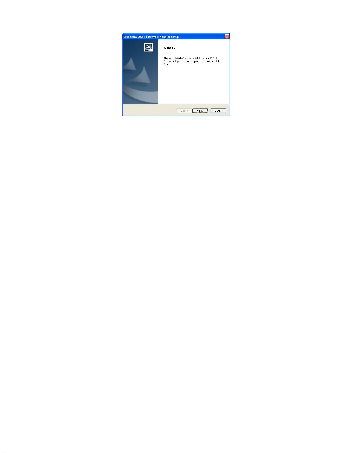
c. Choose Broadcom configuration Tool
and click next to go on
Page 3
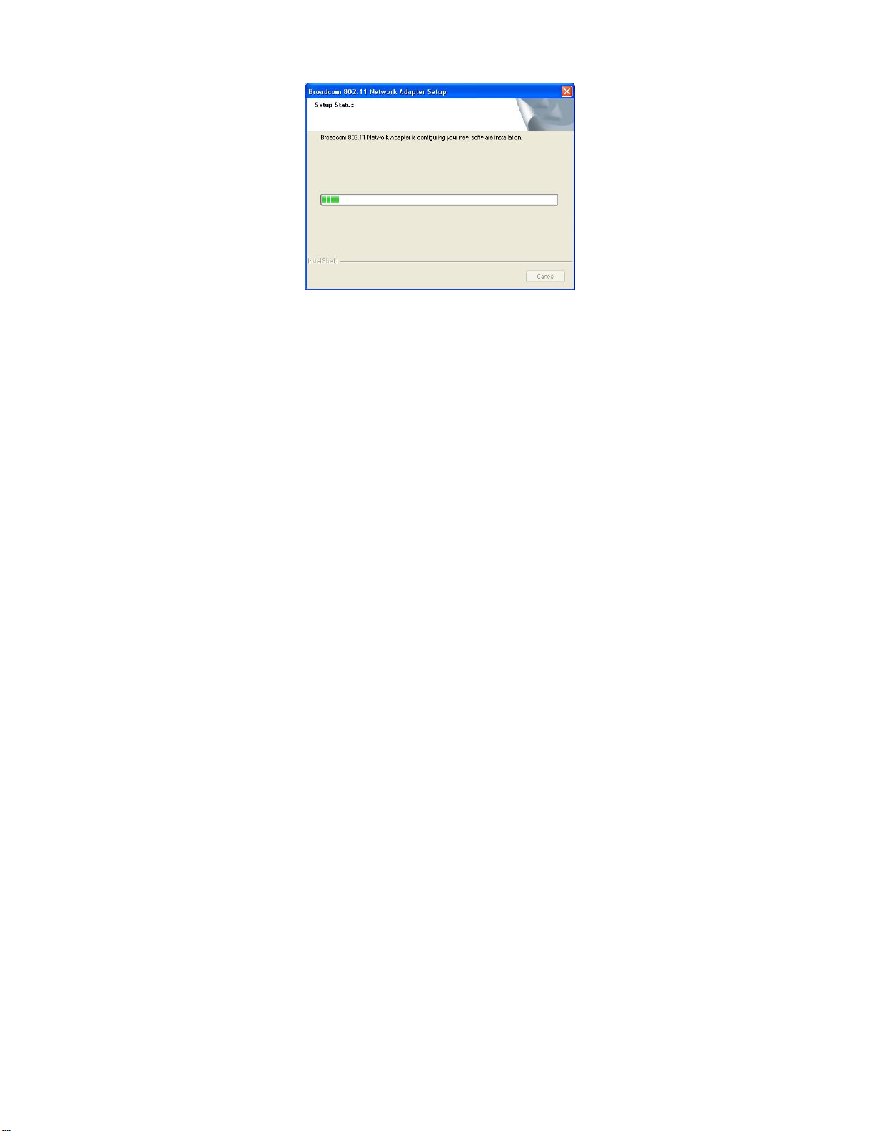
d. Choose optimize for wifi mode and
click next to go on
Page 4
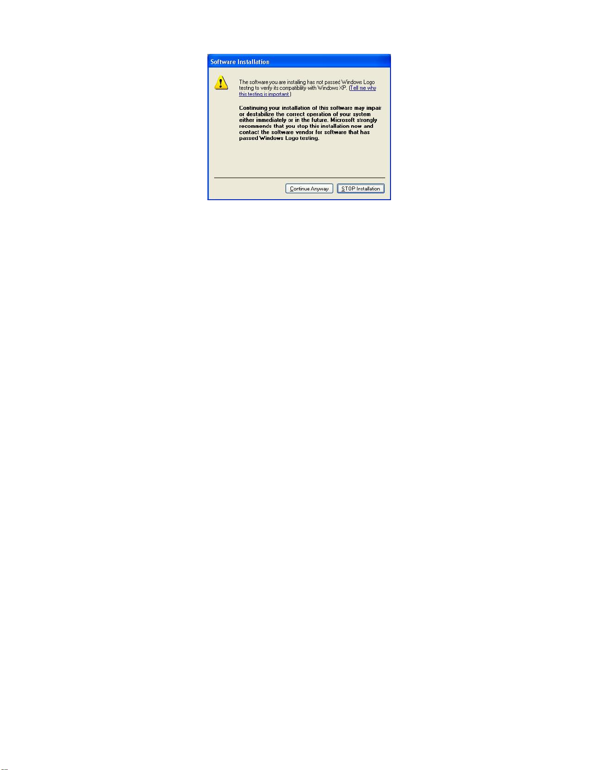
e. Choose Click Install to begin the
installation and click Install to go on
Page 5
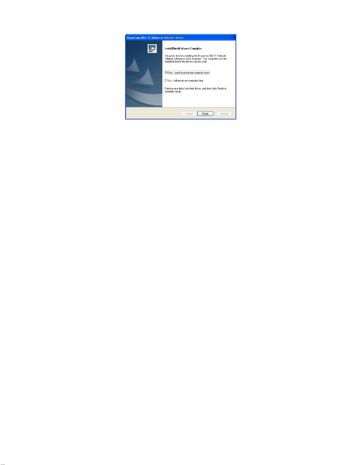
f. Click Finish to end the setup
2. Plug in your usb wireless LAN adapter,it
will be recognized and auto installed..Just
Page 6
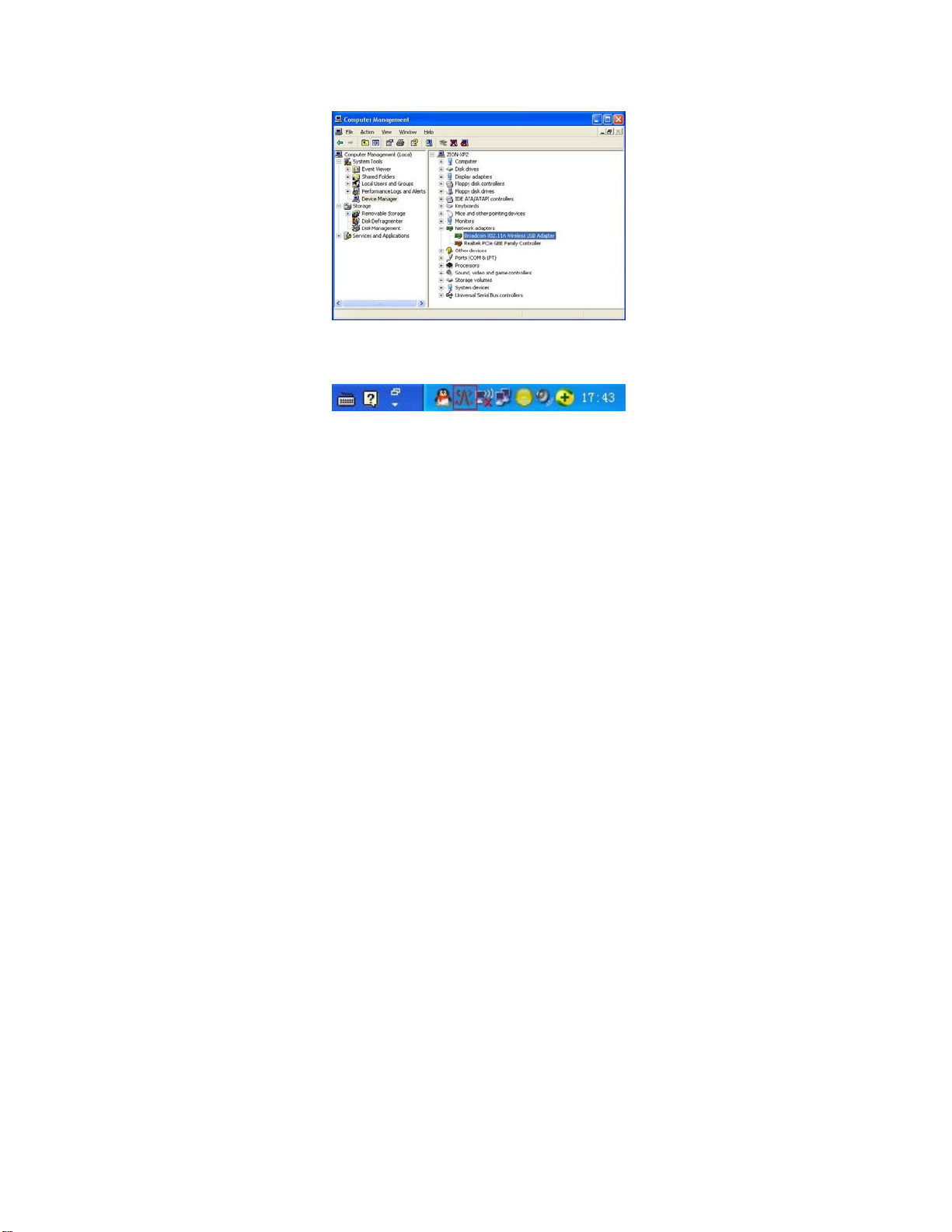
confirmed it like below:
3. Make infrastructure connection
Double click the icon in red circle
Page 7
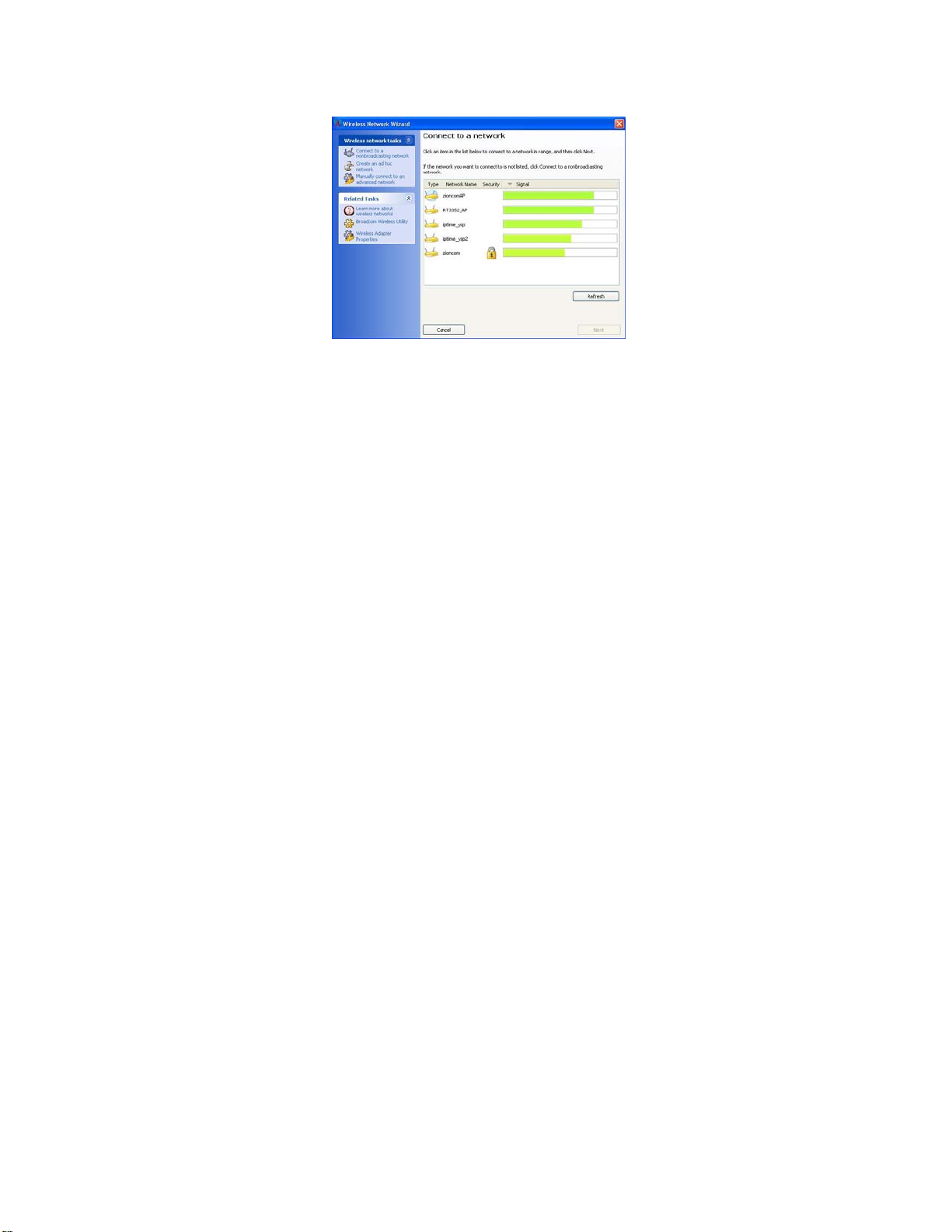
You will se e:
You can click the button Rescan to find which AP
is in range,the will show on the window,choice
one you want to connect,and click the button
Page 8

connect.
An infrastructure connection is accomplished.
Note,please choose correct channel setting up
to your law,for example,ch13 is permitted in
your country,and you set your router at
ch13,while you choose ch1-ch11(default
setting),you will never find the AP,and you will
have to choose ch1-ch13 seting in Advanced
page as below.
Page 9

4. Some help information in Broacom
Wireless utility
● How to find out your ip address:
Page 10

5.Mske Ad-hoc mode connection
●Mske an Ad-hoc SSID
Page 11

● A
Page 12

● B
Page 13

Page 14

● C
5.2 Setup static IP address for the
AD-Hoc link
Page 15

●A At its property page,double click item
Internet Protocol(TCP/IP)
● B You will get
Page 16

● C Fill the IP address blank,example as
below:
Page 17

● D Click ok to finish the setup
Page 18

5.3 Ad-Hoc setup for one point accomplished
5.4 Setup another Ad-hoc point as step A、B、
C、D.
5.5 Ad-hoc mode link accomplished.And you
can visit each other.
Page 19

Note:To make an Ad-Hoc mode link.Do
remember to choice the same channel.Its static
IP address should be in the same netsub,and
the SSID should be the same too.
Page 20

Installation Guide:
1. This RF Module can be mounted to the end product by
USB port.
2. Please follow the USB pin assignment and dimension of
RF module for the end product design.
3. Thick and short PCB trace for VDD and GND should be
made.
4. Decoupling capacitor is recommended to place next to
the VDD pin.
5. Make sure there are no metallic objects placed on to or
below the RF module after it is installed.
6. Only trace antennas are allowed to be used when the RF
module installed.
Page 21

7. Make sure that the specified supply voltage is not
exceeded.
8. Make sure that the power supply is clean (low noise and
ripple).
9. Unused connection and test point on the transceiver
module should be disconnected.
10. The RF module is self-sufficient to function without the
need of external components.
Important notes:
Please note that the module is only approved for use when
installed in devices produced by a specific manufacturer for
professional installation.
Page 22

Important notes to third party user for transceiver
module:
The transceiver Module complies with Part15 of the FCC
rules and regulations. Compliance with the labeling
requirements, FCC notices and antenna usage guidelines is
required. To fulfill FCC Certification, the third party user
must comply with the following regulations:
1. The third party user must ensure that the text on the
external label provided with this device is placed on the
outside of the final product. Contains FCC ID:
A2HWL0217. The enclosed device complies with Part
15 of the FCC Rules. Operation is subject to the following
two conditions: (1) this device may not cause harmful
interference, and (2) this device must accept any
Page 23

interference received, including interference that may
cause undesired operation.
2. The transceiver Module may only be used with the
onboard PCB trace antenna that have been tested and
approved for use with this module.
3. The transceiver Module have been certified by the FCC
for use with other products without any further
certification. Modifications not approved by ALCO
Electronics Ltd. could void the user’s authority to operate
the equipment.
4. Third party users must test final product to comply with
unintentional radiators before declaring compliance of their
final product to Part 15 of the FCC Rules.
Page 24

FCC Statement:
This device complies with Part 15 of the FCC Rules.
Operation is subject to the following two conditions: (1)
this device may not cause harmful interference, and (2)
this device must accept any interference received,
including interference that may cause undesired operation.
Warning: Changes or modifications to this unit not
expressly approved by the party responsible for
compliance (MLB International Inc., P.O. Box 1535,
Buffalo, NY 14226, Tel: 516-236-4556) could void the
user's authority to operate the equipment.
Page 25

NOTE: This equipment has been tested and found to
comply with the limits for a Class B digital device,
pursuant to Part 15 of the FCC Rules. These limits are
designed to provide reasonable protection against harmful
interference in a residential installation. This equipment
generates, uses and can radiate radio frequency energy and,
if not installed and used in accordance with the
instructions, may cause harmful interference to radio
communications.
However, there is no guarantee that interference will not
occur in a particular installation. If this equipment does
cause harmful interference to radio or television reception,
which can be determined by turning the equipment off and
Page 26

on, the user is encouraged to try to correct the interference
by one or more of the following measures:
1. Reorient or relocate the receiving antenna.
2. Increase the separation between the equipment and
receiver.
3. Connect the equipment into an outlet on a circuit
different from that to which the receiver is needed.
4. Consult the dealer or an experienced radio/TV technician
for help.
 Loading...