

Alcatel-Lucent Enterprise OS99-GNI-48, OS99-CMM, OS99-XNI-U48, OS99-GNI-P48, OS9907-CFM Hardware User's Manual
...
Alcatel-Lucent Enterprise
OmniSwitch 9900 Series
Hardware Users Guide
Part No. 060409-10, Rev C
July 2017

This user guide documents OmniSwitch 9900 Series hardware, including chassis and associated components.
The specifications described in this guide are subject to change without notice.
enterprise.alcatel-lucent.com
Alcatel-Lucent and the Alcatel-Lucent Enterprise logo are trademarks of Alcatel-Lucent. To view other
trademarks used by affiliated companies of ALE Holding, visit: enterprise.alcatel-lucent.com/trademarks.
All other trademarks are the property of their respective owners. The information presented is subject to
change without notice. Neither ALE Holding nor any of its affiliates assumes any responsibility for
inaccuracies contained herein. (2017)

Contents
About This Guide 1
Related Documentation .............................................................................................1
Product Release Notes .......................................................................................1
Customer Support....................................................................................................1
Chassis and Power 2
OmniSwitch 9900 Series.............................................................................................3
Chassis Front Panel ..........................................................................................5
Chassis Rear Panel............................................................................................6
Chassis Rear Panel (Fan Trays Removed) .................................................................7
Chassis Management.................................................................................................8
OS99-CMM......................................................................................................8
Switch Fabric .........................................................................................................11
OS9907-CFM....................................................................................................11
NI Modules............................................... ....... ........ ....... ....... ........ ....... ....... ........ ...12
OS99-XNI-48....................................................................................................12
OS99-XNI-U48..................................................................................................12
OS99-GNI-48 ...................................................................................................12
OS99-GNI-P48..................................................................................................13
OS99-GNI-U48..................................................................................................13
NI Module LEDs .......................................................................................................14
Fan Trays ..............................................................................................................15
Power Supplies .......................................................................................................16
OS99-PS-A (AC Power Supply)...............................................................................16
OS99-PS-D (DC Power Supply)...............................................................................16
DC Power Supply Connection.......................................................................................18
Connecting a DC Cable Harness to the Chassis Power Supply..........................................18
Getting Started and Installation 19
Getting Started.......................................................................................................20
Preparing for the Installation................................ ....... ....... ........ ....... ....... ........ ...20
Items Included.................................................................................................21
Airflow Considerations .......................................................................................22
Mounting the Chassis ................................................................................................23
Standalone (Non-Rack Mounted) Installation.............................................................23
Rack Mounting.................................................................................................23
Installing Chassis Components......................................................................................24

Installing Fabric Modules ....................................................................................24
Installing Fan Trays...........................................................................................26
Installing Modules.............................................................................................29
Installing a Power Supply....................................................................................30
Connections and Cabling.....................................................................................32
Booting the Switch...................................................................................................33
Component LEDs ..............................................................................................33
The First Login Session.......................................................................................34
Unlocking Session Types .....................................................................................35
Changing the Login Password ...............................................................................36
Setting the System Time Zone..............................................................................36
Setting the Date and Time ..................................................................................36
Setting Optional Parameters................................................................................37
Viewing Your Changes........................................................................................37
Saving Your Changes..........................................................................................37
Working with Chassis Power Budget .......................................................................38
Power Over Ethernet (PoE) 39
Managing Power over Ethernet (PoE) .............................................................................40
Viewing Power Supply Status................................................................................41
Viewing PoE Status ...........................................................................................41
PoE Class Detection ..........................................................................................42
PoE Operational Status.......................................................................................43
Setting Port Priority Levels..................................................................................45
Understanding Priority Disconnect.........................................................................46
Removing Chassis Components 48
Removing Chassis Components.....................................................................................48
Removing a Power Supply ...................................................................................48
Removing Fan Trays ..........................................................................................50
Removing Fabric Modules....................................................................................51
Removing Modules ...................................................................................................53
Hot Swapping .........................................................................................................54
General Guidelines ...........................................................................................54
Hot Swapping Power Supplies...............................................................................54
Hot Swapping CFMs...........................................................................................54
Hot Swapping NIs..............................................................................................54
Hot Swapping Compatibility.................................................................................54
Regulatory Compliance and Safety Information 55
Compliance and Certifications .....................................................................................56
EMI/EMC - Commercial.......................................................................................56
Safety Agency Certifications................................................................................56
Translated Safety Warnings ............................................................... ....... ...........60
Instrucciones de seguridad en español ....................................................................64

About This Guide
Related Documentation
The following related documents can found at enterprise.alcatel-lucent.com/userguides:
• OmniSwitch CLI Reference Guide
• OmniSwitch AOS Switch Management Guide
• OmniSwitch AOS Network Configuration Guide
• OmniSwitch AOS Advanced Routing Configuration Guide
• OmniSwitch AOS Data Center Guide
• OmniSwitch Transceivers Guide
Product Release Notes
Release Notes can be downloaded from the Customer Support website (account login required).
Customer Support
Web: support.esd.alcatel-lucent.com
Email: ebg_global_supportcenter@al-enterprise.com
1

1 Chassis and Power
2
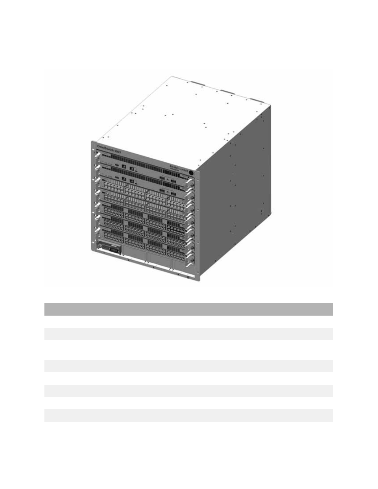
OmniSwitch 9900 Series
The Alcatel-Lucent Enterprise OmniSwitch 9907 11 RU modular LAN chassis.
OS9907 Chassis Specifications
Slots 7
Chassis Management Module (CMM) Slots 2
Chassis Fabric Module (CFM) Slots 4 (Slots CFM 3 and CFM 4 are currently inactive and are
Network Interface (NI) Slots 5
Fan Trays 3
Power Supplies 4
Rack Unit Dimensions 11 RU
Dimensions (HxWxD) 49.02 x 44.2 x 58.42 cm (19.3 x 17.4 x 23 in)
Weight (RCB) 32.83 kg (72.24 lb)
reserved for future use.)
3

OS9907 Chassis Specifications
Operating Temperature 0°C to 45°C (32°F to 113°F)
Storage Temperature 10°C to 70°C (14°F to 158°F)
Operating and Storage Humidity 10% to 90% (non-condensing)
Altitude 4000m/13,000 feet
4
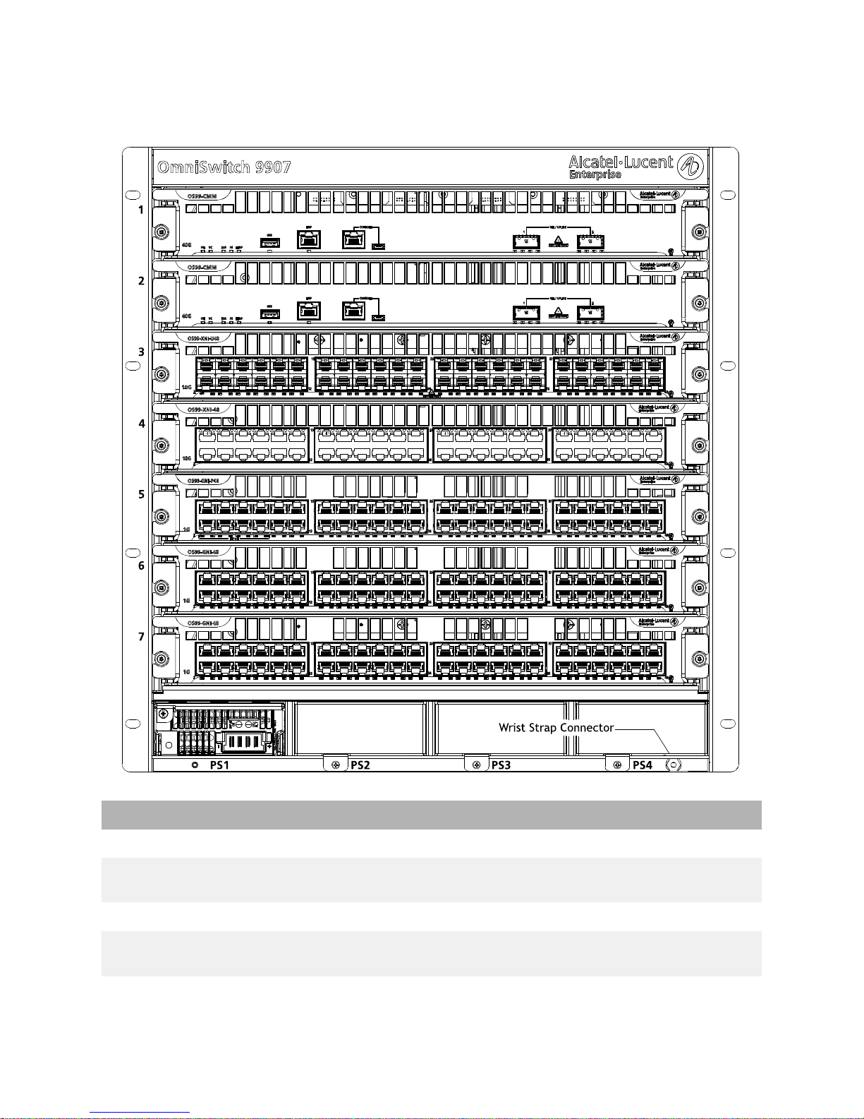
Chassis Front Panel
OS9907 Front Panel Components
Slot 1 Supports Chassis Management Module (CMM) only
Slot 2 Supports a CMM (for 1+1 CMM redundancy) or NI module
Slots 3 through 7 Support NI modules only
Slots PS1 through PS4 Support up to four load-sharing chassis power supplies,
Wrist Strap Grounding Connector Location shown in diagram above
(to maximize port count)
offering N+1 redundancy
5
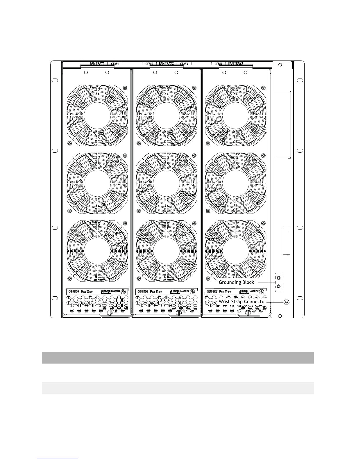
Chassis Rear Panel
Fan tray slot numbers are printed along the top-rear of the chassis.
OS9907 Rear Panel Components
Fan Tray Slots 1 through 3 Support three fan trays, with three fans per tray for N+1
Grounding Block Location shown in diagram above
Wrist Strap Grounding Connector Location shown in diagram above
fan redundancy
6
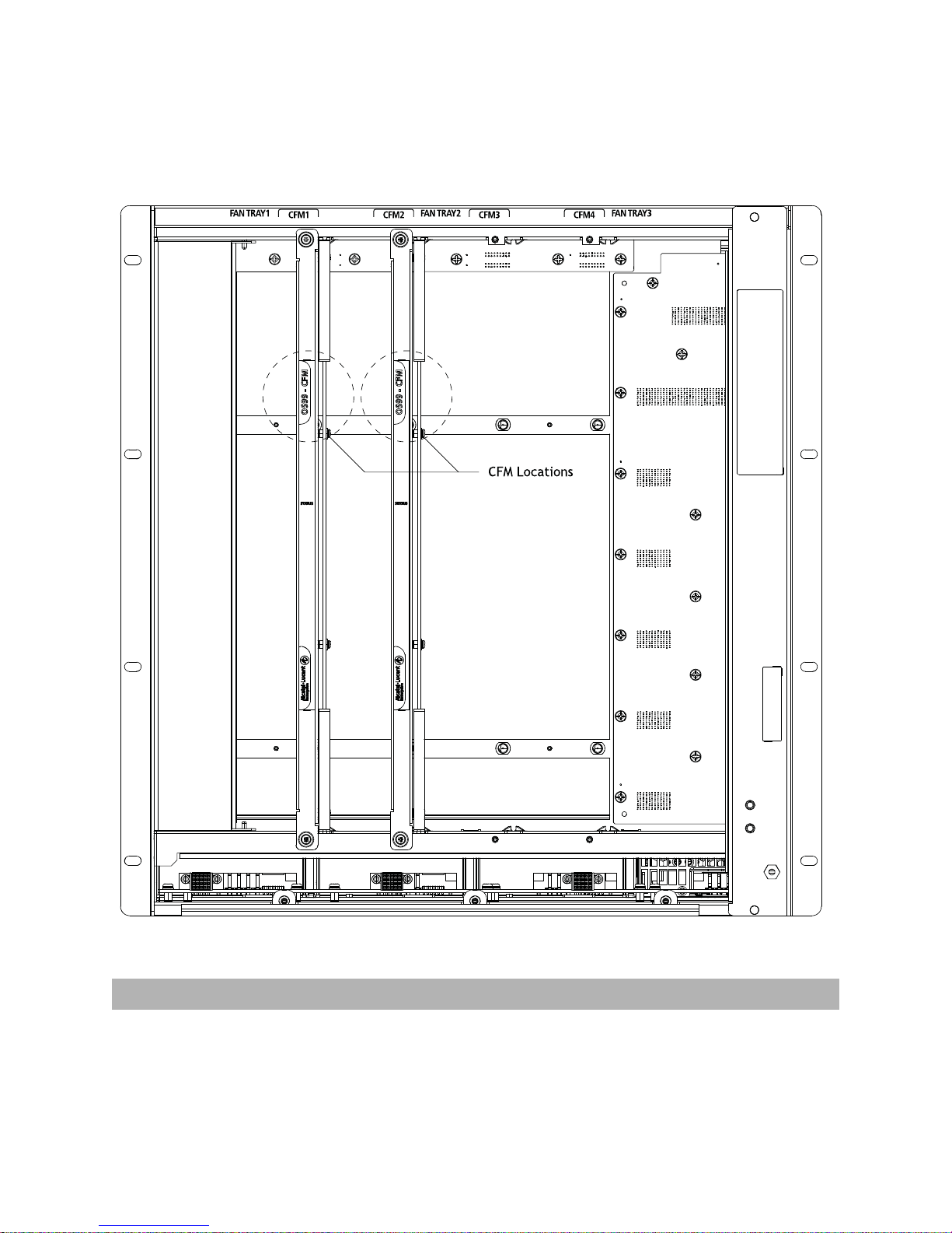
Chassis Rear Panel (Fan Trays Removed)
CFMs are located behind the chassis fan trays. To access a CFM, remove the fan tray in front of the
module. See “Removing Fan Trays” on page 50 for more information.
CFM slot numbers are printed along the top-rear of the chassis.
OS9907 CFM Location
Slots CFM1 through CFM4 For CFM module use only. Slots CFM1 and CFM2 are
currently supported; slots CFM 3 and CFM 4 are inactive
and reserved for future use
7
Chassis Management
92 1
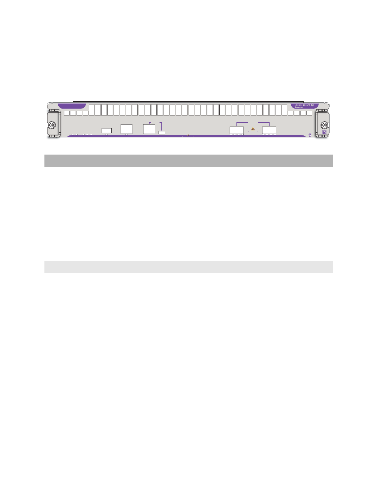
OS99-CMM
The CMM manages system functions in the chassis. This includes controlling and monitoring NIs, fabric
modules (CFMs) and power distribution. The CMM also provides two (2) 40G QSFP+ uplink ports.
OS99-CMM
40G
FAB PS
VC
PRI
USB
TEMP
EMP
CONSOLE
CLASS 1 LASER PRODUCT
VFL / UPLINK
12
ABC
CLASS 1 LASER PRODUCT
D
D
B
C
A
090992-10 C
CMM Specifications
Port Types (pictured from left to right) • USB Type A: For storage devices that can download
code or save configuration information, such as flashbased pen drives or external hard drives
• EMP (RJ45): 10/100/1000 Base-T with autonegotiation for out-of-band management (e.g.,
Telnet connection, diagnostics, downloading
software, etc.)
• Console (RJ45): For console or modem
• Console (Micro-USB*): For console or modem
• QSFP+ (Qty 2): 40G QSFP+ uplink ports
Power Consumption 64W
Number of Slots 2 (Slot positions 1 and/or 2. The slot 2 position may be
used for an NI module in lieu of a secondary CMM. Note
that, when an NI is installed in slot 2, CMM redundancy
is not provided.)
*Note. A driver is required for Micro-USB port operation. For information
on downloading the driver, refer to the OmniSwitch AOS Switch
Management Guide.
8

LEDs
Backlit Status LED Located at the module product name at the upper-left corner of
the front panel
• Solid Blue: HW OK
• Blinking Blue HW Bootup or HW Failure
Speed LED (40G) • Solid Green: HW OK
• Solid Red: HW Failure
• Blinking Green: SW OK (Heartbeat); the module is booted
and operating normally
• Solid Yellow: SW System Failure
PRI • Solid Green: CMM has Primary status
• Blinking Green: CMM has Secondary status
• Solid Yellow: CMM not operating
• Blinking Yellow: Software upgrade in progress
VC Virtual Chassis (reserved for future use)
FAB • Solid Green: Fabric modules (CFMs) operating normally
• Solid Yellow: Fabric module (CFM) error
PS • Solid Green: Power supplies are operating normally
• Solid Yellow: Power supply error
TEMP • Solid Green: System temperature is normal
• Solid Yellow: System temperature error (e.g., overtemp)
• Blinking Yellow: Fan error
USB • Solid Green: USB device/drive connected
• Blinking Green:USB device/drive transferring data
EMP • Solid Green: USB Port Link
• Blinking Green: USB Port Link and Activity
VFL/UPLINK Refer to “QSFP+ LED Display” below.
QSFP+
LED Display
Admin
Status
Link Status Transceiver Traffic VFL Port Speed
1G/10G (SFP+)
40G/4X10G
(QSFP+)
Off Down Down N/A N/A N/A N/A
Off Up Down No N/A N/A N/A
Solid Green Up Up Yes No No 10G (SFP+)
40G (QSFP+)
9

QSFP+
LED Display
Admin
Status
Link Status Transceiver Traffic VFL Port Speed
1G/10G (SFP+)
40G/4X10G
(QSFP+)
Solid Yellow Up Up Yes No No 1G (SFP+)
4X10G (QSFP+)
Solid BlueUpUpYesNoYesN/A
Blinking
Green
Blinking
Yellow
Blinking
Up Up Yes Yes No 10G (SFP+)
40G (QSFP+)
Up Up Yes Yes No 1G (SFP+)
4X10G (QSFP+)
Up Up Yes Yes Yes N/A
Blue
White N/A N/A Yes N/A N/A 4X10G
Note. Because OS99-CMMs provide splitter cable support on QSFP+ ports, port
LED behavior for these switches differs from other OS9900 modules. T o manually
configure network LED colors, refer to the interfaces beacon command in the
OmniSwitch AOS Release 8 CLI Reference Guide.
10
Switch Fabric
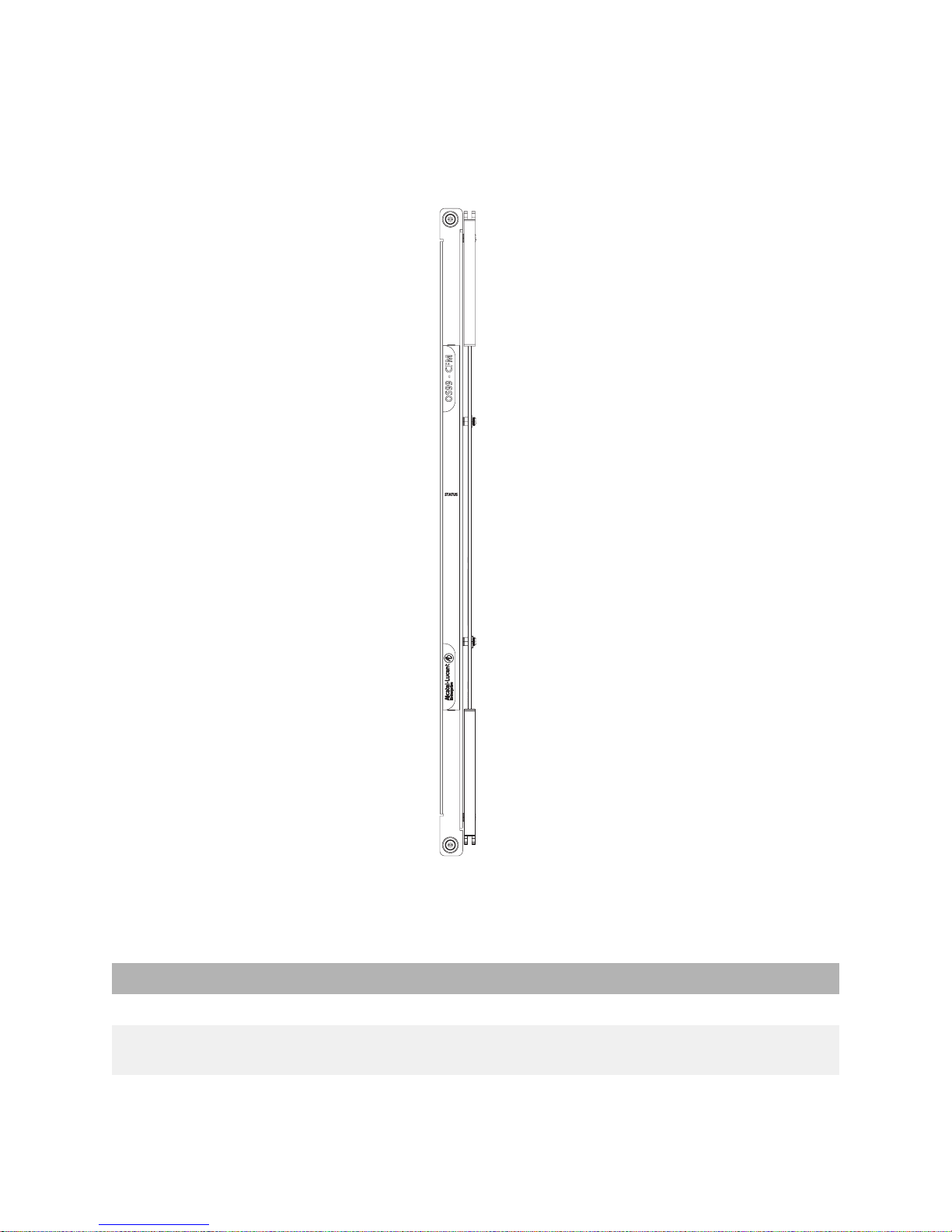
OS9907-CFM
Each OS9907-CFM installed provides 1280Gbps of switch fabric bandwidth to chassis management and
the Network Interface (NI) modules. The chassis provides four (4) OS9907-CFM slots. The modules
connect to the chassis mid-plane and are located just behind the system fan trays.
CFM Specifications
Switch Fabric Bandwidth 1280Gbps
Number of Slots 4 (Slots CFM 3 and CFM 4 are currently inactive
Power Consumption 119W
and are reserved for future use.)
11
NI Modules
10G
2
090990-10 C
24
25
13
12
37
36
48
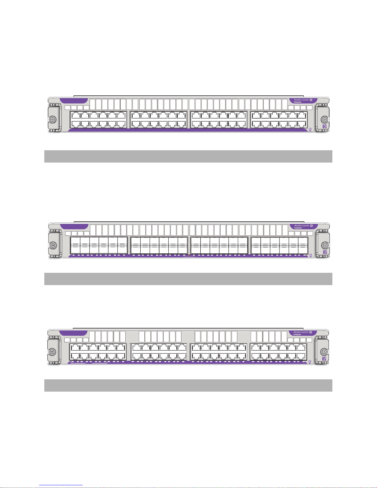
OS99-XNI-48
90 1CC
0 C0 0
10G
2
1
23
4
7
5
6
8
9 10
11
12
13
14 15
16 17 18
19
2021232224
25
26
27 28 29
333031
32
34 35
36 3738394041
42
43 44
45
46
47 48
090989-10 C
24
25
13
12
37
36
48
OS99-XNI-U48
89 1
0 CC0 C
0 C
0 C
0 C0 0 0 0
0
CLASS 1 LASER PRODUCT
1G
2
1
23
4
7
5
6
8
9 10
11
12
13
14 15
16 17 18
19
2021232224
25
26
27 28 29
333031
32
34 35
36 3738394041
42
43 44
45
46
47 48
090985-10 C
24
25
13
12
37
36
48
OS99-GNI-48
HPoE
85 1
0 CC0 C
0 C
0 C
0 C0 0 0 0
0
OS99-XNI-48
Port Type Number of Ports Power Consumption
1/10 GigE Base-T 48 402W
OS99-XNI-U48
Port Type Number of Ports Power Consumption
1/10 GigE SFP+ 48 305W
OS99-GNI-48
Port Type Number of Ports Power Consumption
10/100/1000 Base-T 48 56W
12
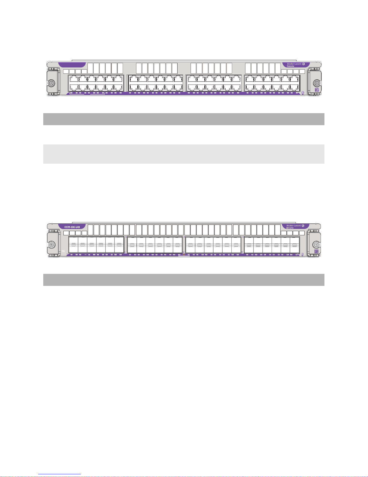
OS99-GNI-P48
86 1
0 CC0 C
0 C
0 C
0 C0 0 0 0
0
CLASS 1 LASER PRODUCT
CLASS 1 LASER PRODUCT
OS99-GNI-P48
13
25
37
1G
2
5
1
4
7
8
6
23
HPoE
9 10
12
11
13
12
14 15
16 17 18
19
2021232224
24
26
27 28 29
25
333031
32
36
34 35
36 3738394041
43 44
45
47 48
46
42
48
Port Type Number of Ports Power Consumption
10/100/1000Base-T PoE 48 54W, excluding any attached
Powered Devices (PDs)
HPoE Ports Ports 1 through 8 support HPoE (75W). These ports are labeled
“HPoE” on the chassis front panel.
OS99-GNI-U48
090986-10 C
Port Type Number of Ports Power Consumption
1 GigE SFP 48 70W
13

NI Module LEDs
NI Module LEDs
Backlight Status LED Located at the module product name at the upper-left corner of
the front panel
• Solid Blue: HW OK
• Blinking Blue HW Bootup or HW Failure
Speed LED Located at the left side of the front panel and indicates the
maximum port speed for the module (e.g., 10G)
• Solid Green: HW OK
• Solid Red: HW Failure
• Blinking Green: SW OK (Heartbeat); the module is booted
and operating normally
• Solid Yellow: SW System Failure
Power Save LED Reserved for future use
Port Status LEDs • Solid Green: Non-PoE Port Link
• Blinking Green: Non-PoE Port Link and Activity
• Solid Yellow: PoE Port Link (PoE modules only)
• Blinking Yellow: PoE Port Link and Activity (PoE modules only)
14
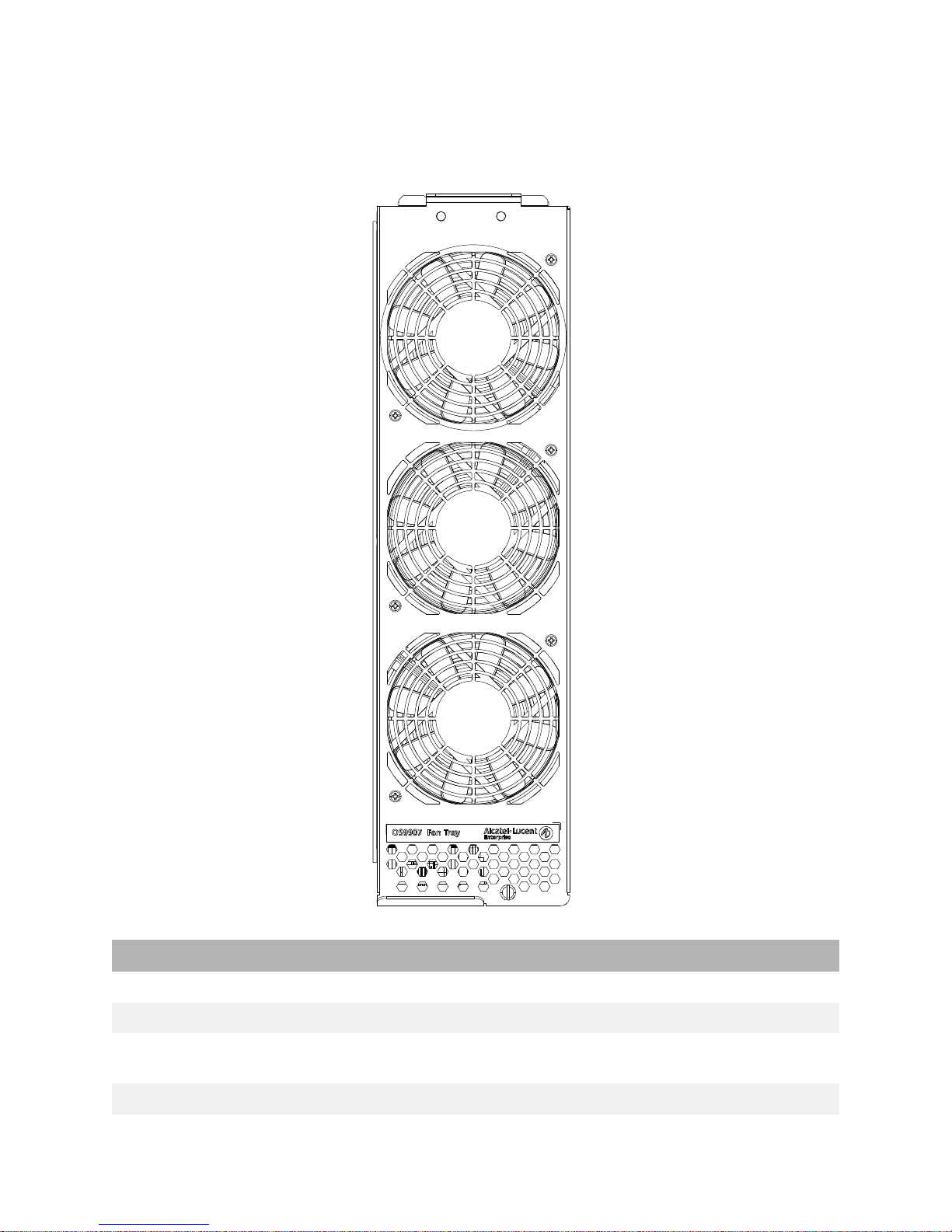
Fan Trays
The chassis provides three (3) fan tray slots for chassis air and temperature control.
Fan Tray Specifications
Number of Fan Tray Slots 3 (with three fans per tray for N+1 fan redundancy)
Airflow Direction Front-to-back only
Hot Swapping Supported (Three fan trays are required at all times; removal of a
Power Consumption 112W
fan tray is allowed for fan tray or CFM field replacement only.)
15
Power Supplies
Note: Mixing of AC and DC power supplies is not supported. Mixing of Hi
(240VAC) and Low (110VAC) input is not supported.
OS99-PS-A (AC Power Supply)
OS99-PS-A Specifications
Input Voltage/Current 100 VAC (13.8A) to 240V AC (16.5 A)
Max Output Power/Current 1200 W/21.4 A
3000 W/53.5 A
Dimensions 1.63 in x 4 in x 17.2 in
Weight 4.8 lb (2.18 kg)
Hot Swapping Supported
Provides Power for System and PoE
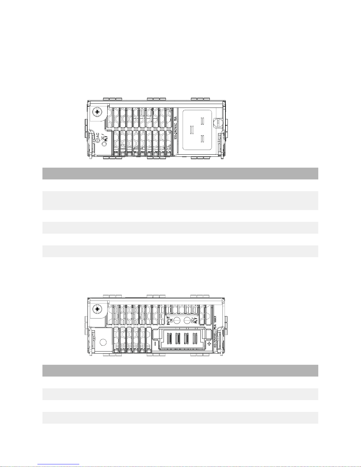
OS99-PS-D (DC Power Supply)
OS99-PS-D Specifications
Input Voltage/Current -40 VDC to -72 VDC / 75 ADC (At input voltages > 40 VDC)
Max Output Power 2500 W (44 - 58 VDC)
Max Output Current 44.6 A @ 56 VDC
Dimensions 1.63 in x 4 in x 17.2 in
16

OS99-PS-D Specifications
Weight 4.6 lb (2.1 kg)
Hot Swapping Supported
Provides Power for System and PoE
17

DC Power Supply Connection
Connecting a DC Cable Harness to the Chassis Power Supply
When plugging in the cable, insert the connector end of the cable harness into the power supply
connector until it clicks firmly into place. This is an indication that the connector is secure and properly
seated.
Connecting a DC Cable Harness to the DC Power Source
The other end of the cable harness is bare. Users must assemble and connect this end to the DC power
source or to a cable coming from the power source. In addition to following the important guidelines
listed below, be sure to consult manufacturer specifications for the DC power source before starting.
• Connect the power supply to a reliably grounded 48V or 60V SELV source.
• The branch circuit overcurrent protection must be rated 75A.
• Use two 10 AWG copper conductors.
• A readily accessible disconnect device that is suitably approved and rated shall be incorporated in
the field wiring.
• The above product(s) shall be installed in a restricted access location.
• The power supply shall used with an 4P PWRBLADE CONNECTOR, FCI model 10080598-2ED0006LF.
CAUTION: Installation of a DC cable that is more than 3 meters in length is
subject to LOCAL CODES and AUTHORITIES. Please contact your electrician and
the Local AHJ (Authority Having Jurisdiction) to follow the Electrical Codes
before use of proper installation methods.
18

2 Getting Started and
Installation
19

Getting Started
Preparing for the Installation
• Alcatel-Lucent Enterprise products must be installed by a professional installer. It is the
responsibility of the installer to comply with product specifications and all applicable local and
national codes.
• When preparing for installation, unpack the product as close as possible to the location where it will
be installed.
• Do not attempt to move or install a fully loaded chassis. To avoid injury and/or damage to the
product, two or more people are required when lifting.
Elevated Operating Ambient Temperature
If installed in a closed or multi-rack assembly, the operating ambient temperature of the rack
environment may be greater than the room’s ambient temperature. Therefore, consideration should be
given to the maximum rated ambient temperature (Tmra).
Reduced Air Flow
Installation of the equipment should be such that the amount of air flow required for safe operation of
the equipment is not compromised. Refer to “Airflow Considerations” on page 22 for more information.
Mechanical Loading
Mounting of the equipment in the rack should be such that a hazardous condition is not achieved due to
uneven loading.
Circuit Overloading
Consideration should be given to the connection of the equipment to the supply circuit and the effect
that overloading of circuits could have on overcurrent protection and supply wiring. Appropriate
consideration of equipment nameplate ratings should be used when addressing this concern.
Reliable Earthing
Reliable earthing of rack-mounted equipment should be maintained. P articular attention should be given
to supply connections other than direct connections to the branch (e.g., use of power strips).
OmniSwitch 9900 Series switches have the following general electrical requirements:
• Each switch requires one grounded electrical outlet for each power supply installed in the chassis.
• OmniSwitch 9900 Series switches offer both AC and DC power supply support.
• For switches using AC power connections, each supplied AC power cord is 2 meters (approx. 6.5
feet). Do not use extension cords.
Redundant AC Power. It is recommended that each AC outlet resides on a
separate circuit. With redundant AC power, if a single circuit fails, the switch’s
remaining power supplies (on separate circuits) can remain operational.
For switches using DC power, refer to “DC Power Supply Connection” on page 18 fo r mor e info rm ati on.
20

Electrical Surge Warning
In order to help protect equipment against electrical surges please take note of the following
recommendations and guidelines:
1. Earth grounding of all devices is fundamental to ensure long term reliability.
• All electrical equipment must be installed by a qualified, licensed electrician.
• Every power supply that is connected to building power should be earth grounded.
• Earth grounding for the power cable, should be verified to be 0.01 ohm or less.
• Each switch should be grounded to same earth ground as the power supply.
• Each powered device, such as an AP or camera, should be connected to earth ground.
• Each surge suppression device should be connected to earth ground.
2. Shielded cables (STP) offer some minimal level of additional protection over unshielded Ethernet
cables (UTP) but the use of a surge protector is still recommended.
• It is suggested to use STP Cat5e or better for 1Gbps Ethernet switches for any outdoor application
or applications where Ethernet cables come in close proximity to alternating current conductors.
• Always install cables according to manufacturer requirements.
3. For any connections where integrity of the cabling within a building ground is questionable (i.e
outdoor connections), copper Ethernet ports must be connected with an appropriate surge
protection device, inline, between the PSE and PD per the manufacturer’s recommendations for
connection and grounding.
4. Caution should be taken for any cable connected to any outdoor device, not only on the device
grounding, but to ensure that any outdoor device cables that could carry surge currents, do not pass
those surge currents to upstream Ethernet switches.
Caution - Category 5e, Category 6, and Category 6a cables can store large amounts of static
electricity due to the dielectric properties of their construction materials in addition, this build up
of electricity could lead to a Cable Discharge Event (CDE). A CDE can occur due to the differential in
charges on the cable and the equipment it’s being connected to. It is recommended that installers
momentarily ground all copper Ethernet cables (especially in new cable runs) to a suitable and safe
earth ground before connecting them to the port.
Items Included
Depending on your order the following items may be included:
• OmniSwitch Chassis with power supplies and modules
• Country specific power cord(s)
•Cover Panels
• Rack Mount Brackets
• Product Documentation and Training Cards
• DB9-RJ45 Connector
• Grounding Wrist Strap
21

Airflow Considerations
To ensure proper airflow, be sure that the switch is placed in a well-ventilated area and provide
minimum recommended clearance at the front, back and sides of the switch.
Never obstruct chassis or component air vents. Restricted airflow can cause the switch to overheat,
which can lead to system failure and damage to the product.
Note. Clearance is not required at the top and bottom of the chassis.
Blank Cover Panels
Blank cover panels are used to cover empty module slots and power supply bays. Because they regulate
airflow and help protect internal chassis components, blank cover pane ls should be installed over empty
module slots and power supply bays at all times.
Missing Blank Cover Panels Adversely Affect Chassis Airflow
22

Mounting the Chassis
Note. Due to weight and airflow requirements, OS9907 switches cannot be
wall mounted.
Standalone (Non-Rack Mounted) Installation
The chassis can be placed unmounted on a stable, flat surface as a standalone unit. Be sure that the
surface can accommodate the full, populated weight of all switches being installed. Approximate chassis
weights are provided in “OS9907 Chassis Specifications” on page 3.
For a standalone unit, use two or more people to move and position the unpopulated chassis upright on
the surface where it is to be installed. Be sure that adequate clearance has been provided for chassis
airflow and that you have placed the chassis within reach of all required AC outlets. For recommended
airflow allowances, refer to “Airflow Considerations” on page 22.
Note. The chassis must be placed “right side up.” Never attempt to operate a
switch while it is lying on its side or back.
Rack Mounting
General Rack Mounting Recommendations
• Install the switch in the rack using the rack manufacturer’s recommended attachment screws (not
provided). Always follow rack manufacturer’s specifications when installing.
• The OmniSwitch 9907 is an 11 RU high unit.
• Pre-marking the holes on the rack where the switch is to be installed can be helpful when installing
multiple switches in a rack.
• Use two additional people to help lift and position the chassis in the rack during installation.
• To keep the rack from becoming top heavy, install switches toward the bottom of the rack first.
Non-Standard Rack-Mounting Hardware
All OmniSwitch 10K switches are shipped with integral front rack mount flanges. These flanges
support standard 19” rack mount installations. For non-standard rack mount requirements, contact
Alcatel-Lucent Enterprise for information on optional hardware availability.
23

Installing Chassis Components
Installing Fabric Modules
To access OS9907-CFM slots, be sure the fan trays covering the slots have been removed. (For
information on removing fan trays, refer to “Removing Fan Trays” on page 50.)
1. To install a OS9907-CFM, orient the module so the top (component side) of the circuit board
faces left.
Insert the edges of the circuit board into the card guides at top and bottom (see inset) and partially
slide the module back toward the chassis mid-plane.
2. When the module reaches the mid-plane connectors, hold the top and bottom lock levers in the
open position and slide the module back until it stops.
24

3. Simultaneously press the top and bottom lock levers until the levers are in the vertical (locked)
position and the module is firmly seated in the chassis mid-plane.
4. Hand-tighten the captive screws at the top and bottom of the module.
5. Repeat these steps for additional CFMs (if applicable).
6. Install fan trays as needed. (For information on installing fan trays, refer to “Installing Fan Trays” on
page 26.)
25

Installing Fan Trays
1. Fan trays are secured by two tabs at the top of the unit and a captive thumb screw at the bottom of
the unit. Hold the fan tray by the top and bottom handles. Angle the tray away from the chassis at
the bottom, as shown, and insert the tabs at the top of the fan tray slot.
26

2. With the top tabs inserted, push the bottom of the tray into the slot until it is firmly seated.
27

3. Hand-tighten the thumb screw.
28

Installing Modules
1. To install a module, insert the edges of the circuit board into the grooves at the left and right sides
of the chassis.
2. Be sure the lock levers are in the open position and slide the module back until it meets the
backplane connectors.
3. Tighten the lock levers by pulling them inward (toward the center of the module’s front panel).
When the modules are fully closed (at a 90 degree angle with the front panel), the module will be
firmly seated.
When the module is fully seated, hand-tighten the thumb screws at the left and right sides of
the module.
29

Installing a Power Supply
Once the chassis components have been installed, install the power supplies.
Note. When connecting or disconnecting a power supply to/from a chassis, the
power supply must first be disconnected from the power source.
1. Remove blank cover panel from the power supply slot (if applicable) and store the cover panel for
future use.
2. With one hand, hold the front of the power supply. Place your other hand under the power supply to
support its weight. Insert the rear of the power supply into the slot. Be sure the handle is in the
down (open) position and slide the unit back until it meets the chassis backplane.
30

3. Press the handle up into the vertical (locked) position. The power supply should be fully seated in
the chassis backplane. Tighten the thumb screw to secure the power supply.
4. Plug in the power cord and then plug the power cord into an easily-accessible, properly grounded
outlet. (Do not use an extension cord.)
31

Connections and Cabling
Once the switch is properly installed, connect all network and management cables required network
applications.
Network Cable Installation Warning
Never install exposed network cables outdoors. Install network cables per manufacturer requirements.
For additional information on cabling for console, EMP, USB, Bluetooth and other connections, refer to
the OmniSwitch AOS Switch Management Guide.
Serial Connection to the Console Port
The console port provides a serial connection to the switch using either a Micro-USB or RJ45 connector
and is required when logging into the switch for the first time.
Serial Connection Default Settings
baud rate 9600
parity none none
data bits (word size) 8
stop bits 1
For information on modifying these settings, refer to the OmniSwitch AOS Switch Management Guide.
Ethernet Management Port (EMP) Cable Requirements
There are specific cable type requirements (i.e., straight-through or crossover) based on the device to
which the EMP is connecting. Refer to the information below:
Serial Connection Default Settings
EMP to a Switch Straight-through
EMP to a Computer or Workstation Crossover
For information on manually configuring Ethernet ports, refer to the OmniSwitch AOS Switch
Management Guide.
32

Booting the Switch
To boot the switch, plug all power supply cords into easily-accessible, properly grounded power outlets.
(Do not use extension cords.)
The switch will power on and boot automatically.
Note. If more than one power supply is installed, be sure to plug in each power
supply in rapid succession, (i.e., within a few seconds of each other). This
ensures that there will be adequate power for all components throughout the
boot process.
Component LEDs
During the boot process, component LEDs will flash and change color, indicating different stages of
the boot.
Following a successful boot, LEDs on the primary CMM should display as follows:
PRI Solid Green
PS Solid Green
FAB Solid Green
TEMP Solid Green
Note. Be sure the boot process is complete before checking LED status. If LEDs
indicate persist errors, contact Alcatel-Lucent Customer Support.
Once the switch has completely booted, connect to the console port and log in to the switch’ s Command
Line Interface (CLI) and configure basic information. Continue to “The First Login Session” on page 34.
33

The First Login Session
To complete the setup process, follow these steps during the first login session:
• Log in to the switch
• Set IP address information for the Ethernet Management Port (EMP)
• Unlock session types
• Change the login password
• Set the date and time
• Set optional system information
•Save changes
Important. Connect to the switch via the console port before initiating the first
login session.
Logging In to the Switch
At the login and password prompts, use the switch’s default settings:
Login admin
Password switch
The default welcome banner, which includes information such as the current software version and
system date, is displayed followed by the CLI command prompt:
Welcome to the Alcatel-Lucent Enterprise OS9900 8.3.1, June 03, 2016.
Copyright (c) 1994-2014 Alcatel-Lucent. All Rights Reserved.
Copyright (c) 2014-2016 Alcatel-Lucent Enterprise. All Rights Reserved.
OmniSwitch(tm) is a trademark of Alcatel-Lucent,
registered in the United States Patent and Trademark Office.
Note. A user account includes a login name, password, and user privileges.
Privileges determine whether the user has read or write access to the switch
and which commands the user is authorized to execute. For detailed
information on setting up and modifying user accounts, refer to the OmniSwitch
Switch Management Guide.
Setting IP Address Information for the EMP
The IP address may be set via the Ethernet Management Port (EMP). To connect to the switch through
the EMP Ethernet connection, use the default address below or change the port’s IP address.
Default EMP IP Address 192.168.1.1
Default EMP Mask 255.255.255.0
Note. Connect to the switch via the console port before attempting to change IP
address information.
34

To change the default IP and mask, use the ip interface command. For example:
-> ip interface emp address 168.22.2.120 mask 255.255.255.0
Verify the settings using the show ip interf ace command. See the OmniSwitch AOS Switch Management
Guide for additional information regarding EMP port addressing.
Note. The switch cannot be accessed through this port (i.e. TELNET, FTP, HTTP,
SSH or SNMP) until these remote session types have been unlocked. See
“Unlocking Session Types,” below, for more information.
Unlocking Session Types
When accessing the switch for the first time, users must use a direct console port connection. All other
session types (Telnet, FTP, WebView, and SNMP) are locked out until they are manually unlocked by
the user.
The CLI command used to unlock session types is aaa authentication.
Note. Unlocking session types grants access to non-local sessions (e.g., Telnet).
As a result, anyone with the correct user login and password will have remote
access to the switch.
For more information on switch security, refer to the OmniSwitch AOS Switch Management Guide.
Unlocking All Session Types
To unlock all session types, enter the following command syntax at the CLI prompt:
-> aaa authentication default local
Unlocking Specific Session Types
You can also unlock specific session types (console, telnet, ftp, http, snmp, ssh). For example, to unlock
Telnet sessio ns, enter the following command:
-> aaa authentication telnet local
Refer to the OmniSwitch CLI Reference Guide for complete aaa authentication command
syntax options.
35

Changing the Login Password
Change the login password for admin user sessions by following the steps below:
1. Be sure that you have logged into the switch as user type admin (see “Logging In to the Switch” on
page 34).
2. Type password at the prompt and press Enter.
3. Enter the new password at the prompt.
Note. Be sure to remember or securely record all new passwords; overriding
configured passwords on an OmniSwitch is restricted.
4. You will be prompted to re-enter the password. Enter the password a second time.
New password settings are automatically saved in real time to the local user database; the user is not
required to enter an additional command in order to save the password information. Also note that new
password information is retained following a reboot. All subsequent login sessions, including those
through the console port, will require the new password to access the switch.
For detailed information on managing login information, including user names and passwords, refer to
the OmniSwitch Switch Management Guide.
Setting the System Time Zone
The switch’ s default time zone is UTC. If you require a time zone that is specific to your region, or if you
need to enable Daylight Savings Time (DST) on the switch, you can configure these settings via the
system timezone and system daylight-savings-time commands.
For detailed information on configuring a time zone for the switch, refer to the OmniSwitch AOS Switch
Management Guide.
Setting the Date and Time
Set the current time for the switch by entering system time, followed by the current time in hh:mm:ss.
To set the current date for the switch, enter system date, followed by the current date in mm/dd/yyyy.
36

Setting Optional Parameters
Specifying an Administrative Contact
An administrative contact is the person or department in charge of the switch. If a contact is specified,
users can easily find the appropriate network administrator if they have questions or comments about
the switch.
To specify an administrative contact, use the system contact command.
Specifying a System Name
The system name is a simple, user-defined text description for the switch.
To specify a system name, use the system name command.
Specifying the Switch’s Location
It is recommended that you use a physical labeling system for locating and identifying your switch(es).
Examples include placing a sticker or placard with a unique identifier (e.g., the switch’s default IP
address) on each chassis.
However, if no labeling system has been implemented or if you need to determine a switch’s location
from a remote site, entering a system location can be very useful.
To specify a system location, use the system location command.
Viewing Your Changes
To view your current changes, enter show system at the CLI prompt.
Saving Your Changes
Once you have configured this basic switch information, save your changes by entering write memory at
the CLI command prompt.
37

Working with Chassis Power Budget
The power available to the chassis modules (CMM, CFM, and NI) is based on the user configuration and
system environment.
Adding additional components (e.g., NI modules, a redundant CMM, or powe red POE devices)—as well as
removing power supplies—affects the overall power budget for the switch.
As soon as a component is inserted and its connectors make contact with the chassis mid-plane,
additional power requirements take effect. If there is not adequate power, the incoming component
may not power on. Additional power errors may also occur, which can interrupt data flow on the switch.
So it is important to check the current chassis power before adding a module or removing a power supply
to verify that the current chassis power supports the change.
Use the show chassis command to determine available power budget (see Power Left number).
-> show chassis
Local Chassis ID 1 (Master)
Model Name: OS9900,
Description: Chassis,
Part Number: 903722-90,
Hardware Revision: B,
Serial Number: T4720029,
Manufacture Date: Feb 1 2016,
Admin Status: POWER ON,
Operational Status: UP,
Free Slots: 4,
Power Left: 2041,
Number Of Resets: 20,
MAC Address: 2c:fa:a2:13:e4:02
In this example, 2041 watts are available for incoming components and/or powered devices.
38

3 Power Over Ethernet (PoE)
39

Managing Power over Ethernet (PoE)
Important: Alcatel-Lucent Enterprise recommends that PoE-enabled switches
with attached IP telephones have operational power supply redundancy at all
times for 911 emergency requirements.
In addition, both the switch and the power supply should be plugged into an
Uninterruptible Power Source (UPS).
Power over Ethernet Specifications
Module(s) supporting PoE OS99-GNI-P48
IEEE Standards supported IEEE 802.3; 802.af; 802.3at
PoE Power Supported Ports 1 through 8 support HPoE (75 W)
Ports 9 - 48 support 802.3at PoE (30 W)
All PoE-enabled ports are IEEE 802.3af/at compliant.
Default PoE administrative
status
Default PoE operational status Disabled (PoE must be activated via the lanpower start
Power over Ethernet Settings Default Related Command
PoE operational status Disabled lanpower slot service
Total power available to a port 75000 milliwatts on ports 1
Total power available to an
entire slot
Power priority level for a port low lanpower priority
Capacitor detection method Disabled lanpower capacitor-detection
Priority disconnect status Enabled lanpower slot priority-disconnect
Enabled
command.)
lanpower power
through 8; 30000 milliwatts
on ports 9 through 48
1800W lanpower slot maxpower
40

Viewing Power Supply Status
To view the type and status for installed power supplies, use the show powersupply command:
-> show powersupply
Total Power Input PS
Slot PS Power Used Voltage Type Status Location
---------+---------+--------+---------+--------+--------+-----------
1 1200 487 122 AC UP Internal
2 0 0 0 AC UNPLUG Internal
3 0 0 0 AC UNPLUG Internal
Total 1200 487
Viewing PoE Status
To view current PoE status and settings, including the amount of PoE power available for incoming
powered devices, use the show lanpower slot command for the corresponding PoE module(s):
-> show lanpower slot 1/4
Port Maximum(mW) Actual Used(mW) Status Priority On/Off Class Type
----+-----------+---------------+-----------+---------+--------+-------+------
-- --
1 75000 0 Powered Off Low OFF .
2 75000 0 Powered Off Low OFF .
3 75000 0 Powered Off Low OFF .
4 75000 0 Powered Off Low OFF .
5 75000 0 Powered Off Low OFF .
6 75000 0 Powered Off Low OFF .
7 75000 0 Powered Off Low OFF .
8 75000 0 Powered Off Low OFF .
9 30000 0 Powered Off Low OFF .
10 30000 0 Powered Off Low OFF .
...
46 30000 0 Powered Off Low OFF .
47 30000 0 Powered Off Low OFF .
48 30000 0 Powered Off Low OFF .
ChassisId 1 Slot 4 Max Watts 0
0 Watts Actual Power Consumed
ChassisId 1 Slot 4 Max Watts Running 0
0 Watts Total Power Budget Used
2041 Watts Total Allocated PoE Power
2041 Watts Total Power Budget Available
2 Power Supplies Available
41

PoE Class Detecti on
Powered devices can be classified into different classes as shown in the table below. Class detection
allows for automatic maximum power adjustment based on the power class detected. This will prevent
the switch from delivering more than the maximum power allowed based on a device’s class.
During class detection, the switch will allocate the maximum amount of power allowed based on the
class detected. Once powered, if the device uses less than the maximum, the remaining power will be
made available for other devices.
Class Usage
Classification
0 Default 0-4 0.44-30.00 Unimplemented
1 Optional 9-12 0.44-3.84 Very Low Power
2 Optional 17-20 3.84-6.49 Low Power
3 Optional 26-30 6.49-12.95 Mid Power
4 Optional 36-44 12.95-30.00 High Power
Although class-detection is disabled by default, the PoE module still provides power to incoming PDs (if
available in the power budget). However, to strictly enforce class detection as specified in the 802.3at
standard, class detection must be enabled using the lanpower slot class-detection command.
Enabling class detection will reset all PoE ports.
Current (mA) Power Range
(Watts)
Class Description
42

PoE Operational Status
Enabling PoE
By default, PoE is administratively enabled in the switch’s system software. However, in order to
physically activate PoE, you must issue the lanpower slot service command on a slot-by-slot basis
before any connected devices will receive inline power.
To activate power to PoE-capable in a switch, enter the corresponding slot number only. For example:
-> lanpower slot 2/1 service start
If power to a particular port has been administratively disconnected, you can reactivate power to the
port using the lanpower port admin-state command. For example:
-> lanpower port 2/1/1-24 admin-state enable
Note. You cannot use the lanpower port admin-state command to initially
activate PoE on a port . This syntax is intended only to reactivate power to t hose
that have been disconnected via the lanpower slot service command. To
initially activate PoE, you must use the lanpower slot service command as
described above.
Disabling PoE
To disable PoE on a particular port, use the lanpower port admin-state command. For example:
-> lanpower port 1/1/12 admin-state disable
To disable PoE for all PoE-capable ports in a slot, use the lanpower slot service command. For example:
-> lanpower slot 1/1 service stop
Configuring the Total Power Available to a Port
By default, each port is authorized by the system software to use up to a maximum amount of milliwatts
to power any attached device.
This value can be increased or decreased based on the allowed ranges.
Increasing the total power available to an individual port may provide a more demanding powered
device with additional power required for operation. Decreasing the total power available to a port
helps to preserve inline power and assists in the overall management of the switch’s power budget.
To increase or decrease the total power available to an individual port, use the lanpower power
command.
Note. Since the power allowance is being set for an individual port, chassis/
slot/port values must be specified.
43

Configuring the Total Power Available to a Slot
Like the maximum port power allowance, the system software also provides a maxim um slot-wide powe r
allowance. By default, each slot is authorized by the system software to use a number of watts to power
all devices connected to its ports depending on which power supply is used.
As with the maximum port power allowance, the user can either increase or decrease this value based
on the allowed ranges.
Note. Decreasing the slot-wide power could cause lower priority ports to lose
power if the new value is less than the total PoE power currently being
consumed.
To increase or decrease the total power available to a slot, use the lanpower slot maxpower command.
Since you are setting the power allowance for an individual slot, you must specify a chassis/slot value i n
the command line. For example, the syntax
-> lanpower slot 3/1 maxpower 400
reduces the power allowance of chassis 3, slot 1 to 400 watts. This value is now the maximum amount of
power the slot can use to power all attached devices (until the value is modified by the user).
Note. Changing the maximum power available to a slot or port does not reserve
or immediately allocate that power. These settings are only used for configuring
a maximum amount of power that may be used, any unused power is still
available and remains a part of the overall PoE budget.
Setting Timers and Other User-Defined PoE Power Rules
The lanpower power-rule command allows user to set additional rules for PoE power (e.g., setting PoE
to turn on or off on specific dates or at specific times). Refer to the OmniSwitch AOS CLI Command
Reference Guide for more information.
44

Setting Port Priority Levels
As not all Powered Devices (PDs) connected to the switch have the same priority within a network
setting, the OmniSwitch allows the administrator to specify priority levels on a port-by-port basis.
Priority levels include low, high, and critical.
The default priority level for a port is low.
• Low. This default value is used for port(s) that have low-priority devices attached. In the event of a
power management issue, inline power to low-priority is interrupted first (i.e., before critical and
high priority).
• High. This value is used for port(s) that have important, but not mission-critical, devices attached.
If other ports in the chassis have been configured as critical, inline power to high-priority is given
second priority.
• Critical. This value is used for port(s) that have mission-critical devices attached, and therefore
require top (i.e., critical) priority. In the event of a power management issue, inline power to
critical is maintained as long as possible.
To change the priority level for a particular port, use the lanpower priority command. Since the switch
allows you to set priority levels on a port-by-port basis, be sure to specify chassis/slot/port information
in the command line. For example, the syntax
-> lanpower port 1/1/6 priority critical
changes the priority value of port 6 to the highest priority level of critical. Now that the default value
has been reconfigured, this port should be reserved for those PDs that are mission critical for network
operations.
Setting the Capacitor Detection Method
By default, the capacitor detection method is disabled. To enable it, use the lanpower capacitordetection command. For example:
-> lanpower slot 3/1 capacitor-detection enable
Note. The capacitive detection method should only be enabled to support
legacy IP phones. This feature is not compatible with IEEE specifications.
Please contact your Alcatel-Lucent sales engineer or Customer Support
representative to find out which Alcatel-Lucent IP phones models need
capacitive detection enabled.
45

Understanding Priority Disconnect
Priority disconnect is used by the system software in determining whether an incoming PD will be
granted or denied power when there are too few watts remaining in the PoE power budget for an
additional device. For example, if there are only 2 watts available in the current PoE power budget and
a user plugs a 3.5W powered device into a PoE port, the system software must determine whether the
device will be powered on.
Based on priority disconnect rules, in some cases one or more existing devices may be powered down in
order to accommodate the incoming device. In other cases, the incoming device will be denied power.
Priority disconnect rules involve the port priority status of an incoming device (i.e., low, high, and
critical), as well as the port’s physical port number. Understanding priority disconnect rules is especially
helpful in avoiding power budget deficits and the unintentional shutdown of mission-critical
devices when PDs are being added in tight power budget conditions.
Reminder. Priority disconnect applies only when there is inadequate power
remaining in the power budget for an incoming device.
For information on setting the priority disconnect status, refer to the section below. For information on
setting the port priority status (a separate function from priority disconnect), refer to “Setting Port
Priority Levels” on page 45.
Setting Priority Disconnect Status
By default, priority disconnect is enabled in the switch’s system software. For information on changing
the priority disconnect status, refer to the information below.
Disabling Priority Disconnect
When priority disconnect is disabled and there is inadequate power in the budget for an additional
device, power will be denied to any incoming PD, regardless of its port priority status (i.e., low, high,
and critical) or physical port number.
To disable priority disconnect, use the lanpower slot priority-disconnect command. For example:
-> lanpower slot 2/1 priority-disconnect disable
Enabling Priority Disconnect
To enable priority disconnect, use the lanpower slot priority-disconnect command. For example:
-> lanpower slot 2/1 priority-disconnect enable
46

Priority Disconnect is Enabled; Same Priority Level on All Devices
Reminder. Priority disconnect examples are applicable only when there is
inadequate power remaining to power an incoming device.
When a PD is being connected to a port with the same priority level as all other in the slot, the physical
port number is used to determine whether the incoming PD will be granted or denied power. Due to the
support of different PoE standards and PoE hardware on each platform the internal port priority is
different for each platform. The following tables should be used to determine PoE priority:
PoE Physical Port Priority
48 (Highest) -> 1 (Lowest)
Priority Disconnect is Enabled; Incoming PD Port has Highest Priority Level
Reminder. Priority disconnect examples are applicable only when there is
inadequate power remaining to power an incoming device.
When a PD is being connected to a port with a higher priority level than all other in the slot, the
incoming PD will automatically be granted power over the other devices, regardless of its physical
port number.
In order to avoid a power budget deficit, another port in the slot is disconnected. In determining which
port to power off, the system software first selects the port with the lowest configured priority level.
For example, if a critical priority device is being added to a slot in which five existing devices are
attached to high priority and one device is attached to a low priority port, the low priority port is
automatically disconnected, regardless of its physical port number.
If all existing devices are attached to with the same lower priority level, the system software
disconnects the port with both the lowest priority level and the highest priority physical port number.
For example, if a critical priority device is being added to a slot in which six existing devices are
attached to high priority, the high priority port with the lowest physical port priority number is
automatically disconnected.
Priority Disconnect is Enabled; Incoming PD Port has Lowest Priority Level
Reminder. Priority disconnect examples are applicable only when there is
inadequate power remaining to power an incoming device.
When a PD is being connected to a port with a lower priority level than all other in the slot, the
incoming PD will be denied power, regardless of its physical port number. Devices connected to other
higher-priority will continue operating without interruption.
Priority Disconnect is Disabled
Reminder. Priority disconnect examples are applicable only when there is
inadequate power remaining to power an incoming device.
When priority disconnect is disabled, power will be denied to any incoming PD, regardless of its port
priority status (i.e., low, high, and critical) or physical port number.
47

4 Removing Chassis Components
Removing Chassis Components
Removing a Power Supply
1. Unplug the power cord from the power source, as well as from the socket on the power supply’s
front panel, then loosen the thumb screw at the front of the power supply.
Note. Whenever disconnecting a power supply from a chassis, the power sup ply
must first be disconnected from the power source.
2. Pull the power supply’s handle down into the horizontal (open) position.
3. With one hand, grasp the handle at the front of the power supply and partially slide the power
supply out of the slot. Place your other hand under the power supply casing to support its weight
and remove the power supply from the chassis.
48

Note. Failure to support the chassis as it is being removed may cause the
rear of the power supply casing to fall from the slot, resulting in damage to
the equipment.
4. If the slot is to remain unused, install a blank cover panel over the space.
49

Removing Fan Trays
1. Loosen the thumb screw.
2. While holding the handles at the top and bottom of the fan tray , pull the bottom handle out until the
bottom of the unit disengages from the chassis. Pull the unit out and down until the fan tray is clear
of the tabs at the top of the fan tray slot.
3. Three fan trays are required at all times. For switches currently operating, complete any
maintenance and reinstall the fan tray as quickly as possible.
50

Removing Fabric Modules
To access OS9907-CFM slots, be sure the fan trays covering the slots have been removed. (For
information on removing fan trays, refer to “Removing Fan Trays” on page 50.)
1. Loosen the thumb screws at the top and bottom of the module, then pull the lock levers outward to
release the CFM from the chassis.
51

1. Grasp the CFM by the front panel and/or lock levers and slide the module out of the slot. Be sure to
support the weight of the CFM as it is being removed to prevent the module from falling out of the
chassis slot, which can result in damage to the equipment
52

Removing Modules
1. Loosen the thumb screws at the left and right sides of the module, then press the lock levers
outward to release the module from the chassis.
2. Grasp the module by the front panel and/or lock levers and slide the module out of the slot. Be sure
to support the weight of the module as it is being removed to prevent the module from falling out of
the chassis slot, which can result in damage to the equipment.
53

Hot Swapping
General Guidelines
• All component removals must have a 30 second interval before initiating another hot swap activity.
• All component insertions must have a five minute interval AND an LED state indicating that no errors
have occurred before initiating another hot swap activity.
• Hot swapping CMMs, CFMs, or power supplies is supported ONLY if more than one of these
components is installed. If only one CMM, CFM or power supply is installed and any of these
components is removed, switch functions will be disrupted until a replacement is installed.
• Refer to product release notes for additional guidelines on hot swapping.
Hot Swapping Power Supplies
Mixing AC and DC power supplies is not supported. Mixing of Hi (240VAC) and Low (110VAC) input is
not supported.
Hot Swapping CFMs
• Hot swap one CFM at a time.
• Ensure all fan trays are always inserted and operational.
• CFM hot swap should be completed within 120 seconds.
Hot Swapping NIs
• Disconnect all network cables from the module to be hot-swapped.
• Extract all transceivers from module to be hot-swapped, if applicable.
• Wait approximately 30 seconds before inserting a replacement module.
• Network Interface (NI) modules can only be hot swapped with like modules (refer to the
table below).
• Follow any messages that may displayed.
• Re-insert all transceivers into the new module, if applicable.
• Re-connect all network cables.
Hot Swapping Compatibility
Existing Slot Hot-Swap/Hot-Insert Compatibility
Empty All modules can be inserted
OS99-CMM OS99-CMM
OS9907-CFM OS9907-CFM
OS99-GNI-48 OS99-GNI-48
OS99-GNI-P48 OS99-GNI-P48
OS99-GNI-U48 OS99-GNI-U48
OS99-XNI-48 OS99-XNI-48
54

Existing Slot Hot-Swap/Hot-Insert Compatibility
OS99-XNI-U48 OS99-XNI-U48
55

A Regulatory Compliance and
Safety Information
56

Compliance and Certifications
EMI/EMC - Commercial
• FCC 47 CFR Part 15 Class A
• ICES-003 Class A
• CE marking for European countries (Class A)
¬ EMC Directive 89/336/EEC
¬ EN55022:1998:2006 Class A
¬ EN55024:1998:A1: 2001+A2:2003
¬ EN61000-3-2
¬ EN61000-3-3
¬ EN61000-4-2
¬ EN61000-4-3
¬ EN61000-4-4
¬ EN61000-4-5
¬ EN61000-4-6
¬ EN61000-4-8
¬ EN61000-4-11
• CISPR22:1997 (Class A)
• VCCI (Class A)
• AS/NZS 3548 (Class A)
• IEEE 802.3 Hi-Pot requirement and 1.5 kV surge on data port for copper interfaces
Safety Agency Certifications
• US UL 60950
• IEC 60950-1:2001; all national deviations
• EN 60950-1: 2001; all deviations
• CAN/CSA-C22.2 No. 60950-1-03
• AS/NZ TS-001 and 60950:2000, Australia
• UL-AR, Argentina
•UL-GS Mark, Germany
•GOST, Russian Federation
• EN 60825-1 Laser
• EN 60825-2 Laser
•CDRH Laser
Note. For questions regarding these or other certifications, please contact
Alcatel-Lucent Enterprise.
57

China RoHS: Hazardous Substance Table
58

Taiwan RoHS: Hazardous Substance Table
Corrugated Cardboard Corrugated Fiberboard Low-Density Polyethylene
CB FB
California Proposition 65 Warning
WARNING: This product contains chemicals known to the State of California to cause cancer and birth
defects or other reproductive harm.
Products are packaged using one or more of the following packaging materials:
59

Waste Electrical and Electronic Equipment (WEEE) Statement
The product at end of life is subject to separate collection and treatment in the EU Member States,
Norway and Switzerland, and is therefore marked with the symbol:
Treatment applied at end of life of the product in these countries shall comply with the applicable
national laws implementing directive 2002/96EC on Waste Electrical and Electronic Equipment (WEEE).
FCC Class A, Part 15
This equipment has been tested and found to comply with the limits for Class A digital device pursuant
to Part 15 of the FCC Rules.These limits are designed to provide reasonable protection against harmful
interference when the equipment is operated in a commercial environment.This equipment genera tes,
uses, and can radiate radio frequency energy and, if not installed and used in accordance with the
instructions in this guide, may cause interference to radio communications. Operation of this equipment
in a residential area is likely to cause interference, in which case the user will be required to correct the
interference at his own expense.
The user is cautioned that changes and modifications made to the equipment without approval of the
manufacturer could void the user’s authority to operate this equipment.It is suggested that the user use
only shielded and grounded cables to ensure compliance with FCC Rules.
If this equipment does cause interference to radio or television reception, the user is encouraged to try
to correct the interference by one or more of the following measures:
• Reorient the receiving antenna.
• Relocate the equipment with respect to the receiver.
• Move the equipment away from the receiver.
• Plug the equipment into a different outlet so that equipment and receiver are on different
branch circuits.
If necessary, the user should consult the dealer or an experienced radio/television technician for
additional suggestions.
Canada Class A Statement
This equipment does not exceed Class A limits per radio noise emissions for digital apparatus, set out in
the Radio Interference Regulation of the Canadian Department of Communications.
60

Avis de conformitè aux normes du ministère des Communications du Canada
Cet èquipement ne dèpasse pas les limites de Classe A d íèmission de bruits radioèlectriques pour les
appareils numèriques,telles que prescrites par le RÈglement sur le brouillage radioèlectrique ètabli par
le ministère des Communications du Canada.
JATE
This equipment meets the requirements of the Japan Approvals Institute of Telecommunications
Equipment (JATE).
CISPR22 Class A Warning
This is a Class A product. In a domestic environment, this product may cause radio interference. Under
such circumstances, the user may be requested to take appropriate countermeasures.
Korea Emissions Statement
A 급 기기 ( 업무용 방송통신 기자재 )
이 기기는 업무용 (A 급 ) 전자파적합기기로서 판
매자 또는 사용자는 이 점을 주의하시기 바라
며 , 가정외의 지역에서 사용하는 것을 목적으
로 합니다 .
Class A Equipment (Business equipment)
This equipment is registered for Electromagnetic
Conformity Registration as business equipment
(A), not home equipment. Sellers or users are
required to take caution in this regard.
VCCI
This is a Class A product based on the standard of the Voluntary Control Council for Interference by
Information Technology Equipment (VCCI). If this equipment is used in a domestic environment, radio
disturbance may arise. When such trouble occurs, the user may be required to take corrective actions.
Class A Warning for Taiwan and Other Chinese Markets
This is a Class A Information Product. When used in a residential environment, it may cause radio
frequency interference. Under such circumstances, the user may be requested to take appropriate
countermeasure.
61

Translated Safety Warnings
Chassis Lifting Warning
Two people are required when lifting the chassis. Due to its weight, lifting the chassis unassisted can
cause personal injury. Also be sure to bend your knees and keep your back straight when assisting with
the lifting of the chassis.
Français: Le châssis doit être soulevé par deux personnes au minimum. Pour éviter tout risque
d'accident, maintenez le dos droit et poussez sur vos jambes. Ne soulevez pas l'unité avec votre dos.
Deutsch: Sicherheitshinweise Hinweise zur Anhebung des Chassis Zum Anheben des Chassis werden zwei
Personen benötigt. Aufgrund des Gewichts kann das Anheben ohne Unterstützung zu Personenschäden
führen. Heben Sie das Chassis aus den Knien und halten Sie den Rücken gerade wenn Sie beim Anheben
des Chassis assistieren.
Español: Se requieren dos personas para elevar el chasis. Para evitar lesiones, mantenga su espalda en
posición recta y levante con sus piernas, no con su espalda.
Electrical Storm Warning
To avoid a shock hazard, do not connect or disconnect any cables or perform installation, maintenance,
or reconfiguration of this product during an electrical storm.
Français: Ne pas travailler sur le système ni brancher ou débrancher les câbles pendant un orage.
Deutsch: Hinweise bei Unwetter Um elektrische Schläge zu vermeiden dürfen während eines Gewitters
and diesem Gerät keine Kabel angeschlossen oder gelöst werden, sowie keinerlei Installationen,
Wartungen oder Konfigurationen vorgenommen werden.
Español: Para evitar peligro de descargas, no conecte o desconecte ningun cable, ni realice ninguna
instalación, maintenimiento o reconfiguración de este producto durante una tormenta eléctrica.
Installation Warning
Only personnel knowledgeable in basic electrical and mechanical procedures should install or maintain
this equipment.
Français: Toute installation ou remplacement de l'appareil doit être réalisée par du personnel qualifié
et compétent.
Deutsch: Installationshinweise Dieses Gerät soll nur von Personal installiert oder gewartet werden,
welches in elektrischen und mechanischen Grundlagen ausgebildet ist.
Español: Estos equipos deben ser instalados y atendidos exclusivamente por personal adecuadamente
formado y capacitado en técnicas eléctricas y mecánicas.
62

Invisible Laser Radiation Warning
Lasers emit invisible radiation from the aperture opening when no fiber-optic cable is connected. When
removing cables do not stare into the open apertures. In addition, install protective aperture covers to
fiber with no cable connected.
Français: Des radiations invisibles à l'oeil nu pouvant traverser l'ouverture du port lorsque aucun câble
en fibre optique n'y est connecté, il est recommandé de ne pas regarder fixement l'intérieur de ces
ouvertures. Installez les caches connecteurs prévus à cet effet.
Deutsch: Hinweise zur unsichtbaren Laserstrahlung Die Laser strahlen an der Blendenöffnung
unsichtbares Licht ab, wenn keine Glasfaserkabel angeschlossen sind. Blicken Sie nicht in die Öffnungen
und installieren Sie unverzüglich die Abdeckungen über den Glasfaseranschlüssen.
Español: Debido a que la apertura del puerto puede emitir radiación invisi ble cuando no hay un cable de
fibra conectado, procurar no mirar directamente a las aperturas para no exponerse a la radiación.
Power Disconnection Warning
Your switch is equipped with multiple power supplies. To reduce the risk of electrical shock, be sure to
disconnect all power connections before servicing or moving the unit.
Français: Il se peut que cette unité soit équipée de plusieurs raccordements d'alimentation. Pour
supprimer tout courant électrique de l'unité, tous les cordons d'alimentation doivent être débranchés.
Deutsch: Hinweise zur Spannungsfreischaltung Ihr Gerät ist mit mehreren Netzteilen ausgerüstet. Um
die Gefahr des elektrischen Schlages zu verringern, stellen sie sicher, daß alle Netzverbindungen
getrennt sind bevor das Gerät gewartet oder bewegt wird.
Español: Antes de empezar a trabajar con un sistema, asegurese que el interruptor está cerrado y el
cable eléctrico desconectado.
63

Proper Earthing Requirement Warning
To avoid shock hazard:
• The power cord must be connected to a properly wired and earth receptacle.
• Any equipment to which this product will attached must also be connected to properly
wired receptacles.
• Use 22AWG solid copper conductor for ground leads connecting the frame to ground and DC return.
• Cleaning and dressing of grounding points during installation is strongly recommended. Also, do not
forget the antioxidant.
• To ground the equipment properly, connect a Panduit Corporation UL listed Lug, P/N: LCD8-10AL to
the two threaded holes located on the rear using 8A WG copper conductors. Use P anduit Corporation,
P/N: CT-940CH for crimping.
Français: Pour éviter tout risque de choc électrique:
• Ne jamais rendre inopérant le conducteur de masse ni utiliser l'équipement sans un conducteur de
masse adéquatement installé.
• En cas de doute sur la mise à la masse appropriée disponible, s'adresser à l'organisme responsable de
la sécurité électrique ou à un électricien.
Deutsch: Hinweise zur geforderten Erdung des Gerätes Aus Sicherheitsgründen:
• Darf das Netzkabel nur an eine Schutzkontaktsteckdose angeschloossen werden.
• Dürfen für den Anschluß anderer Geräte, welche mit diesem Gerät verbunden sind, auch nur
Schutzkontaktsteckdosen verwendet werden.
Español: Para evitar peligro de descargas:
• Para evitar peligro de descargas asegurese de que el cable de alimentación está conectado a una
toma de alimentación adecuadamente cableada y con toma de tierra.
• Cualquier otro equipo a cual se conecte este producto también debe estar conectado a tomas de
alimentación adecuadamente cableadas.
Read Important Safety Information Warning
This guide contains important safety information about which you should be aware when working with
hardware components in this system. You should read this guide before installing, using, or servicing this
equipment.
Français: Avant de brancher le système sur la source d'alimentation, consultez les directives
d'installation disponibles dans ceci guide.
Deutsch: Bitte lesen - Sicherheitshinweise Dieses guide enthält wichtige Sicherheitsinformationen, über
die sie sich beim Arbeiten mit den Hardwareeinheiten bewußt sein sollten. Sie sollten diese Hinweise
lesen, bevor sie installieren, reparieren oder die Anlage verwenden.
Español: Esto guide contiene información importante de seguridad sobre la cual usted debe estar
enterado al trabajar con los componentes de dotación física en este sistema. Usted debe leer esta guía
antes de instalar, usar o mantener este equipo.
64

Restricted Access Location Warning
This equipment should be installed in a location that restricts access. A restricted access location is
one where access is secure and limited to service personnel who have a special key, or other means
of security.
Français: Le matériel doit être installé dans un local avec accès limité ou seules les personnes habilitées
peuvent entrer.
Deutsch: Hinweis zu Umgebungen mit beschränktem Zutritt Die Anlage sollte an einem Standort mit
beschränktem Zutritt installiert sein. Ein Standort mit beschränktem Zutritt stellt sicher, daß dort nur
Servicepersonal mit Hilfe eines Schlüssels oder eines anderen Sicherheitssystems Zugang hat.
Español: Este equipo se debe instalar en un sitio con acceso restrinjido. Un sitio con el acceso restri njido
es uno seguro y con acceso limitado al personal de servicio que tiene una clave especial u otros medios
de seguridad.
Wrist Strap Warning
Because electrostatic discharge (ESD) can damage switch components, you must ground yourself
properly before continuing with the hardware installation. For this purpose, Alcatel-Lucent Enterprise
provides a grounding wrist strap and a grounding lug located near the top-right of the chassis. For the
grounding wrist strap to be effective in eliminating ESD, the power supplies must be installed in the
chassis and plugged into grounded AC outlets.
Français: L'électricité statique (ESD) peut endommager les composants du commutateur. Pour cette
raison Alcatel-Lucent Enterprise joint à l'envoi du châssis un bracelet antistatique à brancher sur la prise
mise à la terre située en bas à droite du commutateur. Vous devrez mettre ce bracelet avant toute
intervention hardware.
Deutsch: Hinweise zur ESD (Elektrostatischen Aufladung) Weil elektrostatische Aufladung (ESD) Teile der
Anlage beschädigen könnten, müssen sie sich selbst erden, bevor sie mit der Hardware Installation
beginnen. Zu diesem Zweck stellt Alcatel-Lucent Enterprise ein Erdungsarmband und eine Erdungsöse an
der oberen rechten Seite des Chassis zur Verfügung. Um eine sichere Erdungsfunktion des
Erdungsarmbandes sicherzustellen, müssen die Netzteile installiert und mit dem Schutzleiter des
Versorgungsstromkreises verbunden sein.
Español: La descarga electrostática (ESD) puede dañar componentes eletrónico s. Us ted debe asegurarse
que está en contacto con tierra antes de hacer la instalación del equipo. Con este fin, Alcatel-Lucent
Enterprise proporciona una pulsera de muñeca para conectar al chasis en la toma de tierra situada en la
parte superior derecha del chasis. Para que la correa de muñeca sea eficaz en la eliminación de ESD, las
fuentes de alimentación deben estar instaladas en el chasis y conectadas a enchufes CA con tierra
adecuada.
65

Instrucciones de seguridad en español
Advertencia sobre el levantamiento del chasis
Se requieren dos personas para levantar el chasis. Debido a su peso, la elevación del chasis sin ayuda
puede causar daños corporales. También es seguro doblar sus rodillas y guardar su espalda derecho al
ayudar a levantar el chasis.
Advertencia de las tapaderas en blanco
Porque regulan la circulación de aire y ayudan a proteger componentes internos del chasis, las tapaderas
en blanco deben seguir instaladas en las ranuras vacías del módulo y la fuente de alimentación siempre.
Advertencia en caso de tormenta eléctrica
Para evitar peligro de descargas, no conecte o desconecte ningun cable, ni realice ninguna instalación,
maintenimiento o reconfiguratión de este producto durante una tormenta eléctrica.
Advertencia de instalación
Solamente el personal bien informado en procedimientos eléctricos y mecánicos básicos debe instalar o
mantener este equipo.
Advertencia de radiación láser invisible
Los lasers emiten radiación invisible de la apertura abierta cuando no se conecta ningún cable de fibra
óptica. Al quitar los cables no mire fijamente en las aberturas abiertas. Además, instale las cubiertas
protectoras de la abertura a las salidas de la fibra sin el cable conectado.
Advertencia de la batería de litio
Hay un peligro de la explosión si la batería del litio en su chasis se substituye incorrectamente.
Substituya la batería solamente por el mismo o el equivalente de tipo de batería recomendado por el
fabricante. Deseche las baterías usadas según las instrucciones del fabricante. Las instrucciones del
fabricante son como sigue: Devuelva el módulo con la batería del litio a Alcatel-Lucent. La batería del
litio será substituida en la fábrica de Alcatel-Lucent.
Advertencia sobre la tensión de operación
Para reducir el riesgo del choque eléctrico, matenga sus manos y dedos fuera de la fuente de
alimentación y no toque la placa madre mientras que el interruptor está funcionando.
Advertencia sobre la desconexión de la fuente
Su interruptor esta equipado por fuentes de alimentación múltiples. Para reducir el riesgo de choque
eléctrico, asegúrese desconectar todas las conexiones de alimentación antes de mante ner o de mover la
unidad.
66

Advertencia sobre una apropiada conexión a tierra
Para evitar peligro de descargas:
El cable de alimentación debe estar conectado a una toma de alimentación
adecuadamente cableada y con toma de tierra.
Cualquier equipo al cual se conecte este producto debe estar también conectado a tomas de
alimentación adecuadamente cableadas.
Leer “información importante de seguridad”
La Guía de “Comenzando a Usar” que acompaña este equipo contiene información importante de
seguridad sobre la cual usted debe saber al trabajar con los componentes de dotación física en este
sistema. Usted debe leer esta guía antes de instalar, de usar, o de mantener este equipo.
Advertencia de acceso restringido
Este equipo se debe instalar en una ubicación que restrinja el acceso. Una ubicación con acceso
restringido es una donde está seguro y limitado el acceso al personal de servicio que tiene un clave
especial, u
otros medios de la seguridad.
Advertencia de pulsera antiestática
Debido a que la descarga electrostática (ESD) puede dañar componentes del interruptor, usted debe
conectarse
a tierra correctamente antes de continuar con la instalación del equipo. Para este propósito, AlcatelLucent proporciona una pulsera antiestática y un terminal que pone a tierra situados cerca de la parte
superior
derecha del chasis. Para que la pulsera antiestática sea eficaz en la eliminación de ESD, las fuentes de
alimentación se deben instalar en el chasis y enchufar en las salidas de CA con descarga a tierra.
Clase de seguridad
Cumple con 21CFR 1040.10 y 1040.11 ó sus equivalentes.
67
 Loading...