

Alcatel-Lucent Enterprise OS99-GNI-48, OS99-CMM, OS99-XNI-U48, OS99-GNI-P48, OS9907-CFM Hardware User's Manual
...
Alcatel-Lucent Enterprise
OmniSwitch 9900 Series
Hardware Users Guide
Part No. 060409-10, Rev C
July 2017

This user guide documents OmniSwitch 9900 Series hardware, including chassis and associated components.
The specifications described in this guide are subject to change without notice.
enterprise.alcatel-lucent.com
Alcatel-Lucent and the Alcatel-Lucent Enterprise logo are trademarks of Alcatel-Lucent. To view other
trademarks used by affiliated companies of ALE Holding, visit: enterprise.alcatel-lucent.com/trademarks.
All other trademarks are the property of their respective owners. The information presented is subject to
change without notice. Neither ALE Holding nor any of its affiliates assumes any responsibility for
inaccuracies contained herein. (2017)

Contents
About This Guide 1
Related Documentation .............................................................................................1
Product Release Notes .......................................................................................1
Customer Support....................................................................................................1
Chassis and Power 2
OmniSwitch 9900 Series.............................................................................................3
Chassis Front Panel ..........................................................................................5
Chassis Rear Panel............................................................................................6
Chassis Rear Panel (Fan Trays Removed) .................................................................7
Chassis Management.................................................................................................8
OS99-CMM......................................................................................................8
Switch Fabric .........................................................................................................11
OS9907-CFM....................................................................................................11
NI Modules............................................... ....... ........ ....... ....... ........ ....... ....... ........ ...12
OS99-XNI-48....................................................................................................12
OS99-XNI-U48..................................................................................................12
OS99-GNI-48 ...................................................................................................12
OS99-GNI-P48..................................................................................................13
OS99-GNI-U48..................................................................................................13
NI Module LEDs .......................................................................................................14
Fan Trays ..............................................................................................................15
Power Supplies .......................................................................................................16
OS99-PS-A (AC Power Supply)...............................................................................16
OS99-PS-D (DC Power Supply)...............................................................................16
DC Power Supply Connection.......................................................................................18
Connecting a DC Cable Harness to the Chassis Power Supply..........................................18
Getting Started and Installation 19
Getting Started.......................................................................................................20
Preparing for the Installation................................ ....... ....... ........ ....... ....... ........ ...20
Items Included.................................................................................................21
Airflow Considerations .......................................................................................22
Mounting the Chassis ................................................................................................23
Standalone (Non-Rack Mounted) Installation.............................................................23
Rack Mounting.................................................................................................23
Installing Chassis Components......................................................................................24

Installing Fabric Modules ....................................................................................24
Installing Fan Trays...........................................................................................26
Installing Modules.............................................................................................29
Installing a Power Supply....................................................................................30
Connections and Cabling.....................................................................................32
Booting the Switch...................................................................................................33
Component LEDs ..............................................................................................33
The First Login Session.......................................................................................34
Unlocking Session Types .....................................................................................35
Changing the Login Password ...............................................................................36
Setting the System Time Zone..............................................................................36
Setting the Date and Time ..................................................................................36
Setting Optional Parameters................................................................................37
Viewing Your Changes........................................................................................37
Saving Your Changes..........................................................................................37
Working with Chassis Power Budget .......................................................................38
Power Over Ethernet (PoE) 39
Managing Power over Ethernet (PoE) .............................................................................40
Viewing Power Supply Status................................................................................41
Viewing PoE Status ...........................................................................................41
PoE Class Detection ..........................................................................................42
PoE Operational Status.......................................................................................43
Setting Port Priority Levels..................................................................................45
Understanding Priority Disconnect.........................................................................46
Removing Chassis Components 48
Removing Chassis Components.....................................................................................48
Removing a Power Supply ...................................................................................48
Removing Fan Trays ..........................................................................................50
Removing Fabric Modules....................................................................................51
Removing Modules ...................................................................................................53
Hot Swapping .........................................................................................................54
General Guidelines ...........................................................................................54
Hot Swapping Power Supplies...............................................................................54
Hot Swapping CFMs...........................................................................................54
Hot Swapping NIs..............................................................................................54
Hot Swapping Compatibility.................................................................................54
Regulatory Compliance and Safety Information 55
Compliance and Certifications .....................................................................................56
EMI/EMC - Commercial.......................................................................................56
Safety Agency Certifications................................................................................56
Translated Safety Warnings ............................................................... ....... ...........60
Instrucciones de seguridad en español ....................................................................64

About This Guide
Related Documentation
The following related documents can found at enterprise.alcatel-lucent.com/userguides:
• OmniSwitch CLI Reference Guide
• OmniSwitch AOS Switch Management Guide
• OmniSwitch AOS Network Configuration Guide
• OmniSwitch AOS Advanced Routing Configuration Guide
• OmniSwitch AOS Data Center Guide
• OmniSwitch Transceivers Guide
Product Release Notes
Release Notes can be downloaded from the Customer Support website (account login required).
Customer Support
Web: support.esd.alcatel-lucent.com
Email: ebg_global_supportcenter@al-enterprise.com
1

1 Chassis and Power
2
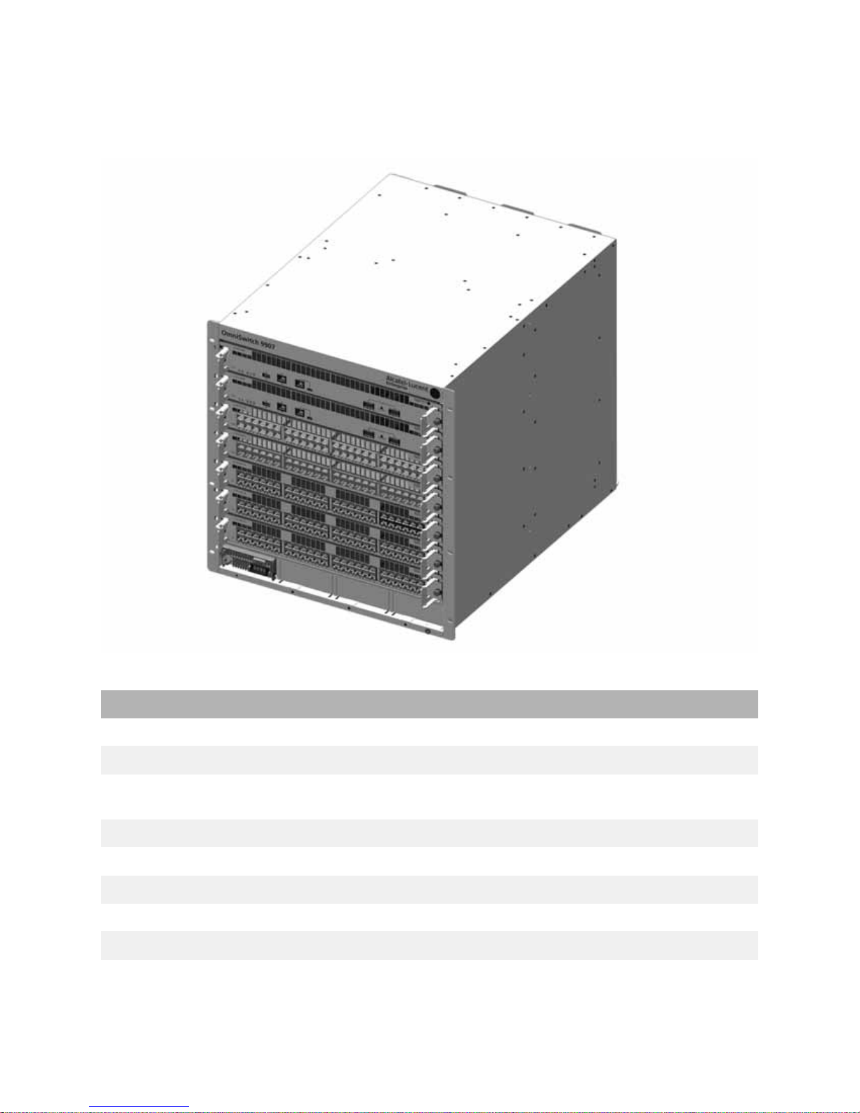
OmniSwitch 9900 Series
The Alcatel-Lucent Enterprise OmniSwitch 9907 11 RU modular LAN chassis.
OS9907 Chassis Specifications
Slots 7
Chassis Management Module (CMM) Slots 2
Chassis Fabric Module (CFM) Slots 4 (Slots CFM 3 and CFM 4 are currently inactive and are
Network Interface (NI) Slots 5
Fan Trays 3
Power Supplies 4
Rack Unit Dimensions 11 RU
Dimensions (HxWxD) 49.02 x 44.2 x 58.42 cm (19.3 x 17.4 x 23 in)
Weight (RCB) 32.83 kg (72.24 lb)
reserved for future use.)
3

OS9907 Chassis Specifications
Operating Temperature 0°C to 45°C (32°F to 113°F)
Storage Temperature 10°C to 70°C (14°F to 158°F)
Operating and Storage Humidity 10% to 90% (non-condensing)
Altitude 4000m/13,000 feet
4
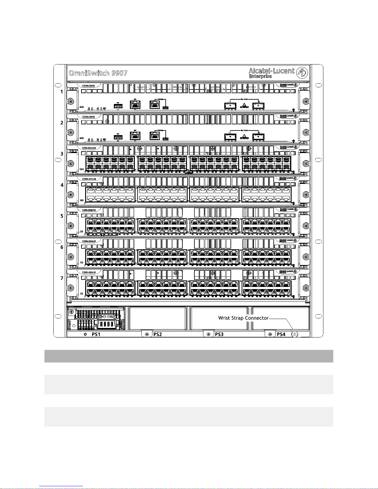
Chassis Front Panel
OS9907 Front Panel Components
Slot 1 Supports Chassis Management Module (CMM) only
Slot 2 Supports a CMM (for 1+1 CMM redundancy) or NI module
Slots 3 through 7 Support NI modules only
Slots PS1 through PS4 Support up to four load-sharing chassis power supplies,
Wrist Strap Grounding Connector Location shown in diagram above
(to maximize port count)
offering N+1 redundancy
5
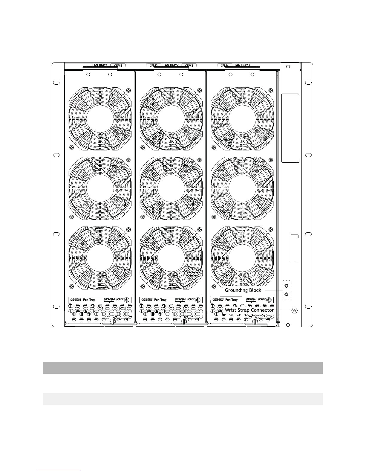
Chassis Rear Panel
Fan tray slot numbers are printed along the top-rear of the chassis.
OS9907 Rear Panel Components
Fan Tray Slots 1 through 3 Support three fan trays, with three fans per tray for N+1
Grounding Block Location shown in diagram above
Wrist Strap Grounding Connector Location shown in diagram above
fan redundancy
6
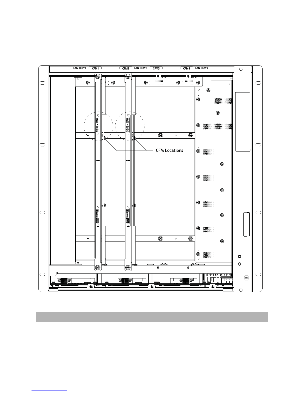
Chassis Rear Panel (Fan Trays Removed)
CFMs are located behind the chassis fan trays. To access a CFM, remove the fan tray in front of the
module. See “Removing Fan Trays” on page 50 for more information.
CFM slot numbers are printed along the top-rear of the chassis.
OS9907 CFM Location
Slots CFM1 through CFM4 For CFM module use only. Slots CFM1 and CFM2 are
currently supported; slots CFM 3 and CFM 4 are inactive
and reserved for future use
7
Chassis Management
92 1
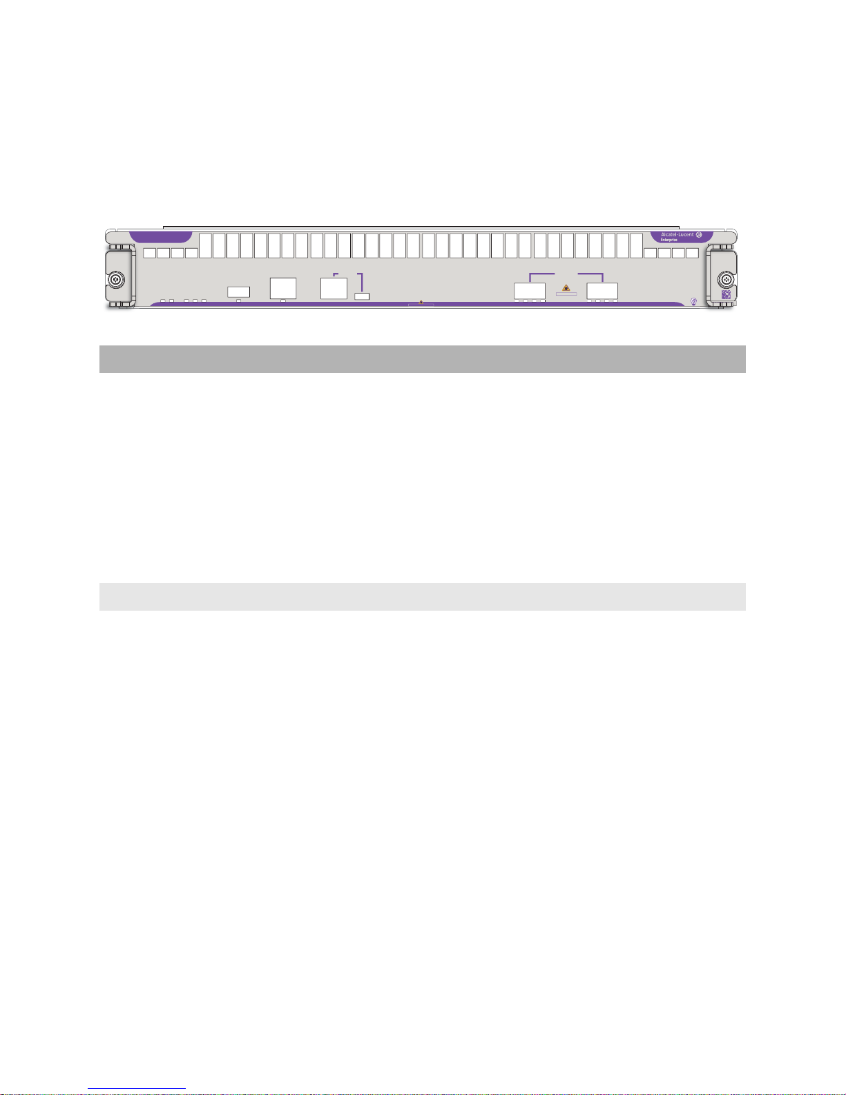
OS99-CMM
The CMM manages system functions in the chassis. This includes controlling and monitoring NIs, fabric
modules (CFMs) and power distribution. The CMM also provides two (2) 40G QSFP+ uplink ports.
OS99-CMM
40G
FAB PS
VC
PRI
USB
TEMP
EMP
CONSOLE
CLASS 1 LASER PRODUCT
VFL / UPLINK
12
ABC
CLASS 1 LASER PRODUCT
D
D
B
C
A
090992-10 C
CMM Specifications
Port Types (pictured from left to right) • USB Type A: For storage devices that can download
code or save configuration information, such as flashbased pen drives or external hard drives
• EMP (RJ45): 10/100/1000 Base-T with autonegotiation for out-of-band management (e.g.,
Telnet connection, diagnostics, downloading
software, etc.)
• Console (RJ45): For console or modem
• Console (Micro-USB*): For console or modem
• QSFP+ (Qty 2): 40G QSFP+ uplink ports
Power Consumption 64W
Number of Slots 2 (Slot positions 1 and/or 2. The slot 2 position may be
used for an NI module in lieu of a secondary CMM. Note
that, when an NI is installed in slot 2, CMM redundancy
is not provided.)
*Note. A driver is required for Micro-USB port operation. For information
on downloading the driver, refer to the OmniSwitch AOS Switch
Management Guide.
8

LEDs
Backlit Status LED Located at the module product name at the upper-left corner of
the front panel
• Solid Blue: HW OK
• Blinking Blue HW Bootup or HW Failure
Speed LED (40G) • Solid Green: HW OK
• Solid Red: HW Failure
• Blinking Green: SW OK (Heartbeat); the module is booted
and operating normally
• Solid Yellow: SW System Failure
PRI • Solid Green: CMM has Primary status
• Blinking Green: CMM has Secondary status
• Solid Yellow: CMM not operating
• Blinking Yellow: Software upgrade in progress
VC Virtual Chassis (reserved for future use)
FAB • Solid Green: Fabric modules (CFMs) operating normally
• Solid Yellow: Fabric module (CFM) error
PS • Solid Green: Power supplies are operating normally
• Solid Yellow: Power supply error
TEMP • Solid Green: System temperature is normal
• Solid Yellow: System temperature error (e.g., overtemp)
• Blinking Yellow: Fan error
USB • Solid Green: USB device/drive connected
• Blinking Green:USB device/drive transferring data
EMP • Solid Green: USB Port Link
• Blinking Green: USB Port Link and Activity
VFL/UPLINK Refer to “QSFP+ LED Display” below.
QSFP+
LED Display
Admin
Status
Link Status Transceiver Traffic VFL Port Speed
1G/10G (SFP+)
40G/4X10G
(QSFP+)
Off Down Down N/A N/A N/A N/A
Off Up Down No N/A N/A N/A
Solid Green Up Up Yes No No 10G (SFP+)
40G (QSFP+)
9

QSFP+
LED Display
Admin
Status
Link Status Transceiver Traffic VFL Port Speed
1G/10G (SFP+)
40G/4X10G
(QSFP+)
Solid Yellow Up Up Yes No No 1G (SFP+)
4X10G (QSFP+)
Solid BlueUpUpYesNoYesN/A
Blinking
Green
Blinking
Yellow
Blinking
Up Up Yes Yes No 10G (SFP+)
40G (QSFP+)
Up Up Yes Yes No 1G (SFP+)
4X10G (QSFP+)
Up Up Yes Yes Yes N/A
Blue
White N/A N/A Yes N/A N/A 4X10G
Note. Because OS99-CMMs provide splitter cable support on QSFP+ ports, port
LED behavior for these switches differs from other OS9900 modules. T o manually
configure network LED colors, refer to the interfaces beacon command in the
OmniSwitch AOS Release 8 CLI Reference Guide.
10
Switch Fabric
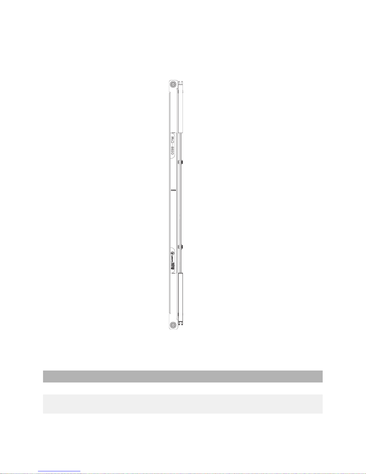
OS9907-CFM
Each OS9907-CFM installed provides 1280Gbps of switch fabric bandwidth to chassis management and
the Network Interface (NI) modules. The chassis provides four (4) OS9907-CFM slots. The modules
connect to the chassis mid-plane and are located just behind the system fan trays.
CFM Specifications
Switch Fabric Bandwidth 1280Gbps
Number of Slots 4 (Slots CFM 3 and CFM 4 are currently inactive
Power Consumption 119W
and are reserved for future use.)
11
NI Modules
10G
2
090990-10 C
24
25
13
12
37
36
48
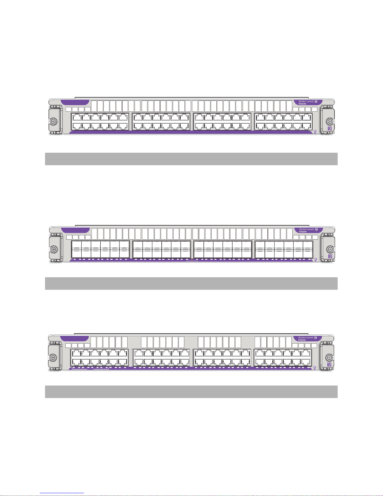
OS99-XNI-48
90 1CC
0 C0 0
10G
2
1
23
4
7
5
6
8
9 10
11
12
13
14 15
16 17 18
19
2021232224
25
26
27 28 29
333031
32
34 35
36 3738394041
42
43 44
45
46
47 48
090989-10 C
24
25
13
12
37
36
48
OS99-XNI-U48
89 1
0 CC0 C
0 C
0 C
0 C0 0 0 0
0
CLASS 1 LASER PRODUCT
1G
2
1
23
4
7
5
6
8
9 10
11
12
13
14 15
16 17 18
19
2021232224
25
26
27 28 29
333031
32
34 35
36 3738394041
42
43 44
45
46
47 48
090985-10 C
24
25
13
12
37
36
48
OS99-GNI-48
HPoE
85 1
0 CC0 C
0 C
0 C
0 C0 0 0 0
0
OS99-XNI-48
Port Type Number of Ports Power Consumption
1/10 GigE Base-T 48 402W
OS99-XNI-U48
Port Type Number of Ports Power Consumption
1/10 GigE SFP+ 48 305W
OS99-GNI-48
Port Type Number of Ports Power Consumption
10/100/1000 Base-T 48 56W
12
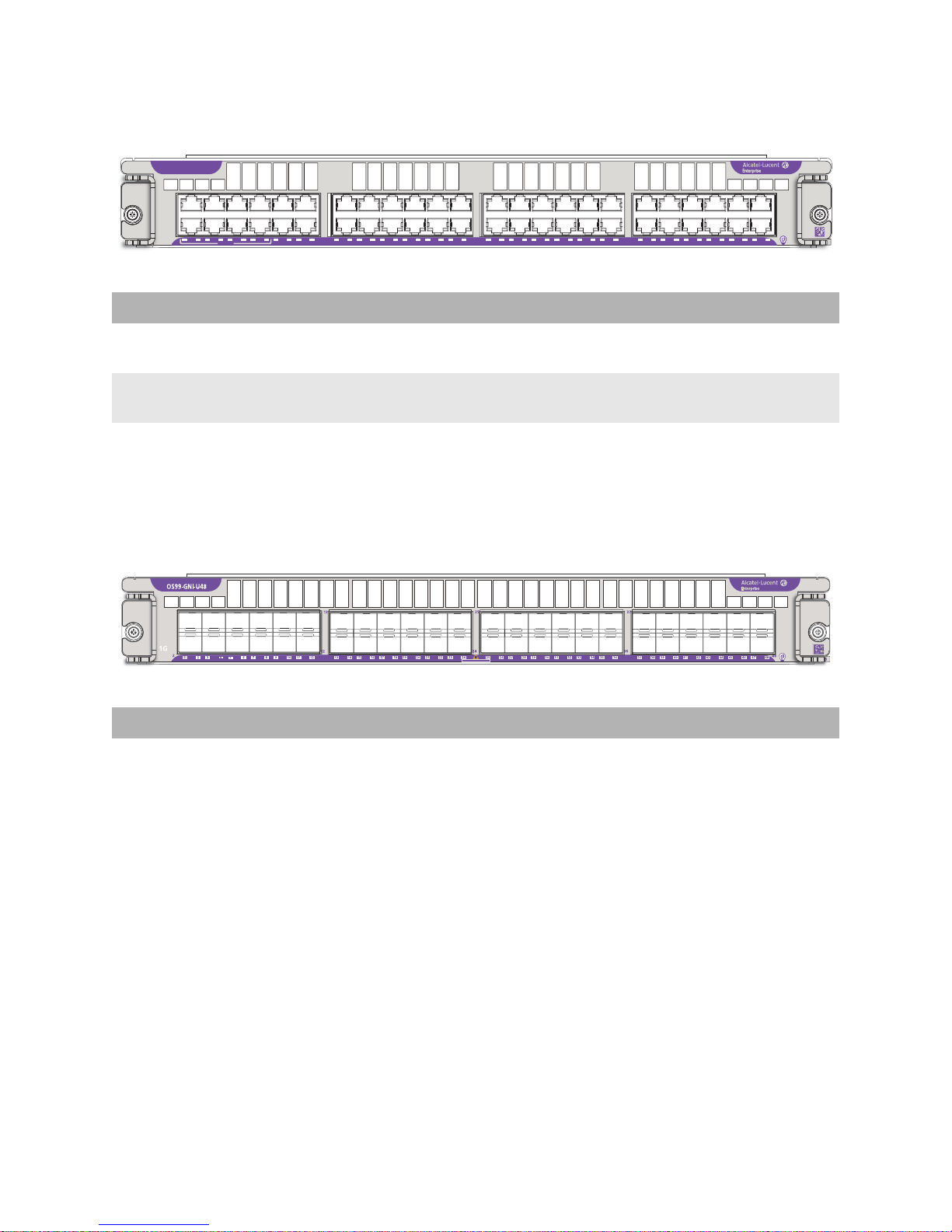
OS99-GNI-P48
86 1
0 CC0 C
0 C
0 C
0 C0 0 0 0
0
CLASS 1 LASER PRODUCT
CLASS 1 LASER PRODUCT
OS99-GNI-P48
13
25
37
1G
2
5
1
4
7
8
6
23
HPoE
9 10
12
11
13
12
14 15
16 17 18
19
2021232224
24
26
27 28 29
25
333031
32
36
34 35
36 3738394041
43 44
45
47 48
46
42
48
Port Type Number of Ports Power Consumption
10/100/1000Base-T PoE 48 54W, excluding any attached
Powered Devices (PDs)
HPoE Ports Ports 1 through 8 support HPoE (75W). These ports are labeled
“HPoE” on the chassis front panel.
OS99-GNI-U48
090986-10 C
Port Type Number of Ports Power Consumption
1 GigE SFP 48 70W
13

NI Module LEDs
NI Module LEDs
Backlight Status LED Located at the module product name at the upper-left corner of
the front panel
• Solid Blue: HW OK
• Blinking Blue HW Bootup or HW Failure
Speed LED Located at the left side of the front panel and indicates the
maximum port speed for the module (e.g., 10G)
• Solid Green: HW OK
• Solid Red: HW Failure
• Blinking Green: SW OK (Heartbeat); the module is booted
and operating normally
• Solid Yellow: SW System Failure
Power Save LED Reserved for future use
Port Status LEDs • Solid Green: Non-PoE Port Link
• Blinking Green: Non-PoE Port Link and Activity
• Solid Yellow: PoE Port Link (PoE modules only)
• Blinking Yellow: PoE Port Link and Activity (PoE modules only)
14
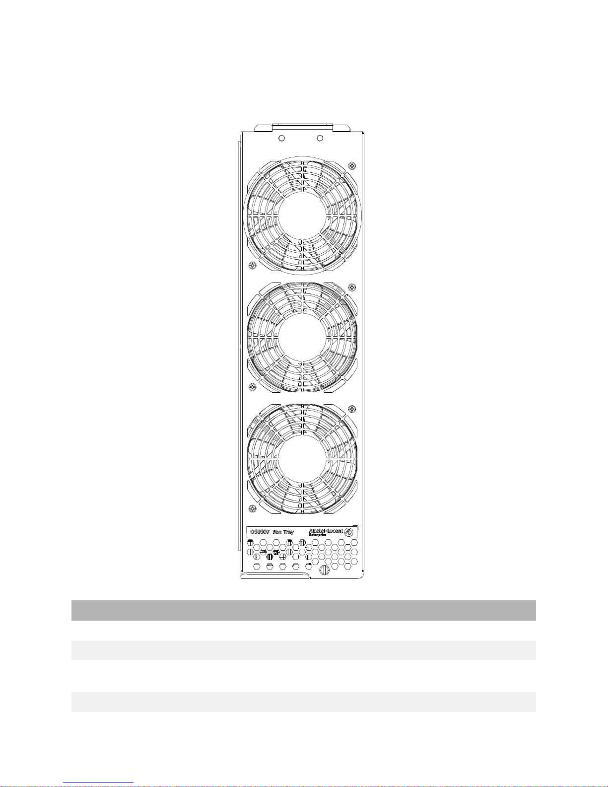
Fan Trays
The chassis provides three (3) fan tray slots for chassis air and temperature control.
Fan Tray Specifications
Number of Fan Tray Slots 3 (with three fans per tray for N+1 fan redundancy)
Airflow Direction Front-to-back only
Hot Swapping Supported (Three fan trays are required at all times; removal of a
Power Consumption 112W
fan tray is allowed for fan tray or CFM field replacement only.)
15
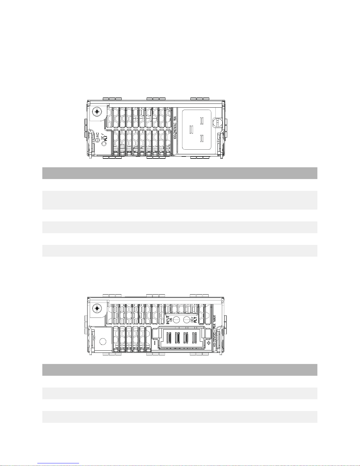
Power Supplies
Note: Mixing of AC and DC power supplies is not supported. Mixing of Hi
(240VAC) and Low (110VAC) input is not supported.
OS99-PS-A (AC Power Supply)
OS99-PS-A Specifications
Input Voltage/Current 100 VAC (13.8A) to 240V AC (16.5 A)
Max Output Power/Current 1200 W/21.4 A
3000 W/53.5 A
Dimensions 1.63 in x 4 in x 17.2 in
Weight 4.8 lb (2.18 kg)
Hot Swapping Supported
Provides Power for System and PoE
OS99-PS-D (DC Power Supply)
OS99-PS-D Specifications
Input Voltage/Current -40 VDC to -72 VDC / 75 ADC (At input voltages > 40 VDC)
Max Output Power 2500 W (44 - 58 VDC)
Max Output Current 44.6 A @ 56 VDC
Dimensions 1.63 in x 4 in x 17.2 in
16

OS99-PS-D Specifications
Weight 4.6 lb (2.1 kg)
Hot Swapping Supported
Provides Power for System and PoE
17

DC Power Supply Connection
Connecting a DC Cable Harness to the Chassis Power Supply
When plugging in the cable, insert the connector end of the cable harness into the power supply
connector until it clicks firmly into place. This is an indication that the connector is secure and properly
seated.
Connecting a DC Cable Harness to the DC Power Source
The other end of the cable harness is bare. Users must assemble and connect this end to the DC power
source or to a cable coming from the power source. In addition to following the important guidelines
listed below, be sure to consult manufacturer specifications for the DC power source before starting.
• Connect the power supply to a reliably grounded 48V or 60V SELV source.
• The branch circuit overcurrent protection must be rated 75A.
• Use two 10 AWG copper conductors.
• A readily accessible disconnect device that is suitably approved and rated shall be incorporated in
the field wiring.
• The above product(s) shall be installed in a restricted access location.
• The power supply shall used with an 4P PWRBLADE CONNECTOR, FCI model 10080598-2ED0006LF.
CAUTION: Installation of a DC cable that is more than 3 meters in length is
subject to LOCAL CODES and AUTHORITIES. Please contact your electrician and
the Local AHJ (Authority Having Jurisdiction) to follow the Electrical Codes
before use of proper installation methods.
18
 Loading...