

Page 1
User Manual
8 Channel PMR 446
handheld 2-way radio
Tec
talk
1
Page 2
OPERATING INSTRUCTIONS
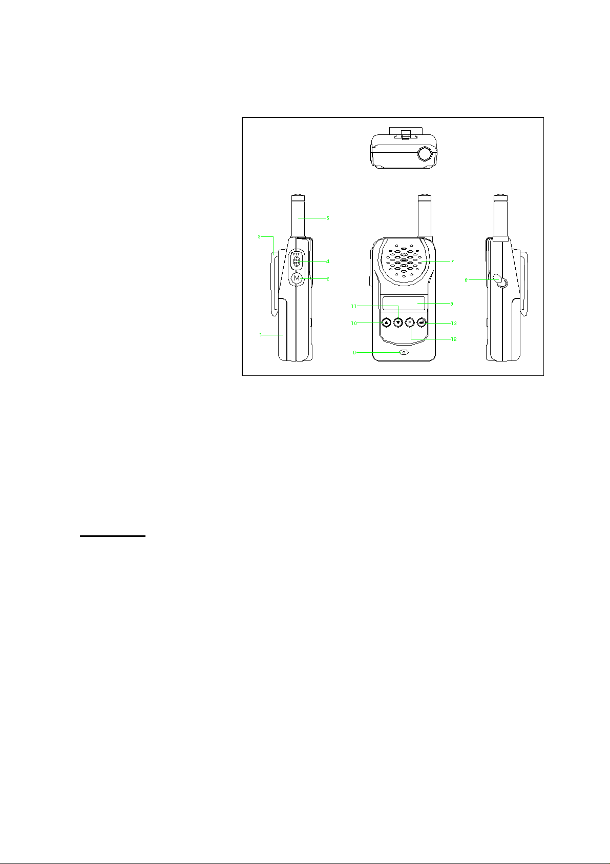
FUNCTIONS AND CONTROLS
1. Battery Door
2. Monitor Button
3. Detachable Belt Clip
4. Push-To-Talk (PTT) Button
5. Antenna
6. External Mic / Speaker
7. Built-in Speaker
8. LCD Panel
9. Built-in Microphone
10. Up Button & Volume Control
11. Down Button & Volume
Control
12. Function Button
13. Power On/Off & Enter Button
BATTERY INSTALLATION
Each Communicator unit operates on four ‘AAA’ size batteries.
1. Remove the Battery Door (#1) from the back cabinet by unclipping the lock at the bottom of the
door and lifting it upwards.
2. Following the polarity diagram shown inside the battery compartment, insert four ‘AAA’ size
batteries. Replace the
Battery Door (#1) and lock.
IMPORTANT:
3. For better performance and longer operating time, we recommend the use of alkaline-type
batteries.
4. Do not mix old and new batteries.
5. Do not mix alkaline, standard (carbon-zinc) or rechargeable (Ni-MH) batteries.
6. If the unit is not to be used for an extended period of time, remove the batteries. Old or leaking
batteries can cause damage to the unit and will void the warranty.
WRIST STRAP AND DETACHABLE BELT CLIP INSTALLATION
The Wrist Strap and Detachable Belt Clip are provided to enable you to carry the
palm-sized Communicator easily and safely.
1. To use the Wrist Strap, simply attach it to the hole just above the Belt-clip (#3). Feed the small
loop on the end of the strap through the hole and then pass the strap through the loop and pull
tight.
Be sure that the batteries are installed correctly. Wrong polarity may damage
the unit.
2
Page 3
2. The Detachable Belt Clip is already attached to your Communicator and locates into the slot on
the back of the unit. If you want to remove the belt clip, press the locking lug at the top away
from the unit and slide the belt clip upwards to remove. To re-install, just slide the belt clip into
the slot and snap in place.
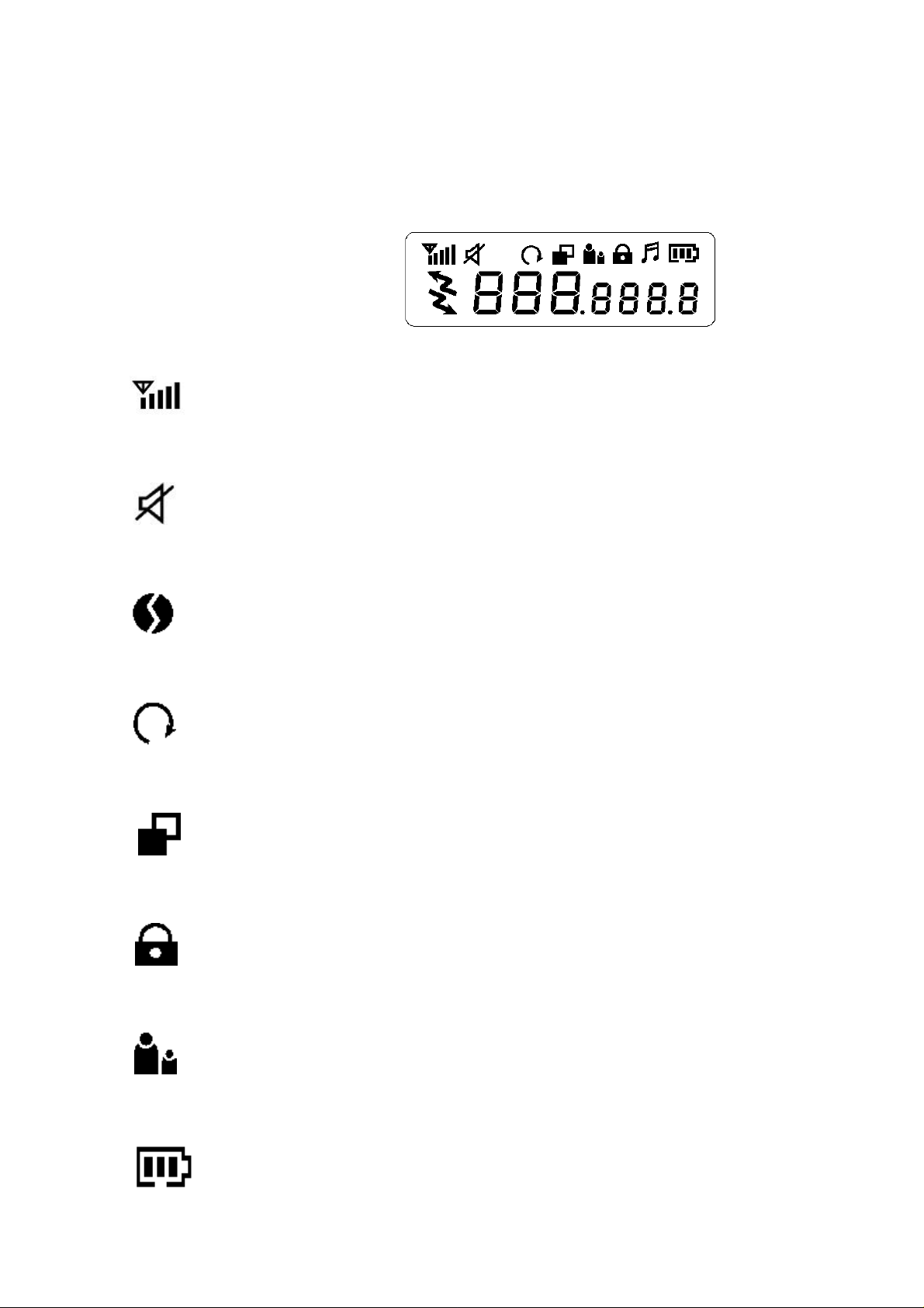
LCD PANEL ICON DESCRIPTIONS
1. RSSI (Receiving Signal Strength Indicator) or TX Bar Icon
Indicates the receiving signal strength and blinks during transmission.
2. Monitor Indicator
Appears when the monitor button is used.
3. CTCSS Indicator
Appears when the correct CTCSS tone is entered.
4. Auto Channel Scan Indicator
Appears in the auto scan mode or when the auto scan mode is activated.
5. Dual Watch Scan Indicator
Blinks in dual watch scan mode or Appears when the dual watch scan mode is activated.
6. Key Lock Indicator
Blinks in auto lock selection mode or Appears when the key lock is activated.
7. VOX Indicator
Blinks in VOX selection mode or appears when VOX is activated.
8. Battery Level Indicator
3
Page 4

Battery Level Meter indicates the remaining battery strength. If a battery becomes too weak
for transmit operation, You will be warned additionally by flashing the red LED every 5
seconds. At a too weak battery state the CPU may switch off the TX operation for some
seconds to allow the batteries to recover.
9. Power Save Display
Blinks when the power save is activated. The rate at which the icon blinks varies with the
power saving ratio. Fast indicates a lower power saving while slow indicates a higher power
saving ratio.
10. Tx Indicator
Appears when a signal is being transmitted.
11. Rx Indicator
Appears when a signal is being received.
12. Large Segment Display
Indicates the channel number in use at the normal mode. When the Function Button is
pressed, it displays the function menu in sequence: CH / cTc / SC / dW / VO / Vdt / ALo /
CAL / ton
13. Small Segment Display
Displays the CTCSS tone option at the normal mode. CTCSS option is displayed in “Hz”.
Displays the SUBMENU of each MENU in the function mode. (e.g. CH 1-8 / cTc: hz / SC: up,
dn / dW: channel number / VO: high, off, low / Vdt 5sec, 3sec, 2sec, 1sec / ALo off, auto /
CAL number 1-7 / ton : no - freq )
CONTROL BUTTON FUNCTIONS
Power ON/OFF (#13)
•
•
ENTER BUTTON (#13)
Press it to confirm the required option for respective functions during function edit mode.
Press it briefly in standby mode to convert the display of CTCSS sub code from frequency to
Power On - Short Touch
Press this button (#13) briefly to turn the unit on. A short confirming melody will play.
Power Off - Long Touch
Press this button (#13) for longer than 1.5 seconds to turn the unit off. A short confirming
melody will play.
( ↵ )
( ↵↵ )
4
Page 5

number or number to frequency in about 1 second.
PUSH-TO-TALK (PTT) BUTTON (#4)
1. Press it firmly and speak into the Built-in Microphone (#9) to transmit. The red Tx LED
Indicator at the right side of the LCD Panel (#8) will light.
2. Release it to revert to standby mode. When an incoming call is received, the green Rx LED
Indicator on the left side of the LCD Panel (#8) will light.
3. 2-Way Call Ringer: Press the PTT Button twice quickly to call another party on the same
channel. The word “CALL” and the Tx icon will appear in the display. The user selected call
ringer melody will play (see page 6 to change call melody). The Call melody can be switched
off with the same menu step to avoid accidential activation.
VOLUME CONTROL (#10
In the standby mode, adjust volume to a comfortable level by pressing the UP (#105) & the
DOWN
UP
•
•
DOWN
•
•
button (#116) and adjusting the volume control at the same time.
BUTTON (#10)
Short Touch
In the standby mode, press this button briefly to move to the next higher main volume level.
In the function edit mode, press briefly to shift from the current option in each submenu to the
next option in the same submenu.
Long Touch
Pressing this button for more than 1.5 seconds will allow you to navigate at a more rapid rate
through different volume level in the standby mode or through different menus in the function
edit mode.
BUTTON (#11)
Short Touch
In the standby mode, press this button briefly to move to the previous lower main volume
level.
In the function edit mode, press briefly to shift from the current option in each submenu to the
previous option in the same submenu.
Long Touch
Pressing this button for more than 1.5 seconds will allow you to navigate at a more rapid rate
through different volume level in the standby mode or through different menus in the function
edit mode.
( 5)
( 6)
(55)
& #11
(66)
)
FUNCTION
•
Press this button briefly to enter function edit mode in standby mode.
Long Touch
•
Press for longer than 1.5 seconds to activate or deactivate the KEY LOCK in the standby
mode. Please note all buttons will be disabled except the Monitor Button (#2) and PTT
Button (#4) will remain fully operational (see menu description to activate and disable the
auto key lock function).
MONITOR BUTTON (#2) (=disable automatic squelch)
Press it to check activity on the current channel before you try to transmit.
•
BUTTON (#12)
Short Touch
( F )
5
Page 6

You can use the Monitor button when You receive weak or interrupted signals. If You press
•
Monitor only for a short time, the squelch opens for the time pressed.
If You press the button longer than 7 seconds continuously, the squelch will remain open. You
•
may use this function if Your distant party’s signal remains weak for a longer time period.
Pressing again Monitor closes the squelch again.
•
Adjust the Volume Control (#10 5& #116) if necessary.
•
Other functions of the monitor button
When you press the Monitor Button, the LCD Panel (#8) will be illuminated with an amber
•
color back-light and both the Tx and Rx LED Indicators will light. After some seconds the LED
will switch off again.
If you press the Monitor Button during the function edit mode, you will return to standby mode
•
directly.
In the Auto channel scan mode, if you press it during Rx or scan wait time (about 5 seconds)
•
in specific channel, it skips the channel in the auto channel scan after that.
If You press Monitor longer during SCAN mode until You hear a beep tone, the channel will be
•
skipped during all following scan cycles, as long as scanning remains activated.
When you press it during VOX operation, discontinue it in about 10 seconds.
•
EXTERNAL MIC/SPEAKER
This jack accepts an optional headset/microphone for totally handsfree operation. Please refer to
the latest Albrecht accessory item listen in catalogue or internet (www.albrecht-online.de) or ask
Your dealer.
OPERATION / FUNCTION EDIT MODE
2. CHANNEL SELECT MODE
This feature allows you to select main channels to communicate with the party.
To access the Channel Select Mode,
Press the Function Button (#12) until “CH” appears in the LCD Panel (#8).
-
Press the Up Button (#10) or the Down Button (#11) to choose channels up or down from
-
the current channel
number.
Press the Enter Button (#13) to confirm your selection.
-
3. CTCSS (Coded Tone Controlled Squelch System) SUBCHANNEL SELECTION MODE
This feature allows you to utilize a less used channel range (00-38) within a main channel.
This enables you to communicate with another party on the same main channel using the
same subcode. This helps to avoid congestion on the main channel and filters out unwanted
noise and static. There are 38 CTCSS subchannels for each main channel.
To change the CTCSS subchannel,
Press the Function Button (#12) until the word “cTc” appears in the LCD Panel (#8).
-
Press the Up Button (#10) or the Down Button (#11) to choose the desired subchannel to
-
use. The corresponding subcode frequency will be displayed in the lower right corner.
Press the Enter Button (#13) to confirm your selection.
-
(#6)
NOTE
: To communicate with other PMR units, they must be switched to the same
channel and CTCSS subcode. To communicate with other PMR units that do not have
subcodes, switch your unit to the same channel with the subcode set to “OFF”.
6
Page 7

4. AUTO CHANNEL SCAN MODE
This feature allows you to scan for an active channel and communicate with the party
transmitting.
To access the Auto Channel Scan menu,
Press the
•
Function
LCD Panel (#8).
Press the Up Button (#10) or the
•
current channel number.
Press the
•
The unit will begin scanning for an active main channel. If a transmission is detected, the Rx
•
Enter
and RSSI icons will appear in the LCD Panel (#8).
To turn off the auto channel scan feature in the standby mode, simply press the
•
Button (#12) once.
Continuously busy or undesired channels can be skipped from scanning after scanner has
•
stopped on such a channel by pressing the
Short pressing: channel will be skipped immediately for the same scan cycle
•
Long pressing (until You hear beep tone): channel will be skipped for all further scan cycles,
•
as long as scanning remains activated.
5. DUAL WATCH SCAN MODE
This feature allows you to monitor two different channels at the same time. If you pre-set any
priority channel other than the current channel in use, the pre-set channel will be scanned
every 0.5 second and signals you when a call is received.
To access the Dual Watch scan menu,
Press the
•
Function
LCD Panel (#8).
Press the
•
Up
you wish to closely monitor.
Press the
•
To turn off the dual watch feature in the standby mode, simply press the
•
Enter
(#12) once.
6. VOX SELECTION MODE
The Voice Activated Transmission (VOX) function allows your voice to activate transmission
automatically when the Communicator is used with the optional handsfree mic/headset (refer
to enclosed Accessory Order Form). It also allows handsfree use when a mic/headset is not
being used without having to use the PTT Button (#4). The Vox menu allows not only
different vox sensing trigger levels, but is even coupled with automatic MIC sensitivities
dependimg on the surrounding noise conditions.
To access the VOX Selection menu,
Press the Function Button (#12) until the
•
Panel (#8).
Press the Up Button (#10) or the Down Button (#11) to select from
•
High, Mid or low setting determines
surrounding noise
Button (#12) until the auto channel icon blinks and “SC” appears in the
Button (#11) to choose scanning up or down from the
Down
Button (#13) to confirm your selection.
MONITOR
button:
Button (#12) until the dual watch icon blinks and “dW” appears in the
Button (#10) or the
Button (#11) to select the desired channel number
Down
Button (#13) to confirm your selection.
Function
icon blinks and “UO” appears in the LCD
VOX
High, Mid, low
VOX and mic
response sensitivity. While High is for
, this position has the lowest sensitivity and is designed for louder
Function
Button
or
OFF.
high
7
Page 8

speaking volules in such a high noise surrounding (preferable for
For
•
•
•
baby monitoring
Press the Enter Button (#13) to confirm your selection.
To turn off the VOX feature, enter the VOX selection mode and then select “
use
position for highest sensitivity in the baby’s room.
LOW
motor bike drivers
OFF
)
’’.
7. VOX RECOVERY TIME SELECTION MODE
This allows the response characteristics of the VOX function to be precisely adjusted to suit
individual needs.
To access the VOX Recovery Time Selection menu,
Press the
•
Function
Button (#12) until “
” appears in the LCD Panel (#8) with the VOX
Udt
icon blinking.
Press the Up Button (#10) or the
•
Down
Button (#11) to select from 5, 3, 2 or 1 second setting.
This setting determines the delay time between transmitting and receiving.
Press the
•
Please note you may need to try different VOX time settings to determine the best value to
•
Enter
Button (#13) to confirm your selection.
suit your speaking habit.
To turn off the VOX feature, enter the VOX selection mode and then select “
•
Off
’’.
8. AUTO KEY LOCK SELECTION MODE
This feature prevents accidental channel change and disturbance to the preferred settings of
the Communicator. Auto Key Lock temporarily disables the Up, Down and Enter Buttons.
To access the Auto Key Lock Selection menu,
Press the
•
Function
Button (#12) until the auto lock icon blinks and “
” appears in the
ALo
LCD panel (#8).
Press the Up Button (#10) or
•
Press the
•
If you do not press any key for more than 15 seconds in the standby mode, all respective
•
ENTER
key to confirm your selection.
Button (#11) to select the “Auto” option.
Down
keys will automatically be locked.
To turn the auto key lock on or off in standby mode, simply press and hold the Function
•
Button (#12) for more than 1.5 seconds.
To quickly activate the Key Lock, hold the Function Button (#12) for more than 1.5 seconds.
•
9. CALL RINGER MELODY (and Call OFF) SELECTION MODE
This feature provides 7 user selectable call ringer melodies to alert you of a calling party.
To select your favorite Call Ringer melody,
Press the Function Button (#12) until the call icon blinks and “
•
” appears in the LCD
CAL
panel (#8).
Press the Up Button (#10) or Down Button (#11) to preview the
•
select
Press the
•
CAL OFF
, if You do not desire to have this function (recommended for motor bike use).
ENTER
key to confirm your selection.
7 available melodies
10. CTCSS SUB CODE DISPLAY SELECTION MODE
To select your favorite CTCSS sub code display, press the button in standby mode.
or
8
Page 9

10. Beep tone switching
There is also a menu point which allows deactivation of the key beep tones. Beep tones are
good with loudspeaker operation, but should be switched off during ear phone operation.
Press the Function Button (#12) until the call icon blinks and “
•
bEp ON
” appears in the LCD
panel (#8).
Press the Up Button (#10) or Down Button (#11) to select between
•
bEp ON and bEp OFF
use).
Press the
•
ENTER
key to confirm your selection.
11. Squelch tail noise elimination
A software switch can reduce the disturbing noise which happens after a distant party stops
transmission and releases the PTT button. The elimination function can be enabled among
tectalk models only and can reduce the noise burst in receive mode. Technically, the
transmission stop will be delayed for about 400 mseconds after releasing the PTT button.
The effect will be optimized together with CTCSS use.
Press the
•
Function
Button (#12) until the call icon blinks and “
t Al OFF
” appears in the LCD
panel (#8).
Press the Up Button (#10) or
•
Press the
•
ENTER
key to confirm your selection.
Button (#11) to select between
Down
tAl OFF or tAl ON
.
NOTES FOR GOOD COMMUNICATION
1. Your Communicator unit’s 8 channels are shared on a “take turns” basis. This means other
groups may be talking on any of the channels. A common code of ethics/courtesy is to
switch to another vacant channel and not to attempt to talk over someone who is already
using the channel you first selected.
2. Your Communicators have been designed to maximize performance and improve
transmission range in the field. To avoid interference, it is recommended that you do not use
the units closer than 5 feet apart.
3. For best transmission results, always keep your mouth about 2-3 inches from the
Microphone (#9) and speak slowly in a normal voice.
CARE AND MAINTENANCE
Clean your unit with a damp (never wet) cloth. Solvent or detergent should never be used.
•
Avoid leaving your unit in direct sunlight or in hot, humid or dusty places.
•
Keep your unit away from heating appliances and sources of electrical noise such as
•
fluorescent
lamps or motors.
SPECIFICATIONS
Operating Main Channels 8 CH (European international agreement)
CTCSS Subchannels 38 for each main channel
Operating Frequency Range UHF 446.00625MHz to 446.09375 MHz
Talk Range Up to 2 –3 miles / 5 km
Output Power 0.5 Watts max
Power Source ‘AAA’ alkaline batteries X 4, 6 VDC
9
Page 10

NiMH Rechargeable Battery AAA X 4, 4.8VDC
Battery Life About 35 hours (5/5/90 duty cycle)
MAIN CHANNEL FREQUENCY TABLE (in MHz)
Main
Channel No.
1 446.00625
2 446.01875
3 446.03125
4 446.04375
5 446.05625
6 446.06875
7 446.08125
8 446.09375
Frequency
(in MHz)
CTCSS SUBCHANNEL FREQUENCY TABLE (in Hz)
CTCSS
Subchannel No.
1 67.0 20 131.8
2 71.9 21 136.5
3 74.4 22 141.3
4 77.0 23 146.2
5 79.7 24 151.4
6 82.5 25 156.7
7 85.4 26 162.2
8 88.5 27 167.9
9 91.5 28 173.8
10 94.8 29 179.9
11 97.4 30 186.2
12 100 31 192.8
13 103.5 32 203.5
14 107.2 33 210.7
15 110.9 34 218.1
16 114.8 35 225.7
17 118.8 36 233.6
18 123.0 37 241.8
19 127.3 38 250.3
Frequency
(in Hz)
CTCSS
Subchannel No.
Frequency
(in Hz)
CARE AND SAFETY
To assure optimal radio performance and to ensure RF energy exposure is within the guidelines
of the above standards, the following operating procedures should be observed:
FOR PORTABLE 2-WAY RADIOS
When transmitting with a portable radio, hold radio in a vertical position with its microphone 1-
•
2 inches away from your mouth. Keep antenna at least 1 inch from your head and body.
10
Page 11

If you wear a portable radio on your body, ensure the antenna is at least 1 inch from your body
•
when transmitting.
ELECTROMAGNETIC INTERFERENCE / COMPATIBILITY
Most electronic devices are susceptible to electromagnetic interference (EMI) if inadequately
shielded, designed or otherwise configured for electromagnetic compatibility.
Turn off your radio in any facilities where posted notices instruct you to do so. Hospitals or
•
health care facilities may be using equipment that is sensitive to external RF energy.
Turn off your radio when on board aircraft when instructed to do so. Any use of the radio must
•
be in accordance with airline regulations or crew instructions.
•
CAUTION
Damaged Antenna
Do not use any radio with a damaged antenna. If a damaged antenna comes in contact with the
skin, a minor burn may result.
Batteries
Do not short circuit exposed terminals of any batteries with any conductive materials. In doing so,
the material may become quite hot and cause property damage and/or body injury such as burns.
WARNING
Parts Replacement or Substitution
Replacement or substitution of parts other than those recommended by CP Tech may cause a
violation of the technical regulations of the ETS-300-296 Rules, or violation of Type Acceptance
requirements of the ETS-300-296 Rules.
Vehicles with an Air Bag
Do not place a portable radio in the area over an air bag or in the air bag deployment area. Air
bags inflate with great force. If a portable radio is placed in the air bag deployment area and the
air bag inflates, the radio may be propelled with great force and cause serious injury to occupants
of vehicle.
Potentially Explosive Atmospheres
Turn your radio off when in any area with a potentially explosive atmosphere, unless it is a type
especially qualified for such use. Sparks in such areas could cause an explosion or fire resulting
in body injury or even death.
Batteries
Do not replace or charge batteries in a potentially explosive atmosphere. Contact sparking may
occur while installing or removing batteries and cause an explosion.
11
Page 12

Charging Well
Blasting Caps and Areas
To avoid possible interference with blasting operations, turn your radio off near electrical blasting
caps or in a “blasting area” or in areas posted:” Turn off 2-way radio”. Obey all signs and
instructions.
Areas with potentially explosive atmospheres are often, but not always, clearly marked.
Note:
They include fuelling areas such as below deck on boats, fuel or chemical transfer or storage
facilities; areas where the air contains chemicals or particles, such as grain, dust, or metal
powders; and any other area where you would normally be advised to turn off your vehicle engine.
Accessory – Desktop Charger
After removing the charger base and power supply from the packaging, plug the power supply’s
DC connector into the jack on the back of the base.
To charge a battery, simply place the radio into the front charging well. Cycle lasts up to 10 hours.
As option, a 12 V DC cable for Car use is available. This will allow charging the radio from car 12
V supply.
D.C Power Jack
European 2 years warranty
The distributor, dealer or retail shop warrants to the original retail purchaser of this product that should this
product or any part of it, under normal use and conditions, be proven defective in material or workmanship
within 2 years from the date of original purchase, such defect(s) will be repaired or replaced with new or
reconditioned product (at the company's option) without charge for parts and repair labor. To obtain repair
or replacement within the terms of this warranty, the product is to be delivered with proof of warranty
coverage (e.g. dated bill of sale), specification of defect(s), to the distributor, dealer or his authorized
repair center.
The Company disclaims liability for communications range of this product. The warranty does not apply to
any product or part there of which, in the opinion of the company, has suffered or been damaged through
alteration, improper installation, mishandling, misuse, neglect, accident, or by removal or defacement of
the factory serial number/bar code label(s). The warranty does not apply to accessory parts or problems
caused through not authorized or not recommended accessories like of the units like batteries, external
power supplies and over voltage caused through external power supplies, light bulbs, broken antennas,
broken swivel belt clips, broken or damaged acrylic glass windows and cabinet parts.
Please contact the dealer or person where You have purchased Your Tectalk.
12
Page 13

Where to find service hints and documentation
The complete technical documentation is updated regularly. You can download the latest versions of user
manuals, technical documents and conformity declaration, as well as service hints or FAQ’s any time from
our server under
http://www.albrecht-online.de/service
If You should have a problem, please have a look to the service hints or frequently asked questions (FAQ)
before You send Your Tectalk back to the service center.
CE- Declaration of Conformity
Albrecht Tectalk / JDP-408 HX
This unit complies to all relevant European Standards and Regulations for PMR 446 radio service. This
radio may be used only in EU countries and some other states applying the R&TTE directive of the
European Community. However, there are still some restrictions (as of date of this user manual) to use
PMR 446 in following countries:
Italy and Norway:
France:
Belgium:
Eastern Europe
This unit fully complies to the following European standards
notified body 0499
this radio. The unit is intended to be used in following European countries:
A, B, CH, CZ, D, DK, E, F, FIN, GB, GR, H, HR, IS, IR, L, NL, P, S, TR (JDP-408HX)
Lütjensee, 13.05.2002
ALAN Electronics GmbH
The latest actual version of our „EC Declaration of Conformity“ may be downloaded from our Internet
Note:
server under
© ALAN Electronics GmbH (05-2002)
www.albrecht-online.de
service-hotline: (+49) 4154 849 180
service-fax: (+49) 4154 849 288
service-e mail: service@albrecht-online.de
PMR 446 is not yet established in these countries. Other radio services are still
legally using these frequencies. Travellers may take the radios with them, but
not operate them. Please ask local authorities for further informations!
Channels 1 and 2 are not yet allowed to be used.
No restrictions for travellers using the radio in Belgium free of charge and
licence for less than 3 months.
operating licence according to Belgian regulations.
Please ask the local authorities before using the radio, because only few
countries outside EU apply already the european R&TTE directive. Following
countries still apply special national approval regulations, not (yet) valid for PMR
446 radio
Slowenia and some others.
(SEE Luxembourg) had been involved for the expert’s opinion about the conformity of
http://www.albrecht-online.de/service
Poland
, Estonia, Letavia, Lithuania, Ukraine, Russia, Belarus,
Residents of Belgium
ETS 300 296, ETS 300 279, EN 60 950
.
must apply for a radio
. The
13
Page 14

Technische Information
Probleme mit den Ladekontakten beim Tectalk/Sporty Space
Der in der Produktion gewählte Anschlußpunkt des Bodenkontakts zwischen R 120 und D 25/26
(im Schaltbild nicht eingezeichnet!) führt unter bestimmten Umständen zu Problemen:
De Facto ist der Ladeanschluß über 120 Ohm (R 120) ständig parallel zum Mikrofoneingang
geschaltet!
Diese Schaltung hat folgenden Einflüsse:
1.Bei Anliegen von Ladespannung ist kein Mikrofonbetrieb möglich (z.B. Babysitter bei
gleichzeitigem Einsetzen in Ladeschale, kein gleichzeitiger Ladebetrieb und Betrieb über
Headset)
2. Bei Wegfall der Ladespannung hat die Ladebuchse volle NF-Empfindlichkeit und wirkt
wie ein Mikrofonanschluß inc. PTT Taste. Man kann sogar ein Mikrofon an die Ladeschale
einstecken und das funktioniert. Fatale Folge: Mit einem Auto-Ladekabel, das keine
Sperrdiode hat, wirkt das Autonetz bei abgeschalteter Zündzung wie eine PTT-Taste und
führt zu Dauersenden.
Lösung:
Es wird vorgeschlagen, den 120 Ohm Widerstand (R 120, leicht zu finden neben der
Mikrofonbuchse, zu entfernen. Dann ist die wenig nützliche Stromverbindung zur Mikrofonbuchse
unterbrochen, Laden über Mikrobuchse geht dann zwar nicht mehr, aber das hat Albrecht auch
nie propagiert.
gez. 14.4.2000 W. Schnorrenberg/Albrecht
Page 15

Service Hints for Tectalk/ Servicehinweis Tectalk
1. Squelch adjustment /Squelcheinstellung
Due to low parts tolerances, normally a squelch threshold point adjustment will not be
necessary. In case of tolerance problems, the squelch closing point can only be adjusted
by changing the value of R 18.
Normalerweise braucht der Squelch wegen geringer Teiletoleranzen keine veränderbaren
Einstellelemente (z.B. Trimmpoti). Sollte jedoch im Service das Problem bestehen, dass
z.B. der Squelch nicht öffnet oder andauernd offen bleibt, kann durch Verändern von
R 18 der Schaltpunkt verschoben werden.
R 18
Position
Page 16

The following drawing shows where to find R 18 on the printed circuit board.
Position of
Auf der folgenden Zeichnung sieht man die Lage des Widerstands R 18
R 18
2. CPU-Reset
In the case that the CPU hangs or LCD shows abnormal digits, the CPU can be reset:
Switch off unit, press and keep UP and F button pressed, switch on unit and release all
buttons.
Für den Fall, dass die CPU blockiert (keine Reaktion auf Tastendruck oder
ungewöhnliche Anzeigen), kann die CPU wie folgt zurückgesetzt werden: Gerät
ausschalten. Auf und F-Taste gleichzeitig drücken und festhalten. Bei gedrückt
gehaltenen Tasten Gerät wieder einschalten und alle Tasten wieder loslassen.
Page 17

Reset-Möglichkeiten für Tectalk, Tectalk FM:
Tasten zusammen drücken und gedrückt halten, bis sich das
-
in der
erät eingeschaltet hat.
enutzer vorher gespeicherte
(Power) button at the same time while
hat the Med and Low position
is disappeared in the vox mode when reset is done. But, if you turn off and turn on the
appear in the LCD.
button at the same
Resetting the unit will erase all data in the EEPROM and return
Sollte der Prozessor einmal "hängen", kann man folgenden Reset durchführen:
Gerät ausschalten.
Dann UP , F und
Gerät eingeschaltet hat.
Tasten loslassen.
Achtung:
zunächst die VOX Umschaltung Middle und Low. Nach einem Aus
Wiedereinschalten sind aber alle Funktionen jedoch wiederhergestellt.
GP1
Gerät ausschalten. Drücken Sie
Mittelstelllung des auf- ab Schalters) gleichzeitig, bis sich das G
Alle Knöpfe loslassen. der reset Vorgang löscht alle vom B
Daten! Das Gerät startet dann wieder mit der Werkseinstellung.
Bei neueren Tectalk mit 3 Vox-Stufen verschwindet nach einem
Tectalk (New & Old), Tectalk FM Reset Procedure
PROCEDURE : Pressing the Up, F and ENTER
the unit is off.
This reset procedure makes the unit return to the ' factory default ' values.
In the newer Tectalk version with 3 level vox, it was found t
ENTER
Monitor, Power
und
Enter
(den Knopf
unit again, this two positions are restored automatically and re-
GP1
PROCEDURE : Pressing the Monitor, Power and Wheel(Enter)
time while the unit is off.
to the default value.
© ALAN Electronics GmbH, 2003
Page 18

Amendment to User Manual
Tectalk
New Software Functions
VOX function:
It is now possible to select between 3
sensitivity levels:
Activate Vox function:
Press F so often, until display will show
Uo OFF .
Select desired sensitivity range by pressing
or
according to the actual environment noise
level between:
UoLoW, UoMId or UoHIgh.
Confirm with .
To deactivate the VOX, procede in the same
way, but select Uo OFF
Deactivating Calling Tone (melody)
If calling tone transmission should not be
desired, it can be deactivated (double clicking
on PTT key may be inconvenient especially for
bike drivers). You can disable the Calling
function:
Press F so often, until You see one of the
CAL 1, 2, 3, 4, 5, 6 or 7 Icons.
Automatic squelch tail noise elimination:
Current squelch circuits produce disturbing
switching noise when distant party stops
transmission. The new Tectalk squelch
software enables a noise elimination, if all
distant parties in Your communication network
use the same Tectalk model and have the
noise elimination activated.
Press F so often, until You see tAL OFF.
With or You can now select beween
tAL ON (activated) or tAL OFF (noise
elimination off) Confirm selection with:
Enhanced Monitor function:
During bad receiving conditions, You may
open the squelch temporarily by pressing the
monitor key (below PTT button) until the signal
becomes stronger again.
If You press the monitor key longer than 7
seconds, the squelch will remain
continuously open, the speaker
icon will stay on.
To return to normal squelch, operation, just
press Monitor again for a short time.
With or select CAL OFF.
Confirm with
Deactivating Beep Tones:
Der beep tones can disturb if You use the
Tectalk as baby monitor oder with earphones.
Press F so often, until You see bEP ON in the
display.
With or select between
bEP ON or bEP OFF.
Confirm with
Modified Battery Low management
Before the CPU will switch off the radio
completely if battery cells become totally
discharged, the new software has introduced a
warning system not only by blinking icons, but
also by flashing the red LED every 5 seconds.
A Time-out-timer will also disable longer
transmit periods and requests a transmitting
pause to allow batteries to recover, if their
voltage will reach the low cell state.
Channel skip or lock-out during Scan mode
In scan mode the frequency scanner stops at
any busy channel. Sometimes it may be
possible that channels are permanently busy
or that You do not like to listen to
conversations on such a channel. To skip a
busy channel, just press Monitor during scan
mode for a short time. If You keep Monitor
pressed longer, the channel will be deleted
from the scanning list as long as scan mode is
further active.
© Albrecht Electronic 2001
Albrecht Electronic GmbH
www.albrecht-online.de
Service-Hotline 04154 849 180
Service-e-Mail service@albrecht-online.de
Service-Fax: 04154 849 288
Page 19

Page 20

SERVICE MANUAL
2-WAY PORTABLE
HANDHELD PMR
RADIO
TECtalk
Jan. 2000
Page 21

CONTENTS
1. GENERAL
1.1 General
1.2 Characteristics and features
2. SPECIFICATION
2.1 General Specification
2.2 Electrical Specification
3. OPERATION
3.1 Push buttons
3.2 ICONS on LCD
3.3 Key Functions
3.4 Setting and Operation
4. ADJUSTMENT
4.1 Frequency synthesizer
4.2 Transmitter
4.3 Transmitter test
4.4 Receiver
4.5 Receiver test
4.6 Symptoms, check point & corrections
5. DESCRIPTION OF RADIO CIRCUIT
5.1 Frequency Synthesizer
5.2 Receiver
5.3 Transmitter
6 CHANNEL DATA
1. GENERAL
1.1 GENERAL
TECtalk is a minimum sized two-way portable handheld radio.
The frequency range is 446.00625 ~ 446.09375MHz, 8 UHF operating channels
according to European PMR 446 international agreement are available.
1.2 CHARACTERISTICS AND FEATURES
a) All active devices in this radio are semiconductors and high density IC.
b) The radio is designed very compact and the weight is approximately 140g including
battery.
c) The unit is equipped with CPU HD404889 from HITACHI.
d) Power supply is designed for battery operation with 4 cells alkaline (1.5V AAA)
batteries or
4 cells rechargeable NiMH batteries of the same size.
Page 22

e) The radio is shipped with fixed (non-detachable) rubber duck antenna and belt
clip and carrying strip. It comes without batteries. Other equipment is optional.
2. SPECIFICATION
2.1 GENERAL SPECIFICATIONS
a) Frequency Range : 446.00625 ~ 446.09375 MHz
b) Output Impedance : 50Ω unbalanced
c) Modulation Type : 8K0F3E
d) Communication Mode : semi-duplex
e) Channel Capacity : 8 channels
f) Channel spacing : 12.5 kHz
g) Power : 6.0V(alkaline), 4.8 V (NiMH)
h) Battery Life : ALKALINE: at 1000mAh >30 hours (Tx5%, Rx5%, Stand-by 90%)
i) Operating Temperature : -20 degrees C to +60 degrees C
j) Dimension : 95.5(H)x 50(W)x 26(D)mm
k) Weight : 132 g (with Battery)
2.2 ELECTRICAL SPECIFICATION
a) TRANSMITTER
1) Output power : Max. 500 mW
2) Frequency Stability : ±5 ppm(-20℃~+60℃)
3) Modulation Method : FM
4) Oscillation Method : PLL SYNTHESIZER
5) Max. Frequency Deviation : < +/- 2.5 kHz (with tone)
6) Cooling Method : air-cooling Method
7) Spurious Emission : < -36dBm /-30dBm
8) FM Hum/Noise : > -40dB (1kHz 60% modulation,w/CCITT)
9) Distortion : < 5% (1kHz 60% modulation)
10) Tx Audio Response : 6dB /OCT +/- 3dB PRE-EMPHASIS (300Hz~2.5kHz)
b) RECEIVER
1) Receive Method : Double Super Heterodyne
2) Receive Sensitivity : < 0.28uV(20dB SINAD w/CCITT)
3) Squelch Sensitivity : 6 to 8 dB at 12dB SINAD
4) Bandwidth : > 3kHz (6dB ATT point)
5) Selectivity : < -60dB (25kHz)
6) Local Frequency Stability :+/- 5 ppm( between –20 degrees C and +60 degrees C)
7) Spurious Response : > 40dB
8) Audio output : 200mW (Internal 8 Ohms load THD 10%) Ext: 100mW
9) Distortion : < 5% (1kHz 60% Modulation)
10) RX Audio Response : 6dB/OCT +/- 3dB DE-EMPHASIS (300Hz to 2.5kHz)
11) S/N Ratio : < 40dB (1kHz 60% modulation w/CCITT)
Page 23

12) IF : 1'st IF = 21.7MHz
2'nd IF = 450kHz
13) Local Frequency :
1st Local Frequency = fc - 21.7MHz
2nd Local Frequency = 21.25MHz
3. OPERATION
3.1 Push Buttons and Controls
Page 24

1) Battery Door
2) Monitor Button
3) Detachable Belt Clip
4) Push-To-Talk (PTT) Button
5) Antenna
6) External Mic / Speaker
7) Built-in Speaker
8) LCD Panel
9) Built-in Microphone
10) Up Button & Volume Control
11) Down Button & Volume Control
12) Function Button
13) Power On/Off & Enter Button
3.2 ICONS on LCD
1) RSSI (Receiving Signal Strength Indicator) or TX Bar Icon
Indicates the receiving signal strength and blinks during
transmission.
2) Monitor Indicator
Appears when the monitor button is used.
3) CTCSS Indicator
Blinks when the correct CTCSS tone is entered.
4) Auto Channel Scan Indicator
Page 25

Appears in the auto scan mode or when the auto scan mode is
activated.
5) Dual Watch Scan Indicator
Appears in dual watch scan mode or when the dual watch scan mode is
activated.
6) Key Lock Indicator
Blinks in auto lock selection mode or when the key lock is
activated.
7) VOX Indicator
Blinks in VOX selection mode or appears when VOX is activated.
8) Battery Level Indicator
Battery Level Meter indicates the remaining battery strength.
9) Power Save Display
Blinks when the power save is activated.
The rate at which the icon blinks varies with the power saving
ratio.
Fast indicates a lower power saving while slow indicates a higher
Power saving ratio.
10) Tx Indicator
Appears when a signal is being transmitted.
11) Rx Indicator
Appears when a signal is being received.
Page 26

12) Large Segment Display
Indicates the channel number in use at the normal mode.
When the Function Button is pressed, it displays the function menu
in sequence: CH / SC / dW / UO / Udt / ALo / CAL / ton
13) Small Segment Display
Displays the CTCSS tone option at the normal mode.
CTCSS option is displayed in Hz.
Displays the SUBMENU of each MENU in the function mode.
(e.g. CH 1~69 / SC: up, dn / dW: channel number /
UO: high, off,low / Udt: 5sec, 3sec, 2sec, 1sec / ALo: off, auto /
CAL number:1-7 / ton:no-Freq) 3.3 Key Function
3.3 Key Functions
3.3.1 ENTER BUTTON (#13)
1) Short Touch - Power On
Press this button (#13) briefly to turn the unit on.
A short confirming melody will play.
2) Long Touch - Power Off
Press this button (#13) for longer than 1.5 seconds to turn the unit off.
Note: Press it to confirm the required option for respective functions during
function edit mode.
3.3-2 FUNCTION BUTTON (#12)
1) Short Touch
Press this button briefly to enter function edit mode in standby mode.
2) Long Touch
Press for longer than 1.5 seconds to activate the KEY LOCK in the
standby mode.
Please note all buttons will be disabled except the Monitor Button (#2)
and PTT Button (#4) will remain fully operational.
3.3.3 UP BUTTON (#10)
Page 27

1) Short Touch
In the standby mode, press this button briefly to move to the next
higher main volume level.
In the function edit mode, press briefly to shift from the current
option in each submenu to the next option in the same submenu.
2) Long Touch
Pressing this button for more than 1.5 seconds will allow you to navigate
at a more rapid rate through different volume level in the standby mode
or through different menus in the function edit mode.
3.3.4 DOWN BUTTON (#11)
1) Short Touch
In the standby mode, press this button briefly to move to the next
higher main volume level.
In the function edit mode, press briefly to shift from the current
option in each submenu to the previous option in the same submenu.
2) Long Touch
Pressing this button for more than 1.5 seconds will allow you to
navigate at a more rapid rate through different volume level in the
standby mode or through different menus in the function edit mode.
3.3.5 PUSH-TO-TALK (PTT) BUTTON (#4)
Press it firmly and speak into the Built-in Microphone (#9) to transmit.
The red Tx LED Indicator at the right side of the LCD Panel (#8) will
be on.
Release it to revert to standby mode. When an incoming call is received,
the green Rx LED Indicator on the left side of the LCD Panel (#10) will
be on.
Call Tone Transmission
Press the PTT Button twice quickly to call another party on the same
channel. The word CALL and the Tx icon will appear in the display.
The user selected call ringer melody will play.
3.3.6 MONITOR BUTTON (#2)
Press it to check activity on the current channel before you try to
transmit.
Adjust the Volume Control (#10, #11) if necessary.
When you press the Monitor Button, the LCD Panel (#8) will be illuminated
with an amber color back-light and both the Tx and Rx LED Indicators will
be on.
If you press the Monitor Button during the function edit mode, you will
return to standby mode directly.
Page 28

3.3.7 EXTERNAL MIC/SPEAKER (#6)
This jack accepts an optional headset/microphone for totally handsfree
operation.
Please refer to the user manual or Albrecht catalogue.
See also section regarding VOX SELECTION MODE.
3.4 Setting and Operation
3.4.1 BASIC CHANNEL SELECTION
In order to communicate with other PMR units, both you and the receiving party
must be on the same channel. Tectalk has 8 channels (1-8) as indicated by
the large digits in the LCD Display Panel (#8).
Before, trying to transmit on the selected channel, you should press the Monitor
Button (#2) to check the activity on that channel.
If someone is already on the selected channel, you should try another
channel which is not occupied.
To change the basic channel, in the standby mode, press the
Up Button (#10) briefly to move to the next higher main channel number.
Press the Down Button (#11) briefly to move to the next lower main channel
number.
3.4.2 CTCSS (Coded Tone Controlled Squelch System)
SUB-CHANNEL SELECTION MODE
This feature allows you to have more privacy on the main channel by using tone codes
(international numbering system 00-38) within a main channel. This enables you to
communicate with Your partners on the same main channel when all partner stations use
the same subcode. This helps to avoid congestion on the main channel and filters out
unwanted noise, static and other stations using different codes.
There are 38 CTCSS subchannels for each main channel.
To change the CTCSS subchannel,
Press the Function Button (#12) until the word cTc appears in the LCD Panel (#8).
Press the Up Button (#10) or the Down Button (#11) to choose the desired subchannel to
use. The corresponding subcode frequency will be displayed in the lower right corner.
Press the Enter Button (#13) to confirm your selection.
NOTE:
To communicate with other PMR units, they must be switched to the same
channel and CTCSS subcode. To communicate with other LPD units that do
not have subcodes, switch your unit to the same channel with the subcode
set to OFF.
3.4.3 AUTO CHANNEL SCAN MODE
This feature allows you to scan for an active channel and communicate with the party
transmitting.
Page 29

To access the Auto Channel Scan menu, press the Function Button (#12) until the auto
channel icon blinks and SC appears in the LCD Panel (#8).
Press the Up Button (#10) or the Down Button (#11) to choose scanning up or down from
the current channel number.
Press the Enter Button (#13) to confirm your selection.
The unit will begin scanning for an active main channel. If a transmission is detected, the
Rx and RSSI icons will appear in the LCD Panel (#8).
To turn off the auto channel scan feature in the standby mode, simply press the Function
Button (#12) once.
3.4-4 DUAL WATCH SCAN MODE
This feature allows you to monitor two different channels at the same time. If you pre-set
any priority channel other than the current channel in use, the pre-set channel will be
scanned every 0.5 second and signals you when a call is received.
To access the Dual Watch Scan menu,
Press the Function Button (#12) until the dual watch icon blinks and dW
appears in the LCD Panel (#8).
Press the Up Button (#10) or the Down Button (#11) to select the desired
channel number you wish to closely monitor.
Press the Enter Button (#13) to confirm your selection.
To turn off the dual watch feature in the standby mode, simply press the
Function Button (#12) once.
3.4-5 VOX SELECTION MODE
The Voice Activated Transmission (VOX) function allows your voice to activate
transmission automatically when the Communicator is used with an optional handsfree
mic/headset, or even with the built- in Microphone.tton (#4) without using the PTT button.
To access the VOX Selection menu,
Press the Function Button (#12) until the VOX icon blinks and UO appears in the LCD
Panel (#8).
Press the Up Button (#10) or the Down Button (#11) to select from high, low or off. High or
low setting determines VOX response sensitivity.
Press the Enter Button (#13) to confirm your selection.
To turn off the VOX feature, enter the VOX selection mode and then select Off.
Page 30

3.4.6 VOX RECOVERY TIME SELECTION MODE
This allows the response characteristics of the VOX function to be precisely adjusted to
suit individual needs.
To access the VOX Recovery Time Selection menu,
press the Function Button (#12) until Udt appears in the LCD Panel (#8) with the VOX icon
blinking.
Press the Up Button (#10) or the Down Button (#11) to select from 5, 3, 2 or 1 second
setting. This setting determines the delay time between transmitting and receiving.
Press the Enter Button (#13) to confirm your selection.
Please note you may need to try different VOX time settings to determine the best value to
suit your speaking habit.
To turn off the VOX feature, enter the VOX selection mode and then select Off.
3.4.7 AUTO KEY LOCK SELECTION MODE
This feature prevents accidental channel change and disturbance to the preferred settings
of the Communicator. Auto Key Lock temporarily disables the Up, Down and Enter
Buttons.
To access the Auto Key Lock Selection menu,
press the Function Button (#12) until the auto lock icon blinks and ALo appears in the LCD
panel (#8).
Press the Up Button (#10) or Down Button (#11) to select the Auto option.
Press the ENTER key to confirm your selection.
If you do not press any key for more than 15 seconds in the standby mode, all respective
keys will automatically be locked.
To turn the auto key lock on or off in standby mode, simply press and hold the Function
Button (#12) for more than 1.5 seconds.
To quickly activate the Auto Key Lock, hold the Function Button (#12) for more than 1.5
seconds.
3.4.8 CALL RINGER MELODY SELECTION MODE
This feature provides 7 user selectable call ringer melodies to alert you of a calling party.
To select your favorite Call Ringer melody,
press the Function Button (#12) until the call icon blinks and CAL appears in the LCD
panel (#8).
Press the Up Button (#10) or Down Button (#11) to preview the 7 available melodies.
Press the ENTER key to confirm your selection.
Page 31

4. SERVICE AND ADJUSTMENT
4.1 Frequency synthesizer (PLL)
a) Open the radio, disconnect the antenna and connect apower meter
And a 50 Ohms dummy load with the internal antenna connecting point of
TECtalk.
b) Check the voltage between TP & GND in digital volt meter.
c) Then set the low channel of TECtalk the lowest frequency.
d) After pressed PTT key of TECtalk , trim VC1 for adjusting the lowest
frequency of Tx channel to DC 1.5V in the voltage of TP1.
e) After releasing the PTT key, And then check if the highest frequency
of Rx channel is within DC 1.0V in the voltage of TP,
4.2 TRANSMITTER
a) Connect EUT & measure equipment according to block diagram below.
POWER SUPPLY
EUT POWER METER
AF OSCILLATOR
b) Connect DC 6.0V, voltage preset to EUT.
c) Connect "power meter" & "dummy load (50 Ohms)".
MODULATION METER
OSCILLOSCOPE
AV VTVM
DUMMY LOAD
DISTORTION METER
SPECTRUM ANALYZER
FREQUENCY COUNTER
d) Adjust Tx frequency according to trimming trimmer VC2.
e) Connect AF oscillator to mic terminal for conform modulation degree.
f) Adjust the frequency of AF oscillator to 1kHz and adjust AF level
should be 100mV.
g) Checking oscilloscope and modulation meter. max.
frequency deviation should be in +/- 2.5 kHz.
4.3 TRANSMITTER TEST
a) Output Power Test
power(6.0V DC) should be Max.500mW and in -50% range.
Page 32

b) Audio Response
Connect AF oscillator to Mic terminal and then firm the audio level
that doesn't distortion the wave of oscilloscope in the frequency range,
300Hz to 3kHz. Check the audio level for 300Hz to 3kHz based on frequency
standard, 1kHz.
c) Modulation Degree Test
1) Connect AF oscillator to the MIC terminal and then adjust the level
to 100mV
2) Measure the oscilloscope wave and he point needle of modulation meter
after pressing PTT key.
3) Sweep gradually the frequency of AF oscilloscope from 300Hz to 3kHz.
4) At this time, the point needle of modulation meter should be in
the limit of +/- 2.5 kHz.
d) Spectrum Test
1) terminate antenna output with 50 Ohms and use a power attenuator of 20 dB, to avoid
harmonics generated by analyzer overload.be 20dB more.
2) observe the spectrum with pressing PTT key. The harmonics should be
less than -36/-30 dBm (with 20 dB external attenuator the reading will be –56/-30 dBm).
4.4 RECEIVER
a) Preparation
1) Adjust the power supply to DC 6.0V
2) Adjust Voltage level to 0.7Vrms( at 8 Ohms speaker output load) after power on.
b) Connection method
SSG EUT
POWER SUPPLY
8 Ohms LOAD
OSCILLOSCOPE
AV VTVM
DISTORTION METER
SINAD METER
Page 33

c) Signal generator Adjustment for RX sensitivity test
1) Adjust SSG to channel frequency.
2) Adjust modulation frequency, 1kHz to modulation degree, 1.5 kHz.
3) After adjusting the frequency of SSG to channel frequency, set RF level
to -47dBm.
d) Check and adjust Squelch sensitivity
1) Set the standard channel.
2) In squelch mode, SQ volume RV1 must be turned counterclockwise to open the squelch.
3) After adjusting SSG to channel frequency, the RF level of SSG is set
so that a SINAD of 8∼ 6dB is obtained. Turn potentiometer carefully so that
Squelch just opens at that point.
4.5 RECEIVER TEST
a) Rx sensitivity test
SSG should be adjusted to 12dB of SINAD's point needle
Observe waveform of oscilloscope at signal generator signal modulated with 1kHz
audio and 1.5 kHz frequency deviation. The 12 dB Sinad point should be reached with an
RF level of –110 to -107Bm. This is a good sensitivity.
b) Audio Distortion Test
1) SSG should be adjusted like way of point a) and RF level set to -47dBm.
2) Adjust to 0.7Vrms( at 8 Ohms load) observing audio wave form.
3) Read the needle of distortion meter (it should be less than 5% distortion).
c) Squelch Test
After RF level of SSG should be set to the lowest level, RF level should
be gradually increased until speaker makes audio sound. At this point,
check RF level(Check if the SINAD is 8∼ 6dB). Check that squelch will close when Level is
reduced to minimum. If not, readjust RV 1 and check again.
4.6 Symtoms, Check point & Correction
a) Diagnosis method
1) Check each switch to work well.
2) Check voltage of battery.
3) Problem whether problem comes from transmitter or receiver?
b) Troubleshooting
a)Transmitter
① Power key is on condition but does not work.
Page 34

ⓐ Battery could completely be discharged.
ⓑ Battery cell wrong inserted?
ⓒ Contact problem between Battery and Radio?
② Fail to transmit
ⓐ Run out of battery or charge problem.
ⓑ Fault of PTT key
ⓒ Fault of Q4, Q5.
③Transmitter works but frequency is unmatched
ⓐ defective frequency synthesizer.
ⓑ defective X-tal (X2).
④ No audio modulation (Tx power and Tx frequency are normal)
ⓐ Problem of microphone or mic connector.
ⓑ IC U7 problem.
⑤ Tx is set when switch is on.
ⓐ Tx switch problem
2) RECEIVER
① Rx does not work
ⓐ Speaker line open problem or connector problem.
ⓑ Receiver power circuit problem.
ⓒ Audio amplifier Base band IC U4 problem.
② Only noise sound
ⓐ U12 problem.
ⓑ VCO problem.
③ Rx sensitivity is weak
ⓐ Antenna mounting problem.
ⓑ Front-End circuit problem.
ⓒ Local oscillation frequency deviation.
Page 35

ⓓ SF1 SAW filter fail.
ⓔ VCO problem.
④ Squelch does not work
ⓐ U12 problem.
ⓑ Control logic problem.
5. DESCRIPTION OF RADIO CIRCUIT
5.1 Frequency synthesizer
Frequency synthesizer consists of VCO, PLL IC(built in PRESCALER) and
loop filter.
a) VCO
VCO is composed of ONE VCO. Oscillation circuit takes colpitts circuit using
variable Diode. And VCO is composed of D1,Q8,Q9,C81,C75,VC1,L1,C74,C76.
VCO control voltage through loop filter adjusts frequency and microphone
signal through modulation terminal generates FM modulation.
b) PLL IC
PLL IC is adjustable IC to produce the desired frequency which VCO
provides through loop filter. It has internal counter using 21.25MHz
reference frequency to generate 6.25kHz as reference Signal. VCO frequency
from prescaled input is divided signal and compared with reference
signal phase in phase comparator. Built-in charger pump changes voltage
(until two signals are in phase) and charged voltage supplies VCO
through loop filter to produce the desired frequency.
Frequency data associated with channel goes to PLL IC by CPU
through CLOCK, DATA. PLL IC enables by strobe line of CPU.
c) Loop Filter
Loop filter is composed of R48,R49,C84,C85 and forms pulses from pin14
Into to DC and eliminates harmonic components in pulses.
It helps VCO oscillate clearly as DC voltage is supplied into Varicap.
5.2 RECEIVER
This is composed of Dual Conversion Super Heterodyne. First IF is
21.7MHz. Local oscillator frequency is lower in 1'st IF than Rx
frequency. It is called low side injection. Second IF is 450kHz. 2nd
local oscillator frequency comes to 21.25MHz.
Page 36

a) Rx/Tx Conversion Circuit
Rx signal goes to Rx/Tx conversion circuit through FIXED antenna
connector, low pass filter(L5,L6,L7,C42,C43,C46,C47) and
receiver resonance circuit composed of L8,C1. When transmitting,
voltage through R25,L12,D6 supplies, D7 of receive input is short and
Tx is on condition. When PIN diode is off in condition of Rx, L8
and C1 resonate serially and make impedance matching at receiver
bandpass filter. (SF1).
b) Front End
Front-End has Q1 to provide a high sensitivity and low noise feature.
It employs SAW filter as band pass filter to eliminate image frequency
frequency and to produce enough pass band by Q1 input and output.
c) Mixer
Mixer has one base BFQ 67W(Q2) to feature high low noise quality.
It has RF signal through L7, L8, SF1,SF2 and Q1 RF signal from Local
oscillator mixed.
It develops 1'st IF ,21.7MHz. 1st IF goes to 1st IF amplifier Q3(KTC4080)
base through X-tal filter XF1.
IF of mixing signals is selected and enters the X-tal filter.
Output impedance of mixer is direct matched with input impedance
of X-tal filter.
Matching of filter satisfies pass bandwidth of filter, ripple
elimination within the pass band, and attenuation characteristic of stop
band. X-tal filter is composed of two pole monolithic X-tal filter,
with 8kHz of IF bandwidth. R11 is used as impedance matching with 1'st IF
Amp Q3.
d) IF AMP and Detection
1'st IF AMP Q3 supplies IF(U12) mixer input pin16 through output
resistor R13 and C21 to need gain in insertion loss of X-tal filter
and last stage circuit. Multi-use IF IC makes up of mixer IF AMP.
pin1 2'nd local frequency enter to pin 1.
It supplies mixer of internal IC. Mixer output of IC through pin3 passes
450kHz ceramic filter, supplies 2'nd IF amplifier and limits.
After 2'nd IF AMP has a process of enough gain and AM rejection,
it comes to quadrature detection. Demodulated audio signal by T1(Quad Coil)
is amplified and comes out to pin 9.
Detected audio signal through R22, VR1 and input in audio amp IC U4 through C22.
e) Squelch Circuit
Noise component of detected outputs has amplification
Page 37

Squelch threshold is controlled by Resistor R18,C31,R15
f) Audio Amplifier
Demodulated audio signal enters to pin2 of U4. After above signal is amplified
in U4 the audio output for the speaker is reached at pin 5 (through C220).
5.3 Transmitter
When Tx starts with pressing PTT switch, VCO output amplifies through
Q4,Q5 transmits by antenna through low pass filter.
Tx RF signal produced from Tx VCO is amplified by DRIVER Q5 through C53
and entered Q4 POWER TR input terminal with final amplification.
After this stage, the signal is emitted at antenna through 50 Ohms matching
circuit to low pass filter(L7,L6,L5,C42,C43,C44,C46,C47) to eliminate
harmonics.
5.3.1 Audio Modulation and Audio Amplification
Audio signal produced by external or internal microphone is amplified and limitted
by IC U7. The output signal enters to VCO through low pass filter and
U2. Max. Frequency modulation deviation is adjusted by VR1
Audio modulation and audio amplification has preemphasis characteristic of 6dB/OCT
by U7(NJM324V).
11. CHANNEL DATA
CH Frequency (MHz) CH Local Oscillator (MHz)
1 446.00625 1 424.30625
2 446.01875 2 424.31875
3 446.03215 3 424.33215
4 446.04375 4 424.34375
5 446.05625 5 424.35625
6 446.06875 6 424.36875
7 446.08125 7 424.38125
8 446.09375 8 424.39375
Page 38

© Copyright Albrecht Electronic GmbH & Jcom Ltd, Jan. 2000
Albrecht Electronic GmbH
Dovenkamp 11
22952 Lütjensee
All service documents can be downloaded for service purpose from:
http://www.albrecht-online.de
Service-Hotline: (+49) 4154 849 180
Service-Fax: (+49) 4154 849 288
E-mail: service@albrecht-online.de
Page 39

Radio and Spectrum engineering parameters: ETS 300 296 (EN 300 296
-2)
Date:
Alan Electronics GmbH
Declaration of Conformity
The radio may be used in f
ollowing European countries (notified where requested):
Herewith we declare that our product:
PMR 446 transceiver " Tectalk"
corresponds to our Technical Construction Files and Test Reports and is conform to
all relevant essential requirements of the R&TTE-Directive 1999/5/EC, issued March 9,1999.
According to Annex II (receiving part of the product) and
Annex IV (transmitting part of the product) of the R&TTE Directive
we have involved the Notified Body 0499 (SEE Luxembourg)
and applied the following European standards to demonstrate
the conformity of the product:
Electromagnetic Compatibility EMC: EN 301 489-1 / -5 (2000)
Electrical safety (without application of voltage limits according to Art. 3 (1) (a) of
R&TTE Direktive): IEC 60950 / EN 60950 (1997-11 with A 11 (1998-08))
This declaration of Conformity replaces all former issues of this document.
Austria, Belgium, Czechia, Denmark, Finland, France, Germany, Greece, Hungary,
Ireland, Italy, Luxembourg, Netherlands, Portugal; Spain; Sweden, United Kingdom,
and the non-EU-countries Croatia, Iceland, Norway and Switzerland
"ALAN Electronics GmbH declara, bajo su responsabilidad, que este aparato cumple
con lo dispuesto en la Directiva 99/05/CE, del Parlamento Europeo y del Consejo de 9
de marzo de 1999, transpuesta a la legislacion espanola mediante el Real Decreto
1890/2000, de 20 de Noviembre"
Company, placing the product on the market:
Name:
Address:
Contact person:
Alan Electronics GmbH
Dovenkamp 11
D-22952 Lütjensee
Dipl.-Phys. Wolfgang Schnorrenberg
21.07.2005
Wolfgang Schnorrenberg
Page 40

Wichtiger Hinweis für Benutzer in bestimmten
Dezember 2005
Alan Electronics GmbH
December 2005
3. Italy:
In Italy the use of PMR 446 is allowed, but "general licence" is required from residents using PMR 446 on
Czech and Slovak Republics, in Slovenia and Malta. For other countries we have no reliable information about the
1. France:
No restrictions any more on Ch 1 and CH 2 apply in France. AllPMR 446 channels may be used.
Important notes for users in European countries:
Europäischen Ländern:
Nach Drucklegung von Verpackung und der Bedienungsanleitung wurden in einigen Europäischen Ländern
noch die Bestimmungen für PMR 446 Funkgeräte überarbeitet:
1. Frankreich: Es gibt keine Einschränkungen mehr für die ersten beiden PMR446 Kanäle, jetzt dürfen
auch alle 8 PMR Kanäle in Frankreich frei benutzt werden.
2. Belgien: Hier ist PMR 446 jetzt auch für alle Benutzer anmelde- und gebührenfrei.
3. Italien: PMR 446 ist freigegeben, jedoch müssen in Italien wohnende Personen Ihre Geräte noch
anmelden (Anmeldung gegen Zahlung einer einmaligen Gebühr), Durchreisende dürfen Ihre Geräte
unterwegs in Italien benutzen.
4. Norwegen: PMR 446 ist ohne Zahlung von Gebühren freigegeben, es besteht auch keine
Anmeldepflicht.
5. Neue EU-Beitrittsstaaten: PMR 446 Funkgeräte dürfen jetzt auch auf Reisen in den neuen EU
Mitgliedsstaaten Polen, Estland, Lettland, Litauen, der Tschechischen Republik, der Slowakischen
Republik, Slowenien und Malta benutzt werden. Informationen über andere Länder liegen uns zum
Druckzeitpunkt leider nicht vor. Bitte erkundigen Sie sich vor einer Reise in den betreffenden Ländern,
ob Sie die Geräte auch dort benutzen dürfen.
Weitere Hinweise, sowie unsere Konformitätserklärungen in der jeweils neuesten Fassung finden Sie zum
Download unter www.hobbyradio.de
Alan Electronics GmbH
After printing of gift box & user manual of this radio has been completed, in some European countries the
regulations for PMR 446 have been updated:
2. Belgium: No licence fees will be required any more for use in Belgium.
fixed locations in Italy. No licence is required from foreign travellers using PMR 446 temporarily in Italy.
4. Norway: PMR 446 radios may be used free of individual licence and fees in Norway.
5. New EU member States: PMR 446 radios can now be used by travellers in Poland, Latvia, Estonia, Lithuania,
application of the European PMR 446 regulations.
Please contact the local authorities before using the radio during travelling into these countries.
You will find our updated "Declaration of Conformity", if not attached to the radio, for all relevant models on our
download server under www.hobbyradio.de
 Loading...