

September 2004
T H E R M A L S T O R E U N I T S
F O R U S E R G U I D E S E E
P A G E S 1 2 T O 1 4
INSTALLATION GUIDE
®
MAINSFLOW
CASED CONTRACTOR
THERMAL STORE UNITS
PLEASE LEAVE IN POCKET
PROVIDED ON THE UNIT
FOR USER GUIDE SEE
PAGES 12 TO14
C
O
O
M
T
D
E
N
G
I
S
E
D
THERMAL STORE
SPECIFICATION
P
L
Y
W
I
T
H
IMPORTANT
Please ensure that all installations meet current by-laws
and comply to best industry practice.
Follow component manufacturer's guidelines. This booklet
is published as a guide only, Albion cannot accept
responsibility for errors or ommissions.
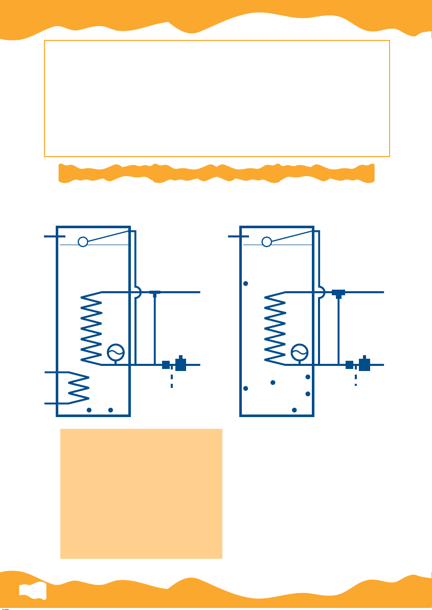
MAINSFLOW CASED CONTRACTOR UNIT
INDIRECT DIRECT
A
C
B
D
DOMESTIC
HOT OUT
E
DOMESTIC
JH
A Warning pipe (Installer to fit)
B Ball float (Supplied)
C Primary Coil/ Boiler Tappings
D Blending valve
E Expansion vessel
F Service valve
G 3.0 bar pressure reducing valve
H Drain Point
J Thermostat connection
K Radiator circuit tappings
COLD OUT
F
G
COLD
MAINS
A
C
C
B
D
DOMESTIC
HOT OUT
E
G
F
K
J
K
H
DOMESTIC
COLD OUT
COLD
MAINS
1

INTRODUCTION
The Albion Mainsflow operates on the Thermal Store principle
eliminating the need for cold water storage in the loft and
producing mains pressure hot water to all taps and shower
facilities at high flow rates in accordance with BS6700.
The Mainsflow Thermal Store principle reverses the traditional
operation of the cylinder in the heating system. The store of water
is heated from the boiler, DIRECTLY to the store or INDIRECTLY
via a second coil. The secondary (domestic) water is provided
through a multi-tube heat exchanger, fed from the main.
Mainsflow DIRECT (single coil) must be fitted in open vented mode,
preferably in twin pump configuration (See page 2, diagram 1).
Mainsflow INDIRECT (twin coil) units can be used with sealed
system boilers i.e. a fully sealed heating system, or with more
traditional open vented systems, where flexible siting is required
- the store being static. The Indirect is usually fitted into a Y
plan system. (See page 2, diagram 2).
Mainsflow Indirect can also be used in central boiler schemes
linking several cylinders to a single boiler or buffer store.
Mainsflow Indirect Cased Contractors are corrosion proofed
and guaranteed for five years. The corrosion proofer is supplied
inside the unit as a soluble crystal. It will not degrade and will
dilute in hot water.
For Direct Units or if you re-commission after use, please add
new inhibitor eg. Fernox MBI or MB2 or Sentinel X100. Follow
manufacturers' instructions to maintain guarantees.
2
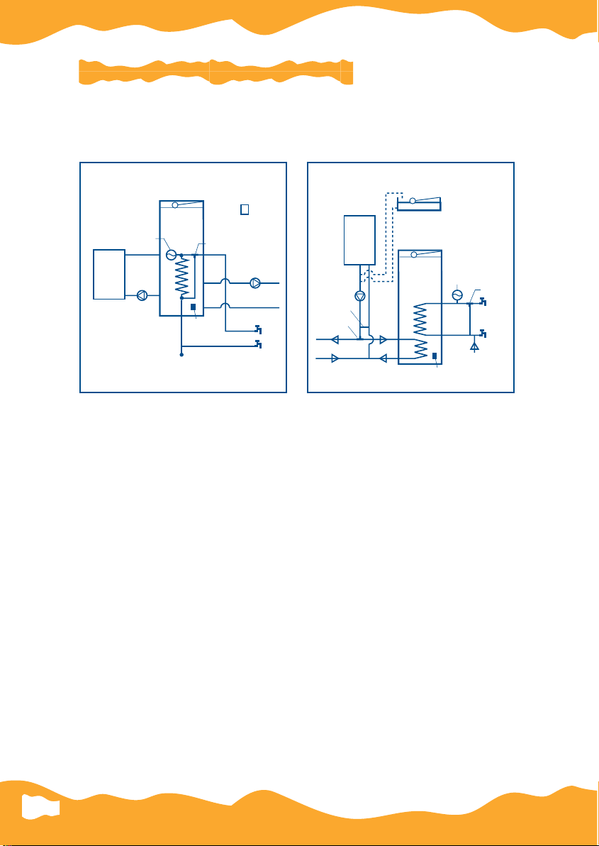
TYPICAL SCHEMATIC LAYOUTS
The Mainsflow units have been engineered to ensure maximum
efficiency from fully pumped systems.
They are not for use in systems with gravity flow and return pipes.
In addition each system is insulated with Albion's unique 100%
CFC free foam and cased in a smart white appliance finish.
DIRECT MAINSFLOW
TWIN PUMP
INDIRECT MAINSFLOW
'Y' PLAN/SEALED SYSTEM
COLD MAINS
PUMP
1
PUMP 2
SPACE
HEATING
HOT
ROOM
THERMOSTAT
COLD
BOILER
STORE
THERMOSTAT
PROBE TYPE
BLENDING
VALVE
EXPANSION
VESSEL
HOT
COLD
BY-PASS
SPACE HEATING
BOILER
*FEED/EXPANSION - OPEN VENTED ONLY
STATIC
STORE
POTABLE
WATER
COLD MAINS
GAS OR OIL
BOILER,
SEALED OR
*OPEN VENTED
PRIMARY
WATER
DIVERTER
VALVE
STORE
THERMOSTAT
PROBE TYPE
BLENDING
VALVE
EXPANSION
VESSEL
Diagram 1
Diagram 2
3

COLD SUPPLY
Mainsflow units are designed to provide hot water directly from the rising
main. Output performance is directly related to the adequacy of the
incoming mains supply. When choosing Mainsflow, installers and
specifiers must take into account flow rates and pressure. The units are
designed to deliver hot water at given flow rates and it is therefore
important to ensure that the mains supply into the property is adequate, ie
a minimum of 2 bar pressure at 20 litres per minute for single bathroom
applications and appropriately for larger installations.
The supplied pressure reducing valve must be fitted. It is recommended
that some cold outlets are connected direct to the mains (kitchen, utility
and outside taps) prior to the pressure reducing valve. The pressure
reducing valve needs to be as far upstream from the cylinder as possible.
The Mainsflow multi-tube heat exchangers are such that scale deposition
will be minimised. However, in areas where concentration of CaCO
3
is
greater than 200mg/l it is recommended that suitable in line scale
eliminators are fitted. If fitted, a by-pass pipe must be installed so that the
system can build up a natural patina for protection prior to using a
proprietary scale eliminator. Consult the manufacturers' guidelines.
INSTALLATION
Albion Mainsflow units should be sited to enable access and removal of all
plumbing connections and components including the unit and overflow
pipes. The units should be positioned on a flat base capable of supporting
them when full up to 300kg (250 litre model).
Where Mainsflow Direct model is used care must be taken to ensure that the
unit is sited to ensure sufficient head for trouble free operation of the system.
They must be sited with the water level at least 500mm above the top of the
highest radiator or highest point in the primary circuit*. Care must always
be taken to allow a clearance of 200mm between the top of all
combination units and the ceiling to allow access to the ball valve for
servicing and adjustment.
The Mainsflow Indirect can be sited anywhere within the property as the
store is static, taking care to discharge pipes effectively.
* Check boiler minimum head requirements.
4

PIPE SIZING
To enable effective distribution of the available supply it is
important in any mains pressure system that pipe sizing is in
accordance with BS6700. As an indication the following pipe
connections are necessary.
Mains supply to the dwelling 22mm (25mm MDPE).
Mains cold supply to the Mainsflow should be run in 22mm
copper.
The hot water draw-off should be 22mm to the bath tap
branch.
The tee-offs to the basins/sinks should be in 10mm, whilst
the tee-offs to the showers should be 15mm.
Primary flow and return pipework should be a minimum of
22mm and sized to 28mm or 35mm according to the boiler
manufacturers' instructions. By-pass pipework must be strictly
in accordance with boiler manufacturers' requirements.
Cold feed to heat exchanger 22mm.
Expansion tank discharge pipework 22mm copper or
22mm plastic solvent weld.
1.)
2.)
MAINSFLOW SIZING
A GUIDE TO SIZING YOUR MAINSFLOW CASED CONTRACTOR
MODEL
MFT140 CON
Specify DIRECT
or INDIRECT
MFT170 CON
Specify DIRECT
or INDIRECT
MFT200 CON
Specify DIRECT
or INDIRECT
MFT250 CON
Specify DIRECT
or INDIRECT
APPLICATION
(TO BS6700)
Single bath and
en-suite shower
2/3 bed property
Two baths
2/3 bed property
Three bath
4 bed property
Three baths and two
en-suite showers
5 bed property
CYLINDER
SIZE
1280 x 560
1500 x 560
1700 x 560
2200 x 560
BOILER
(x 1000 BTU)
40
60
80
100
SIZING
(kW)
12 kW
18 kW
24 kW
30 kW
WEIGHT
(EMPTY)
35kg
37kg
39kg
41kg
WEIGHT
(FULL)
175kg
217kg
249kg
291kg
5

In line with good practice, servicing valves should be fitted to
the system to facilitate maintenance and balancing of the
system. Also all factory made joints should be checked after
installation in case they have loosened during transit. Albion
will not accept responsibility for damage caused where
connections are not checked when commissioning.
Hot and cold taps and mixing valves used in conjunction with
the Mainsflow must be suitable for operating at 10 bar.
Aerated taps are recommended to prevent splashing.
Note: If a water meter is fitted it must be sized appropriately to
prevent flow and pressure restriction. It must be located at least
6 metres upstream from the cylinder. The same distance
applies to non return valves.
6

SERVICING
Units must be serviced annually and the log book at the back of this
guide must be updated. Failure to do this will invalidate the warranty
INSTALLATION CHECKLIST & PROBLEM SOLVING
Store Temperature
Direct units must be maintained at a minimum of 75
o
C. Always
use immersion cylinder thermostats. Indirect (i.e. two coil units)
must be maintained at a minimum of 70
o
C.
Incoming Mains
Minimum 22mm bore, preferred pressures over 2.0 bar. It is
essential to install the 3 bar pressure reducing valve supplied,
to control excess pressure (see page 4).
Hardness
Scale will be a problem where CaCO
3
exceeds 200mg/l. It is
recommended that incoming water is treated appropriately
(see page 4).
Boiler Pump Overrun (Direct models)
See Albion wiring and schematic diagrams (see pages 9 and 10).
System Layout
See Albion diagrams. The water level of the unit must be at the
highest point of the system (see page 4).
Potable Water Controls
These must be fitted to ensure that performance is safe and
complies with by-laws (see page 1 and 3).
Commissioning
Always flush thoroughly on both primary and secondary
circuits. There is no need to flush static stores (indirect models).
Adjust the blending valve if necessary for domestic hot water
preferred temperature.
Inhibitor
Already present in Indirect models, however, add after recommissioning if the unit has been in use. Do not allow any
dilution by draining down after inhibitor is added. Where drain
down occurs new inhibitor must be introduced (see page 2).
7

PROBLEM SOLVING
Poor Flow
140 Litre units are capable of delivering up to 25 litres per
minute 170,210,250 models deliver up to 30 litres per minute.
Check this initially at one outlet (bath). If the flow rate is less
than this, check incoming water pressure flow rates, check all
service valves are open and check blending valves/filters.
Poor hot water temperature
Check that the flow rate is within design parameters. If not,
reduce using flow restrictors.
Check the blending valve is not blocked and is fully open.
Check the store temperature is 75
o
C for Direct unit (70oC for indirect units).
A thorough check of all electrical components to ensure that
they are set and programmed correctly is essential.
Always ensure correct boiler size for the type of system and
dwelling. Smaller boilers will reduce performance, some
modulating boilers will extend recovery times.
Running overflow/warning pipe
Intermittent Adjust the float valve to ensure water level is at
water line point.
Continuous 1) Possible ball valve malfunction - check ball
valve closes fully. If not - replace.
2) Ball valve closes fully. If overflow still runs Check for fractured potable heat exchanger.
Close incoming mains. If overflow stops fault
may be with potable heat exchanger Replace Unit.
THE ALBION HOT-LINE IS MANNED DURING OFFICE
HOURS ON 0121 585 5151.
8

WIRING DIAGRAM
NL1234 C1E 124
L
NE2
3
2
23
LNE
23
EN
L
32
12345678910
FP715
PROGRAMMER
ITC
IMMERSION STAT
RMT 230
ROOM STAT
HEATING PUMP
EN
L
32
BOILER PUMP
BOILER
IMPORTANT – CONNECT NEUTRALS & EARTHS AS NUMERICALLY INDICATED
DIRECT TWIN PUMP FOR BASIC BOILERS AND BOILERS
WITH TIMED PUMP OVERRUN (See Inset)
MAINS
BOILER WITH TIMED PUMP OVERRUN
BOILER
L
N
E
SWITCHED LIVE
PUMP LIVE
JUNCTION BOX
1
2
3
5
9
REMOVE LINK 5 - 9
N.B. FOR THERMAL PUMP OVERRUN
USE MFK 2.
MAINSFLOW DIRECT INTERGRATED THERMAL STORE
9

HEATING SYSTEM
NL1234 CE1124
L
NE2
3
2
23
P
S/L
E
21
EN
L
32EN
L
32
12345678910
HEATING PUMPBOILER PUMP
NL
GBRBLO
3
12
FP715
PROGRAMMER
ITC
IMMERSION STAT
RMT 230
ROOM STAT
HP22 OR 28
ZONE VALVE
BOILER WITH
PUMP OVERRUN
GAS/OIL BOILER WITH REQUIREMENT FOR THERMAL PUMP OVERRUN
DHW
BY PASS
PIPE
GAS/OIL
BOILER
ZONE
VALVE
BOILER
PUMP
P1
HEATING
PUMP
P2
HEATING BY PASS
(IF REQ'D)
HEATING FLOW HEATING RETURN
WIRING DIAGRAM
MAINS
FUSE
3 AMP
IMPORTANT
– CONNECT NEUTRALS & EARTHS AS NUMERICALLY
INDICATED
DIRECT TWIN PUMP THERMAL OVERRUN
MAINSFLOW DIRECT INTERGRATED THERMAL STORE
10

WIRING DIAGRAM
LN431
LNE
L
N
E
EN
L
32
12345678910
HOT WATER ONLY, SINGLE PUMP OPTION
WITHOUT PUMP OVER RUN
C2E1
BL
BR
GO
Br
BI
O
G
2
1
2
PUMP TO 10 ON
BOILER WITH OVER RUN
23
FP715
PROGRAMMER
ITC
IMMERSION STAT
142
RMT 230
ROOM STAT
HP22 OR 28
ZONE VALVE
IMPORTANT –
CONNECT NEUTRALS & EARTHS AS NUMERICALLY INDICATED
2
3
23
MAINS
FUSE
3 AMP
P/L
S/L
E
21
NL
3
CONNECT 10 & 9 FOR BOILERS
WITH PUMP OVER RUN
910
WITH PUMP OVER RUN
MAINSFLOW INDIRECT HOT WATER ONLY STORE
11

For servicing of ball valve and float, checking water levels, inhibitor
concentration or warning pipe connection
Access to the inside of the cased Mainsflow is via the top of the unit. The
cased lid is a friction fit and lifts off. This lid is insulated. Removal of the
lid exposes a standard aluminium combination tank top. This again is a
friction fit and will pull off. REMOVE CAREFULLY.
The stored water will be HOT (80ºc). There is no cold tank. Water droplets
of condensation may have formed on the underside of the combination
tank top, for safety reasons you may prefer to carry out this procedure
when tank is cold.
On completion of remedial work or service maintenance ensure the cold
water level does not exceed the height of the swage line.
Refit the aluminum top ensuring the overhanging edge is a tight fit to the
copper tank.
Refit the case lid ensuring insulation is securely in place.
ACCESS TO THE STORE
APPROVED MAINSFLOW SPARES
Thermostatic Blending Valve
Pressure Reducing Valve
Single Non Adjustable Thermostat
Expansion Vessel / Stock Arrestor
TBV1
PRV 3.0 bar
NAT 1
SA1
DESCRIPTION CODE
12

A USERS GUIDE TO THERMAL STORE
This leaflet describes thermal store hot water and central heating system installed in
these premises in simple terms.
Advice is given on the use of and adjustment of the various controls to get the best out
of the system.
Albion Mainsflow Systems offer the householder efficiency and high performance. All
services are linked to the mains cold water service. This eliminates bulk cold water
storage in the loft and generally improves hot water delivery at taps and shower outlets.
Please ensure that you follow the start up procedure at all times when the system has
been switched off or when an apparent fault occurs. This should be done before calling
out a plumber or service engineer.
THE SYSTEM
The system is designated a ‘thermal store’. The water in this system is controlled
by an immersion cylinder thermostat installed in the store. For the production of
hot water and central heating it is recommended that the store has to be on a 24
hour programme. However, the unit can be timed if pump or boiler noise is a
problem to come on in the morning and go off in the evening. This should be a
continuous period.
HOT WATER
When hot water is required, water from the cold mains is passed through a high
efficiency coil located in the store. The water in the store is at radiator temperature, too
hot to pass straight to the taps, so a blending valve is fitted to introduce cold water.
The resultant temperature at the taps being approximately 55
o
C
To fill a normal bath to an average depth takes approximately 4 minutes, hot water is
available during boiler operation.
CENTRAL HEATING
When central heating is required from a Direct Integrated System the room thermostat
switches on the heating pump. When rooms have reached the full design temperature
the thermostat will turn off the heating pump. The boiler pump will continue until the
store temperature is replenished. With a Indirect Hot Water Store the heating flow to
the radiators is provided directly from the boiler again controlled by a room thermostat.
TO START
If the system is new and the boiler has not been ‘on’ then it is necessary to pre-heat
the store (cylinder). This is done by turning the boiler ‘on’. The thermostat on the boiler
must be set at maximum at all time for the system to function correctly. Instruction for
lighting the boiler will be found behind the boiler panel. Set the heating clock to ‘off’
and leave for approximately 1
1
/4 hours, after this time set the clock to operate ‘on’
and ‘off’ to your requirements.
If the boiler is turned off for any reason, say holidays etc., and the store cools off, then
the above must be carried out before satisfactory operation will be achieved. It may be
necessary to operate the reset button on the programmer to reset unit.
USER GUIDE
13

OPERATION
To ensure high efficiency and rapid response to heating demands and to give 24 hour
hot water the highly insulated store is maintained at full temperature at all times,
consequently the boiler and store pump will operate at times when the central heating
clock is ‘off’. This is a normal function of the system and is one of the reasons that it is
so efficient.
The unit can be timed if pump or boiler noise is a problem, with one "off" period during
the night to suit demand.
BLENDER
As previously mentioned, this controls the temperature of the hot water at the taps to a
maximum of approximately 55
o
C and is factory set but if required the installer can
adjust this to give small variations in temperature either hotter or cooler.
STORE THERMOSTAT
This is factory set with fine adjustments being made by the installer. No further
adjustment should be made by anyone other than a qualified installer, otherwise
efficiency and performance will be affected.
THE ROOM THERMOSTAT
If the room thermostat is provided, start by setting it at the temperature quoted for the
room in which it is fitted and then adjust it to whatever setting you find most
comfortable. But remember if you overheat your house by 1
o
C, fuel costs will rise by 3
to 5 per cent. So set the thermostat just high enough for you to be comfortable.
Rather than opening windows or turning on extractor fans to control room
temperatures, use the thermostat. Where you need extra ventilation, as in kitchens and
bathrooms, keep it to the minimum necessary. And remember to shut that door! A
room thermostat can do its job much more effectively behind closed doors.
THE PROGRAMMER
The time clock enables your central heating system to be switched on and off automatically
usually twice every 24 hours, at a time selected by you to suit your daily routine.
Where the house is empty during the daytime, a sensible arrangement is for the heating to
come on about an hour before you get up, go off half an hour before you go out, come on
again and hour before you come home and go off again half an hour before you go to bed.
Please refer to the individual programmer instruction applicable to your unit.
Also note that if the appliance has been switched off for some days it maybe
necessary to use the reset button to start the programmer.
14

FROST THERMOSTAT
If the boiler is fitted in a semi-exposed situation, such as a garage or outbuilding, a
frost thermostat may be fitted. This overrides the clock should the temperature
approach freezing. It will be set by the installer and you should not alter the setting.
VENTILATION
Under no circumstances should any ventilation grilles provided for the boiler be
blocked.
AIR RELEASE VALVES
If only the bottom of the radiator gets hot, trapped air is usually the cause and this
can easily be released. Having first turned the time clock ‘off’, open the air release
valve which is at the top of the radiator. Open the valve half a turn only until water
appears, then close it. A piece of cloth is useful to catch the water.
IMPORTANT
Radiators should not be covered by curtains or furniture. Heat trapped behind closed
curtains will mostly be lost through the window. Nor should radiators be boxed in.
They may be painted with any oil-based gloss paint but not with metallic paint which
will reduce their efficiency, or emulsion paint which is water-based and may cause
rusting.
Before calling out plumbers or your normal contact please ensure that
the full start up procedure has been followed.
15

TM
is supported by
WATERHEATER
MANUFACTURERS
ASSOCIATION
Thermal Store
Installation,
Commissioning and
Service Record
Log Book
(To be retained by customer).
INSTALLER DETAILS
APPLIANCE DETAILS
COMMISSIONING RECORDS
SERVICE INTERVAL RECORD
IMPORTANT
FAILURE TO INSTALL & COMMISSION THIS APPLIANCE TO THE
MANUFACTURER’S INSTRUCTIONS MAY INVALIDATE THE WARRANTY
This note does not affect your statutory rights.

INSTALLER & COMMISSIONING ENGINEER DETAILS
CUSTOMER DETAILS
NAME
ADDRESS
TEL No.
INSTALLER DETAILS
NAME
ADDRESS
TEL No.
DATE
REGISTRATION DETAILS
REG No.
ID SERIAL No. etc.
COMMISSIONING ENGINEER
DETAILS
NAME
ADDRESS
SERVICE REQUIREMENTS
1
Check valve operation of pressure
reducing valve should be 3.0 bar static
- only adjust if necessary
2
Check flow rates are satisfactory - clean
filter in pressure reducing valve only if
required. Do not exceed stated flow
rates.
3
Check charge in expansion vessel.
Should be 3.0 bar - inflate as required
after decommissioning the system.
4
Check operation of ball valve float,
adjust or replace as required.
5
Check store inhibitor strength;
If Fernox MBI = 4%
If Sentinal x 100 = 1%
If Albion static store inhibitor = 1%
TEL No.
DATE
REGISTRATION DETAILS
REG No.
ID SERIAL No. etc.
Should further assistance or clarification be required contact Albion Advice
on 0121 585 5151
Failure to carry out annual
service/maintenance requirements and
log proof in service/maintenance
records may invalidate warranty.
APPLIANCE DETAILS
MANUFACTURER MODEL
CAPACITY LITRES SERIAL NO.
GENERAL INSTALLATION
HAS A CHECK BEEN DONE FOR JOINT TIGHTNESS AND LEAKS? YES NO
HAS A CHECK BEEN DONE FOR ELECTRICAL SAFETY? YES NO

SERVICE INTERVAL RECORD
It is recommended that your heating system is serviced regularly and that your service engineer completes the
appropriate Service Interval Record below.
SERVICE PROVIDER
Before completing the appropriate Service Interval Record below, please ensure you have carried out the service
as described in the manufacturer’s instructions and in compliance with all the relevant codes of practice.
SERVICE 1 DATE
ENGINEER NAME
COMPANY NAME
TEL No.
ID SERIAL No.
COMMENTS
SIGNATURE
SERVICE 3 DATE
ENGINEER NAME
COMPANY NAME
TEL No.
ID SERIAL No.
COMMENTS
SIGNATURE
SERVICE 5 DATE
ENGINEER NAME
COMPANY NAME
TEL No.
ID SERIAL No.
COMMENTS
SERVICE 2 DATE
ENGINEER NAME
COMPANY NAME
TEL No.
ID SERIAL No.
COMMENTS
SIGNATURE
SERVICE 4 DATE
ENGINEER NAME
COMPANY NAME
TEL No.
ID SERIAL No.
COMMENTS
SIGNATURE
SERVICE 6 DATE
ENGINEER NAME
COMPANY NAME
TEL No.
ID SERIAL No.
COMMENTS
SIGNATURE
SERVICE 7 DATE
ENGINEER NAME
COMPANY NAME
TEL No.
ID SERIAL No.
COMMENTS
SIGNATURE
WHEN ALL OF THE ABOVE SERVICE HAVE BEEN COMPLETED, PLEASE CONTACT YOUR SERVICE ENGINEER
FOR AN ADDITIONAL SERVICE INTERVAL RECORD SHEET.
SIGNATURE
SERVICE 8 DATE
ENGINEER NAME
COMPANY NAME
TEL No.
ID SERIAL No.
COMMENTS
SIGNATURE

COMMISSIONING PROCEDURE INFORMATION
BOILER PRIMARY SETTINGS
IS THE PRIMARY SEALED OR OPEN VENTED SYSTEM? Sealed Open
IF SEALED THEN WHAT IS THE SYSTEM PRESSURE? Hot Cold BAR
IF SEALED THEN WHAT IS THE CHARGE PRESSURE OF EXPANSION VESSEL? BAR
WHAT IS THE AVAILABLE BOILER FLOW TEMPERATURE?
WHAT IS THE BOILER RETURN TEMPERATURE WHEN CYLINDER/STORE IS SATISFIED?
ALL MAINS PRESSURE SYSTEMS
WHAT IS INCOMING COLD WATER PRESSURE? BAR
HAS A WATER TREATMENT DEVICE BEEN FITTED? YES NO
IF YES TO ABOVE THEN WHAT TYPE?
THERMAL STORE SYSTEMS ONLY
IS THE STORE TREATED WITH INHIBITOR?
(NOTE - FOR INDIRECT THERMAL STORES THE STORE MUST BE TREATED IN ADDITION
TO THE PRIMARY SYSTEM)
IS A 3 BAR PRESSURE REDUCING VALVE FITTED?
IS THE EXPANSION VESSEL FULLY CHARGED AT 3 BAR?
IS THE OVERFLOW/WARNING PIPE INSTALLED IN LINE WITH BEST
PRACTICE?
IS THE BLENDING VALVE SET AT 55
IS THE DHW FLOW CONTROLLED TO THE APPROPRIATE RATE?
IF CYLINDER IS IT VENTED CORRECTLY?
IS THE CYLINDER STAT SET TO 70
o
C TO 75oC?
(INTEGRAL IN CASED CONTRACTOR)
o
C?
CONCENTRATION
YES NO
TYPE
YES NO
YES NO
YES NO
YES NO
YES NO
YES NO
YES NO
o
o
C
C
ALL PRODUCTS
HAS THE SYSTEM BEEN EXPLAINED TO THE HOUSEHOLDER? YES NO
HAS THE SYSTEMS LITERATURE BEEN LEFT WITH THE HOUSEHOLDER? YES NO
ENGINEERS SIGNATURE CUSTOMERS SIGNATURE
 Loading...