

Page 1
USER MANUAL
High Definition Multimedia
Pure Flat Monitor
DM-5952KF / DM-6952KF
A73110002790
Page 2

TABLE OF CONTENTS
1. FCC STATEMENT................................................................................. 1
2. SAFETY INSTRUCTIONS..................................................................... 2
3. README FIRST .................................................................................... 4
4. WITHOUT VISION CONVERTER ......................................................... 6
5. WITH【CT-1871】VISION CONVERTER ............................................ 7
6. WITH【CT-1890∕CT-1892】VISION CONVERTER
7. INSTALLATION ..................................................................................... 9
8. USING THE MONITOR ....................................................................... 12
9. Using the Remote Control ................................................................... 14
10. ACCESSING THE MAIN MENU........................................................ 18
11. ENERGY SAVING............................................................................. 22
12. REAR CONNECTORS【CT-1871】................................................. 23
13. REAR CONNECTORS【CT-1890∕CT-1892】............................... 24
14. SIMPLE TROUBLE SHOOTING TIPS .............................................. 25
15. Model:DM-6952KF SPECIFICATIONS........................................... 26
16. Model:DM-5952KF SPECIFICATIONS........................................... 27
17. VGA CONNECTOR ASSIGNMENT.................................................. 28
18. RS-232 CONNECTOR ASSIGNMENT ............................................. 29
19. FACTORY PRESET AND COMPATIBLE MODE ............................. 30
20. IR REMOTE CONTROLLER CODE.................................................. 31
21. DM RS232 QUICK INSTALLATION .................................................. 32
.................................... 8
1. FCC STATEMENT
This equipment has been tested and found to comply within regulations for a
Class B digital device, pursuant to Part 15 of the FCC rules. These regulations
are designed to provide protection against harmful interference in a residential
installation. This equipment can generate, use and radiate radio frequency
energy, and if not installed and∕or used in accordance with the instructions
provided, may cause harmful interference to radio communications. However,
there is no guarantee that interference will not occur in a particular installation.
If this equipment does cause harmful interference to radio or television
reception, which can be determined by turning the equipment off and on, the
user is encouraged to try to correct the interference by one or more of the
following measures:
• Reorient or relocate the receiving antenna.
• Increase the separation between the equipment and receiver. Connect the
equipment into an outlet on a circuit different from that to which the receiver
is connected.
• Consult the dealer or an experienced radio∕TV technician for assistance.
Warning:
Only use shielded cable to connect I/O devices to this equipment.
Changes or modifications not expressly approved by the party responsible for
compliance could void your authority to operate this equipment.
0
1
Page 3

2. SAFETY INSTRUCTIONS
1. Read all of these instructions.
2. Save these instructions for later use.
3. Follow all warnings and instructions marked on the product.
4. Unplug this product from the wall outlet before cleaning. Do not use liquid
cleaners or aerosol cleaners. Use a damp cloth for cleaning.
5. Do not use this product near water.
6. Do not place this product on an unsuitable cart, stand or table; the product
may fall causing damage or injury.
7. Slots and openings in the cabinet and the back or bottom are provided for
ventilation. To ensure reliable operation of the product and to protect it
from overheating, these openings must not be blocked or covered.
Placing the product on a bed, sofa, rug, or other similar surface should
never block the openings. This product should never be placed near or
over a radiator or heat register. This product should not be placed in a
built-in installation unless proper ventilation is provided.
8. This product should be operated from the type of power source indicated
on the marking label. If you are not sure what type of power available,
consult your dealer or local Power Company.
9. This equipment is to be electrically grounded. This product is equipped
with a three-wire plug with a third (grounding) pin. This plug will only fit
into a grounded AC outlet. This is a safety feature. If you are unable to
insert the plug into the outlet, contact a licensed electrician to replace the
outlet with a properly grounded outlet. Do not defeat the purpose of the
grounding plug!
10. Do not allow anything to rest on the power cord. Do not locate this
product where persons will walk on the cord.
11. If an extension cord is used with this product, make sure that the total of
the ampere ratings on the products plugged into the extension cord does
not exceed the extension cord ampere rating. Make sure that the total of
all products plugged into the wall outlet does not exceed 15 amperes.
12. Never push objects of any kind into this product through cabinet slots as
they may touch dangerous voltage points or short out parts that could
result in a frisk of fire or electric shock. Never spill liquid of any kind on
the product.
13. Do not attempt to service this product yourself, as opening or removing
covers may expose you to dangerous voltage points or other risks. Refer
all servicing to qualified service personnel.
14. Unplug this product from the wall outlet and refer servicing to qualified
service personnel under the following conditions:
a. When the power cord or plug is damaged or frayed.
b. If liquid has been spilled into the product.
c. If the product has been exposed to rain or water.
d. If the product does not operate normally when the operating
instructions are followed. Adjust only those controls that are covered
by the operating instructions since improper adjustment of other
controls may result in damage and will often require extensive work by
a qualified technician to restore the product to normal operation.
e. If the product has been dropped or the cabinet has been damaged.
f. If the product exhibits a distinct change in performance, indicating a
need for service.
2
3
Page 4
3. README FIRST
These easy start-up tips will guide you in making the connections to get you
up and running.
USING WITH A DESKTOP PC OR LAPTOP
1. Prior to connecting the monitor, if you have a desktop monitor connected to
your PC, please insure that the video card refresh rate is set within the
Monitors frequency range by going to:
Start…Settings…Control
Panel…Display…Settings…Advanced…Adapter.
Set the Adapter refresh rate to 60Hz or “Adapter Default”. This applies to
the three supported resolutions of 640×480, 800×600 and 1024×768.
Otherwise, the monitor will not display and the unit will go into
standby mode
2. Plug the AC power cord from the power source (outlet) to the AC input of
the monitor.
3. Connect the VGA cable provided from your computer’s VGA output to the
input on the monitor.
VGA 1 VGA 1 input port located in the rear of the monitor.
VGA 2 VGA 2 input port located in the front of the monitor.
Note:Be sure the PC is powered on before the monitor.
Press the VGA1∕VGA2 select button, located next to the front VGA
connector and on the Remote Control until the computer image is
displayed.
(Yellow-orange LED).
SIMULTANEOUS VIEWING OF THE MONITOR AND STANDARD PC
MONITORS
Connect the VGA cable from the PC’s VGA output to the VGA input. Then
plug the desktop monitor’s VGA cable to the monitor VGA output.
USING WITH A LAPTOP
If you are using Notebook;Press Fn. + F5 (or Fn. + F3) to output the display
to CRT only (CRT output combination key might be different on every
notebook), or press combination key again to show on both CRT and LCD
display.
USING WITH A MAC
1. Plug the AC power cord from the power source (outlet) to the AC input of
our monitor.
2. Connect the MAC adapter to the MAC monitor output (if required the MAC
model). Refer to the adapter user’s manual for the proper dipswitch settings.
The optimum setting for the monitor is a resolution setting of 800ɰ600 and
a refresh rate of 60Hz. Make sure the display settings of the MAC is set to
800ɰ600 at 60Hz as well.
Note:You need a MAC adapter when using the monitor with older MAC
Computers. The MAC adapter converts the output to VGA HD-15 pin
out. This adapter is available at an additional cost.
3. Connect the VGA cable from the monitor to the MAC adapter.
4
5
Page 5
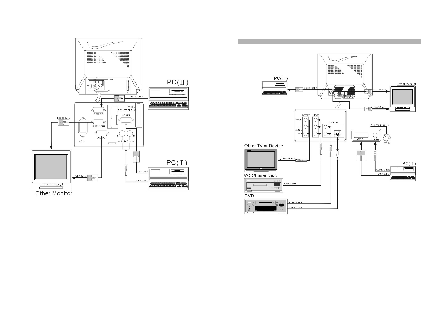
4. WITHOUT VISION CONVERTER
5. WITH【CT-1871
Note:Only for Rev.K-1 or higher.
】
VISION CONVERTER
FIGURE 1:DM-XX52KF W/O VISION CONVERTER CONNECTION
6
FIGURE 2:DM-XX52KF CONNECT WITH CT-1871 VISION CONVERTER
7
Page 6
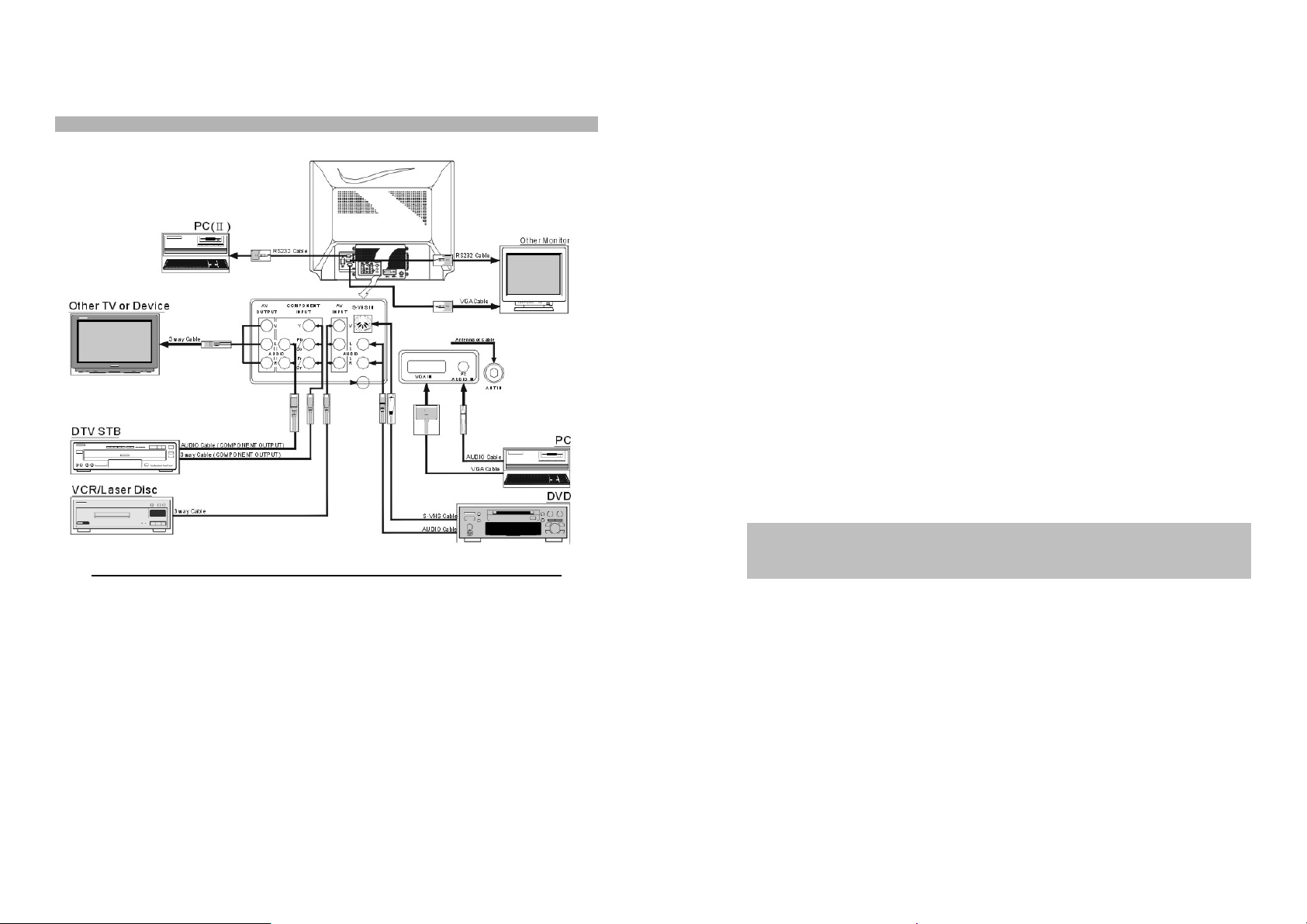
6. WITH【CT-1890∕CT-1892】VISION CONVERTER
Note:Only for Rev.K-1 or higher.
FIGURE 3:DM-XX52KF CONNECT WITH CT-1890/CT-1892 VISION CONVERTER
7. INSTALLATION
Precautions
Monitor shall be placed at least 6 inches away from the obstructer.
a. Monitor will work well when connect with computer and any high
definition receiver. With a high definition resolution, Monitor is designed
without video converter with it. To work as a TV or using with VCR and
DVD, you must to connect with a video converter.
b. The following descriptions are based on Monitor connected with video
【
converter ready.
Television
1. Install cable from antenna or cable TV to the “F” connector labeled “ANT
IN”.
2. Press the Power ON, and the Red LED Indicator should be lit on the
monitor, and the monitor is on STAND BY mode.
3. Press the POWER button on the Remote-controller; the Red indicator
should turn into green.
4. Press TV∕PC∕AV button or press TV button on Remote-Controller
until the monitor displays MAIN NTSC TV.
5. To switch to TV∕CATV mode, select TV if you are using an antenna, or
select CATV if you have a cable service.
6.
Press AUTO button with your remote control, and Monitor will now
preset all active channels into memory.
7. Selecting a channel.
a.
Press CH
panel
.
b. Press the numeric key to select a desired channel.
8. Press VOL +∕VOL - to adjust the volume on remote control or the front
panel.
Video Recorder (VCR)
1. To connect the signal by F Connector, following the instruction to setup
your Television.
2. If using the Video (Composite) from the VCR, connect the Video input
with Left, and Right Speaker.
3. Start the VCR.
4. Using the Remote control press TV∕PC ∕ AV button until or press
VIDEO button until VIDEO appears on the screen.
5. If using the S-Video output of the VCR. Connect an S cable from the
VCR to Monitor.
See Figure 2 ~ 3】
▲∕▼
to select channels on Remote control or on the front
8
9
Page 7

6. Connect the Left and the Right audio channel to monitor.
7. Start the VCR.
8. Press the TV∕PC∕AV button or press S-VHS button by remote control
until S-VHS appears on the screen.
DVD player
1. Connect the Video input with Left and Right speaker on DVD.
2. Start the DVD player.
3. Press the TV ∕ PC ∕ AV button or press VIDEO button by Remote
control until VIDEO appears on the screen.
4. If using the S-Video output of the DVD, connect an S cable from the
DVD with monitor.
5. Connect the Left with the Right audio channel.
6. Start the DVD player.
7. Press TV∕PC∕AV button or S-VHS button until appears on the screen.
8. If using the component output of the DVD, connect a component video
cable from the DVD with monitor.
9. Connect the left with the right audio channel.
10. Start the DVD player.
11. Using the Remote Control, press the TV ∕ PC ∕ AV button or the
Component button until Y, Cb, Cr∕Y, Pb, Pr appears on the screen.
Computer
1. Connect the computer with the monitor by using VGA1 that located on
the rear panel, or VGA2 that located on the front panel.
2. Connect the Audio to the appropriate audio connector next to the VGA
connector.
3. Press the TV∕PC∕AV button or press VGA1∕VGA2 button until
VGA1 ∕VGA2 appears on the screen.
4. If monitor has no display, check your video card on the appendix B.
5. If there is no display on the screen, verify if the proper input VGA1∕
VGA2 has been manually selected.
High Definition Receiver
1. If your HD receiver has a VGA connector, it can be used to input monitor.
2. Connect a Receiver to the monitor using the VGA1 located on the rear
panel or VGA2 located on the front panel.
3. Connect the Audio to appropriate audio connectors next to the VGA
connector.
4. Using the Remote control, press the TV∕PC∕AV button or press VGA1
∕VGA2 button until VGA1∕VGA2 appears on the screen.
5. Press MENU, then press the right arrow key on the picture to adjust the
geometry controls for a good picture.
6. If using the component output of the DVD, connect an component video
cable from the DVD with monitor.
7. Connect the left with the right audio channel.
8. Start the DVD player.
9. Using the Remote Control, press the TV ∕ PC ∕ AV button or the
Component button until Y,Cb,Cr∕Y,Pb,Pr appears on the screen.
10
11
Page 8

A
8. USING THE MONITOR
This section describes how to use and make adjustments to the monitor. It
also provides a reference to the control panel and the remote control.
Using the Control Panel
Using control panel to control the monitor instead of the remote control.
However, some other functions are not set on control panel. There are 7 panel
keys, and following lists the function buttons on the control panel:
DM-XX52KF VGA2 IN & PANEL KEYS
Indicators
a. Power LED shows power on∕off, and power saving status.
b. Stereo LED is lit when the TV programs being received.
c. SAP LED is lit when the program is broadcast in Sub-audio.(2
program)
Power LED Stereo LED SAP LED
Normal on Green Stereo On (Red) Main Audio Off
Stand by Amber Mono Off Sub Audio On (Yellow)
Suspend∕Active off
Power off Red
TABLE 1:INDICATOR OPERATION DESCRIPTION
Red
nd
audio
POWER
DEGAUSS
(PC⁄TV⁄AV)
MENU
SEL+∕CH+
SEL-∕CH-
Note:
When you are adjusting a function under the magnitude bar, you may also
adjust other items in the same group by pressing the up∕down keys. Don’t
go back to the previous menu by way of the MENU key.
VOL
+∕-
TV∕CATV
(VGA 1∕VGA2)
Note:Auto-switch function:On VGA mode, upon POWER-ON, and at
POWER-ON only, the monitor will automatically switch to the other port
when NO signal appears after 8 seconds. On other words, VGA1 will
switch to VGA2, and vice versa. But if ports have NO input, this monitor
will switch back to the original default port.
(Toggle) Starts or stops the monitor function.
This is a dual function key:
a. Switch the input source through TV∕PC∕VIDEO∕S-
Video ∕COMPONENT∕TV while connect with a vision
converter.
b. Press this key to execute degaussing while in normal
status. Each degauss is lasting for 4 seconds, and
waiting for 5 minutes to re-do degauss.
(Toggle) Enables/Disables the on-screen display menu, or
return to the upper level menu in the menu mode.
This is a dual function key:
+∕-
a. Press SEL
b. Press CH+∕- to adjust the channel.
This is a dual function key:
a. Press
b. Press
Select TV or CATV pair as inputs. While in the TV/C
mode; the VGA 1∕VGA 2 key serves as TV∕CATV key.
VOL
in menu function.
VOL
in menu mode.
to serve as menu item selection.
+ ∕-to control volume in any mode, except
(
optional)
+ ∕-to control the selection function while
TV
12
13
Page 9

A
9. Using the Remote Control
Using remote control instead of the control panel is convenient to operate the
monitor. Some of the keys must to work by connect with MATE, and these are
DISP, SLEEP, MTS, JUMP, ADD ∕ ERASE, AUTO, TV, VIDEO, S-VHS,
COMPONENT, TV∕PC∕AV, TV∕CATA, PIC-STD, PIC∕PAGE, PIC-SEL,
SYSTEM, FINE TUNING, CH-LOCK, FIELD, LANG, CAP∕TXT, CCD.
REMOTE CONTROL
Note:
The mute function will automatically unlock if any adjusts are made related to
audio (i.e., volume, bass, etc.)
Following lists the function keys on the remote control:
POWER
POWER ON∕OFF
DISP
SLEEP
MTS
MUTE
JUMP
ADD∕ERASE Allows the user to Add∕Erase channels manually.
AUTO
MENU
MIC∕SEL+
MIC
∕
SEL-
∕
VOL+
-
Starts or stops the monitor function.
To Start or stop the multiple monitors function in the
meanwhile. In general, this function is used well with
multiple monitors’ control.
Display the current mode on the present status.
To set the sleep timer, each press will increase the sleep
timer in 10-minute intervals up to 120 minutes (then back to
00). When the sleep count reaches the last 5 minutes, the
screen will show up every minute for 3 seconds. During the
last minute, and it will display every 10 seconds.
Multi-Sound selection.
Cuts audio and turns audio back on.
Returns to the previous channel.
utomatically scan all the channels by signal responds, and
to set them on the preset mode.
Enable/Disables the On-Screen Display Menu.
This is a dual function key:
a. Press SEL +∕- to serve as menu item selection.
b. MIC for R mode.
This is a dual function key:
a. Press VOL +∕- to control volume in any mode.
(
optional)
b. Press VOL+∕- to control the selection function while in
menu mode.
14
15
Page 10

A
Note:Volume control function will effect while connect with Vision Converter.
SYSTEM
Changes the video system on TV, Video, and S-VHS.
System types are PAL, PAL-M, PAN-N, and SECAM.
SET
Through DM RS232 V0.9
interface)
to remote control the device. To identify the monitor, you
(Serial Transmission Communication
must to set an ID number (ID=1~99) to each of the monitor under
ID
TV
VIDEO
S-VHS
Component
DM RS232 V0.9 Control page.
To set the ID number to control the monitor from the other.
Select TV source.
Select VIDEO source.
Select S-VHS source.
Select a Compound signal source:
Y,Pb,Pr —For High definition component inputs.(CT-1890).
Y,Cb,Cr—For Conventional component inputs.( CT-1890∕
CT-1892).
VGA 1
VGA 2
Select VGA 1 source.
Select VGA 2 source.
TV∕PC∕AV Select TV∕PC∕VIDEO∕S-Video∕COMPONENT∕switch
source.
FINE TUNING
CH-LOCK
FIELD
LANG
CAP∕TXT
CCD
Allows for fine-tuning of channels.
For Parental Control.
FIELD 1 or FIELD 2 toggle. (Useable only when CCD is
on).
Language Selection (1 or 2).
Accessible only when CCD is on.
Caption control.
TV∕CATV Select TV∕CATV source.
+∕CH-
CH
PIC-STD
PIC∕PAGE
PIC-SEL
Steps through the channels.
Factory preset.
Control and select items PIC-SEL button.
▲▼
User video adjustment screens.
16
17
Page 11

10. ACCESSING THE MAIN MENU
Access the OSD Menu by control panel on the monitor or the remote control
to make the operation.
Screen-1 Screen-2 Screen-3
Following lists the function keys on the OSD:
Note:
Press the Menu button on the control panel or the remote
control to display the main menu.
Press the SEL +/- buttons on the control panel or remote control
to scroll through the menu.
Press the VOL +/-buttons on the control panel or the remote
control to adjust the setting values.
Press Sub-menu to return to upper level while in any sub-menu.
To exit the menu mode, press the menu button while in the toplevel menu.
MAIN MENU
Screen-4 Screen-5 Screen-6
Screen-7 Screen-8 Screen-9
OSD FUNCTION CHART
Picture Menu
Note:
a. Recall will replace current settings by the factory-preset values. You can
only recall factory settings when the PC mode is in one of the 14 predefined
modes. See Table 3 appendix B for preset modes. Color recall is used to
call back the factory setting of R.G.B.
b. Above parameters is for PC mode only, and can’t be reached in TV ∕AV
mode. In TV∕AV mode, you can adjust the TV parameters by remote
control.
Color Menu
Audio Menu
Fine tunes the Picture image quality manually:
CONTRAST 、 BRIGHTNESS 、 H ∕ V SIZE 、 H ∕ V
POSITION、PINCUSHION、TRAPEZOID、TOP-CORNER、
BOTTOM-CORNER 、PIN-BALANCE、PARALLELORGAM、
ROTATION and RECALL.
Select the color temperature to make colors more pure
and vivid. Select user item to adjust the color intensity
by VOL+∕-key.
Fine tune the audio functions manually:
Bass、Treble、Balance、Volume.
18
19
Page 12

Special Menu
y
A
A
Fine tunes and sets the special functions manuall
:
ID-NUMBER ( 1~99 )、INSTANT-ON 、 DEGAUSS 、
AUTO-SAVING 、 AUTO DEGAUSS 、 AUTO SHIFT 、
OSD BACKGROUND、OSD CONTRAST、AND OSD H
∕V-POSITION、MOIRE、 KEY LOCK、PASSWORD.
g. Moiré For some modes, it is better to switch the moiré off to get
better video performance, and this option is provided
when Moiré is ON, adjust MOIRE pops out, and adjust
moiré by using +∕-key. In TV∕
V mode, moiré can’t
be adjusted.
a. ID Number Through DM RS232 V0.9 (Serial Transmission
Communication interface) to remote control the
device. To identify the monitor, you must to set an ID
number (ID=1~99) to each of the monitor under DM
RS232 V0.9 Control page.
1. Select the ID number (1~99) by tab.
2. After you set the ID, choose high/light to identify the
monitor with has been set with a valid number. The
monitor will correspond with the current status, and this
could control the OSD function directly.
b. Instant-On
Enable∕Disable the INSTANT-ON. Set the INSTANT–
ON YES, the Monitor will start up immediately while the
Power switch on, and the green LED is lit on. The monitor
will stay in the saving mode till the power be turn-on again
while the INSTANT-ON is switch off, and the red LED is lit
on.
c. Auto Saving The power will shut down automatically and be in the
power-saving status while the Auto Saving switch on.
e. Degauss
Enable∕Disable the AUTO DEGAUSS.
The AUTO DEGAUSS will be executed automatically by
every 24 hours since switch on the function.
h. Key Lock
Enable∕Disable the front panel function operation.
i. Password To release the disable front panel function operation by
set the password.
j. OSD
Background
Switch the OSD background ON or OFF to adapt to
different software background of the PC.
f. Auto Shift
ctive AUTO SHIFT to protect the screen from result in
the image-remain. The picture will be auto-shift once
every 6 hours.
20
21
Page 13

11. ENERGY SAVING
All monitor is Energy Star compliant. It contains special hardware that
provides energy saving, automatic Stand By and Shut OFF features. After a
period of time, the monitor will be in power-saving status automatically until
the mouse or use the keyboard.
Automatic Stand By and Shut OFF are set through a software program
on your computer.
Model MAX. Power on Stand by Suspend Off
DM-6952KF 200W 90W 5W 5W
DM-5952KF 210W 90W 5W 5W
POWER CONSUMPTION STATUS
12. REAR CONNECTORS【CT-1871
1. AC in
2. VGA out
3. Video out
4. Audio out (Left)
5. Audio out (Right)
6. Video in
7. Audio in (Left)
8. Audio in (Right)
9. Audio in (Left)
10. Audio in (Right)
11. S-Video in
12. VGA1 in
13. Audio in
14. Antenna in
15. RS-232 In
16. RS-232 Out
Connect the power source to the monitor.
Video signal connector Output the signal to another
monitor.
Composite Video output to another device.
Left speaker signal to another device.
Right speaker signal to another device.
Composite from a VCR or DVD player
Composite, from a VCR or DVD player.
Composite, from a VCR or DVD player.
For S-Video signal.
For S-Video signal.
From a VCR or DVD player.
From Computer or HDTV receiver.
From Computer.
From antenna or cable TV.
Connect the external source from PC to the monitor.
Connect the external source From monitor to other
external source
CT-1871 REAR CONNECTORS
.
】
22
23
Page 14

13. REAR CONNECTORS【CT-1890∕CT-1892
1. AC in
2. VGA out
3. Video out
4. Audio out (Left)
5. Audio out (Right)
6. Video in
7. Audio in (Left)
8. Audio in (Right)
9. Audio in (Left)
10. Audio in (Right)
11. S-Video in
12. VGA1 in
13. Audio in
14. Antenna in
15. Y in
16. Pb∕Cb in
17. Pr∕Cr in
18. Audio in (Left)
19. Audio in (Right)
20. RS-232 In
21. RS-232 Out
Connect the power source to the monitor.
Video signal connector Output the signal to another
monitor.
Composite Video output to another device.
Left speaker signal to another device.
Right speaker signal to another device.
Composite from a VCR or DVD player
Composite, from a VCR or DVD player.
Composite, from a VCR or DVD player.
For S-Video signal.
For S-Video signal.
From a VCR or DVD player.
From Computer or HDTV receiver.
From Computer.
From antenna or cable TV.
Component Video Input, from a DVD player or HDTV
receiver.
Component Video Input from a DVD player or HDTV
receiver.
Component Video Input from a DVD player or HDTV
receiver.
For Component Video Signal.
For Component Video Signal.
Connect the external source from PC to the monitor.
Connect the external source From monitor to other
external source.
CT-1890/CT-1892 REAR CONNECTORS
】
14. SIMPLE TROUBLE SHOOTING TIPS
In the rare occasion, you have might problem with your Monivision monitor,
please look at these simple troubleshooting steps to fix the problem.
PROBLEM TROUBLESHOOTING
LED Not Lit Check your power cord connection.
No Display on monitor
LED Red A. Check frequency and resolution settings.
Display Color Error Check the pins of the signal cable; Make sure the monitor is
Discoloration When operating the monitor, users may find out that putting
Other Problems If the display becomes abnormal due to an electrostatic
A. PC/MAC: Check the resolution settings of the control
panel display settings in windows to make sure they are
set within the perimeters of our monitors. If you are using
a notebook computer with our monitor you need to
change the configuration of your notebook. The output
needs to be set to CRT.
B. Video:Check all of the video connections (RCA, S-
Video)for proper connection.
C. Television : Make sure the RF cable is connected
properly. Check to see if the monitor is programmed via
our auto programming function. The cable might need to
be set to the proper carrier;STD, HRC or IRC.
D. Notebook:If a notebook PC is used, make sure the
customer uses the control F function to make sure the
external monitor function is being used.
B. Power down and re-power the monitor. Bypass
converter box, if there is one and plug the VGA signal
directly into the monitor.
★
BYPASS THE CT CONVERTER BOX TO MAKE SURE
THE PROBLEM IS WITH THE MONITOR.
plugged to the PC before the PC is booted up.
the monitor in different locations or switching directions
may render the screen’s display colors abnormal. It is
caused by the influence of the earth’s magnetic field. After
you push the “DEGAUSS” key, the colors should become
normal again.
abnormal, turn the power off and wait for five seconds, then
turn the power on again and the monitor should function
normally.
★
the
24
25
Page 15

15. Model
:
DM-6952KF SPECIFICATIONS
CRT Size∕Type
Dot Pitch(mm) 0.9mm
Maximum Resolution XGA;1024×768ȞNon-Interlacedȟ
Horizontal frequency 30 kHz to 52 kHz Auto Synchronous
Vertical frequency 50-120 Hz
Bandwidth 65 MHz
Video input signal Analog (0.7 Vp-p)
VGA input∕output 15 PIN D-Sub
RS-232 input/output 9 PIN D-Sub (Female/Male)
Sync. input Separate Sync. TTL Level Positive∕Negative
Compatibility VGA、SVGA、XGA、VESA.
Speaker & Amplifier 15W×2
Keys
Connectors
Power AC 100V~240V Universal;200 W (Max).
Power Factor Up to 0.9
Display area (mm) 620×465(Factory Default)
Dimension (mm) 865(W)×680(H)×565(D)
Net weight (kg) 70/78 Kg
Operating
Environment
Storage environment T: -20 to+60 °C H:10 to 90 % RH
32V Pure flat square screens with 104-degree
magnetic deflection, dynamic focus forming, and
75% transmission.
Composite Sync. TTL Level Positive∕Negative
DTV:480p、720p、1080i (Via VGA Input).
DEGAUSS(TV∕PC∕AV)、MENU、 SEL∕CH
+、SEL∕CH-、VOL+、VOL-、VGA1∕VGA2
(TV∕CATV).
AC IN, VGA IN, VGA OUT, Audio IN(R/L),
RS232 IN, RS232 OUT.
T: 5 to 40°C H:30 to 80 % RH
:
16. Model
CRT Size∕Type
Dot Pitch(mm) 0.68mm
Maximum Resolution XGA;1024×768ȞNon-Interlacedȟ
Horizontal frequency 30 kHz to 52 kHz Auto Synchronous
Vertical frequency 50-120 Hz
Bandwidth 65 MHz
Video input signal Analog (0.7 Vp-p)
VGA input∕output 15 PIN D-Sub
RS-232 input/output 9 PIN D-Sub (Female/Male)
Sync. input Separate Sync. TTL Level Positive∕Negative
Compatibility VGA、SVGA、XGA、VESA.
Speaker & Amplifier 15W×2
Keys
Connectors
Power AC 100V~240V Universal;210 W (Max).
Power Factor Up to 0.9
Display area (mm) 520×390(Factory Default)
Dimension (mm) 750(W)×591(H)×504(D)
Net weight (kg) 49.5Kg
Operating
Environment
Storage environment T: -20 to+60 °C H:10 to 90 % RH
DM-5952KF SPECIFICATIONS
27V Pure flat square screens with 108-degree
magnetic deflection, dynamic focus forming, and
53.5% transmission.
Composite Sync. TTL Level Positive∕Negative
DTV:480p、720p、1080i . (Via VGA Input)
DEGAUSS(TV∕PC∕AV)、MENU、 SEL∕CH
+、SEL∕CH-、VOL+、VOL-、VGA1∕VGA2
(TV∕CATV).
AC IN, VGA IN, VGA OUT, Audio IN(R/L),
RS232 IN, RS232 OUT.
T: 5 to 35°C H:30 to 80 % RH
26
27
Page 16

17. VGA CONNECTOR ASSIGNMENT
1.
2. --------------------------- Green
3. --------------------------- Blue
4. --------------------------- Ground
5. --------------------------- No Connection
6. --------------------------- R-Ground
7. --------------------------- G-Ground
8. --------------------------- B-Ground
9. --------------------------- No Connection
10 --------------------------- Ground
11 --------------------------- Ground
12 --------------------------- SDA
13 --------------------------- H-sync
14 --------------------------- V-sync
15 --------------------------- SCL
5
10
15
---------------------------
1
6
11
Red
18. RS-232 CONNECTOR ASSIGNMENT
OUT CONNECTOR ASSIGNMENT
1. ----------------------------------- No Connection
2. ----------------------------------- TXD
3. ----------------------------------- RXD
4. ----------------------------------- No Connection
5. ----------------------------------- No Connection
6. ----------------------------------- No Connection
7. ----------------------------------- Ground
8. ----------------------------------- No Connection
9. ----------------------------------- No Connection
1. ----------------------------------- No Connection
2. ----------------------------------- RXD
3. ----------------------------------- TXD
4. ----------------------------------- No Connection
5. ----------------------------------- No Connection
6. ----------------------------------- No Connection
7. ----------------------------------- Ground
8. ----------------------------------- No Connection
9. ----------------------------------- No Connection
5
9
Input Connector Assignment
1
6
1
6
5
9
28
29
Page 17

19. FACTORY PRESET AND COMPATIBLE MODE
Mode Resolution
1 640×480 31.469 59.941 - - VGA
2 720×400 31.469 70.087 - + VGA
3 640×350 31.469 70.087 + - VGA
4 800×600 37.879 60.317 + + VESA
5 800×600 48.077 72.188 + + VESA
6 1024×768 48.363 60.004 - - VESA
7 480P 31.469 60.000 N/A N/A DTV
8 1080I 33.750 60.000 N/A N/A DTV
9 720P 45.000 60.000 N/A N/A DTV
10 800×600 35.150 56.250 + + VESA
11 640×480 37.860 72.810 - - VESA
H freq (kHz) V freq (Hz)
TABLE 3:FACTORY PRESENT
H polarity V polarity Remarks
20. IR REMOTE CONTROLLER CODE
CODE KEY CODE KEY
000H Display 017H Number key 7
001H CH-UP 018H Number key 8
002H CH-DOWN 019H Number key 9
005H AIR/CATV 035H PIC STD
006H SYSTEM 036H Fine Tuning UP
007H SLEEP 037H Fine Tuning DOWN
008H Quick View 058H PIC SEL (& Parental control)
00AH AUTO search 059H PIC UP (& Parental control)
00CH ADD/ERASER 05AH
00DH
00EH POWER on/off 09CH CCD
00FH MTS 09DH CCD CAP/TXT
010H Number key 0 09EH CCD LANG
011H Number key 1 09FH CCD FIELD
012H Number key 2 0A0H Power ON
013H Number key 3 0A1H Power OFF
014H Number key 4 034H TV direct key
015H Number key 5 00BH VIDEO direct key
016H Number key 6 01AH SVHS direct key
02CH ID 02FH Y, Pb, Pr direct key
PC/TV/AV SW (& Y,Pb,Pr direct
key)
05BH Parental control menu
PIC DOWN (& Parental control)
30
VIDEO CONVERTER CODE
CODE KEY CODE KEY
01BH VGA1 direct key 01FH SEL-
01CH VGA2 direct key 003H VOL+
01DH MENU 004H VOL-
01EH SEL+ 009H MUTE
MONITOR KEY CODE
31
Page 18

b
y
21. DM RS232 QUICK INSTALLATION
Before install DM RS232 V0.9 software, you must to follow the steps
below:
1. Make sure the monitors and computer is turned OFF.
2. Connect the Monitor (COM1/COM2 port) with your computer by DM RS232
V0.9 cable.
Starting Setup
Turn ON the monitor, and turn ON the computer.
Before you can start Setup, the DM RS232 V0.9 software must be installed
and running on each computer with windows operation system.
Step 1:
Download the DM RS232 V0.9 driver on ALBATRON Website
(http://www.albatron.com.tw/images/product/ia/high_definition_monitor/softwar
e/rs232.zip).
Step 2:
Extract Zip file to “RS232” sub-directory.
Step 3:
Following the on-screen instructions.
Step 4:
Installation is complete.
Step 5:
Press START and opening up DM RS232 V0.9 page under Program tools
group.
STARTPROGRAMDM RS232 V0.9DM RS232 V0.9
Enjoy your new DM RS232 V0.9!
★ The version mow is V0.9 and will
e updated in the future if
necessar
.
Figure A:DM RS232 V0.9 CONTROL PAGE
START YOUR DM RS232 V0.9
Select Serial Port
Under DM RS232 V0.9 Control Page, Select COM1 on the Select Serial Port.
Note: The select serial will be set on COM1 automatically, and you will be
warning while the COM1 port has been selected by other interface
each time you enter.
Setting an ID number
Through DM RS232 V0.9 (Serial Transmission Communication interface)
to remote control the device. To identify the monitor, you must to set an ID
number (ID=1~99) to each of the monitor under DM RS232 V0.9 Control
page.
1. Select the ID number (1~99) by tab.
2. After you set the ID, choose high/light to identify the monitor with has
been set with a valid number. The monitor will correspond with the
current status, and this could control the OSD function directly.
Select Mate Signal
1. Under Select Mate Signal to select a video signal to each monitor.
2. Wait for 2 seconds to switch the signal while change the Video signal.
The system will give you a warning message while an error operation.
Exit the Setting
Select the Exit tab to quit DM RS232 V0.9 Control page.
32
33
Page 19

STATUS CONTROL
There are 6 control entries under status control, the following statements
(
are related to each Control function:
While without setting ID, (ID=NO)the Power、VGA、Instant、AutoSaving、Auto- Degauss、Auto- Shift modes and select mate signal can be
controlled to ALL devices.
Power 1. In general, select On to start the multi monitors’ functions by DM
RS232 V0.9 control.
2. Select Off and the power will be in the power-saving status
automatically.
VGA
Instant
Auto-Saving
Auto-Degauss
Auto-Shift
Background
Moiré
Select VGA1/VGA2 tab to switch the signal source.
Enable/Disable the INSTANT-ON.
1. Set the INSTANT–ON YES, the Monitor will start up immediately
while the Power switch on, and the green LED is lit on.
2. The monitor will stay in the saving mode till the power is turn-on
again while the INSTANT-ON is switch off, and the red LED is lit
on.
Select Yes to shut down the power automatically while the current
mode without signal responds or detecting a over-frequency, and
the system will be in the power-saving status while the Auto Saving
switch on.
Enable/Disable the AUTO DEGAUSS.
1. Select Yes and the AUTO DEGAUSS will be executed
automatically by every 24 hours while switch on the function
Active AUTO SHIFT to protect the screen from result in the imageremain.
1. Select Yes to active Auto Shift, and the picture will be auto-shift
once for every 6 hours.
2. Select No to quit Auto Shift set
Switch ON/OFF the OSD background to adapt to different OSD
background.
In general, it is better to switch OFF the moiré to get better video
performance. For some mode, is provided when Moiré is ON, adjust
MOIRE pops out, and adjust moiré by using +/-key. In TV/AV
mode, moiré can’t be adjusted.
See Figure A)
Audio Control:
There are 5 entries under Audio control to fine-tune the Audio Volume, Bass,
Treble, Balance.
1. Select the option button on the Audio frame
2. Move the H scroll bar to adjust the audio quality.
Bass
Treble
Balance
Volume
Control the sub-woofer volume by adjusts the H scroll bar.
Control the Treble volume by adjusts the H scroll bar.
To adjust volume output balance by adjusts the H scroll bar.
Control the volume by adjusts the H scroll bar.
34
35
Page 20

Moire. Degauss Control:
Select Moire. Degauss tab to adjust the H moire / V moire by drag the H scroll
in the scroll bar.
Color Control:
1. In the Color frame, select a direct label what you want to adjust to.
2. To adjust the color contrasts by drag the Scroll Bar on the Control page.
3. Press Recall 9300K∕6500K∕5500K/ TV to restore the pre-set the RGB
value of 9300K∕6500K∕5500K/ TV。
36
Picture Control:
1. Select any label on the picture frame to adjust the picture quality。
2. To adjust the color contrasts by drag the Scroll Bar or input an applicable
value in each textbox on the control page.
3. Press Recall to restore the pre-set picture quality。
37
 Loading...