

Page 1
bdi
JTAG interface for GNU Debugger
ARM11 / Cortex-A8
GDB
User Manual
Manual Version 1.04 for BDI2000
©1997-2007 by Abatron AG
Page 2

bdi
GDB
1 Introduction ................................................................................................................................. 4
1.1 BDI2000................................................................................................................................. 4
1.2 BDI Configuration .................................................................................................................. 5
2 Installation ................................................................................................................................... 6
2.1 Connecting the BDI2000 to Target......................................................................................... 6
2.1.1 Changing Target Processor Type ................................................................................. 8
2.1.2 Adaptive Clocking.........................................................................................................9
2.2 Connecting the BDI2000 to Power Supply........................................................................... 11
2.2.1 External Power Supply............................................................................................... 11
2.2.2 Power Supply from Target System .............................................................................12
2.3 Status LED «MODE»........................................................................................................... 13
2.4 Connecting the BDI2000 to Host ......................................................................................... 14
2.4.1 Serial line communication .......................................................................................... 14
2.4.2 Ethernet communication ............................................................................................15
2.5 Installation of the Configuration Software............................................................................ 16
2.5.1 Configuration with a Linux / Unix host........................................................................ 17
2.5.2 Configuration with a Windows host ............................................................................19
2.5.3 Recover procedure..................................................................................................... 20
2.6 Testing the BDI2000 to host connection ..............................................................................21
2.7 TFTP server for Windows NT...............................................................................................21
for GNU Debugger, BDI2000 (ARM11/Cortex-A8) User Manual 2
3 Using bdiGDB............................................................................................................................ 22
3.1 Principle of operation........................................................................................................... 22
3.2 Configuration File ................................................................................................................23
3.2.1 Part [INIT]...................................................................................................................24
3.2.2 Part [TARGET] ...........................................................................................................27
3.2.3 Part [HOST]................................................................................................................ 32
3.2.4 Part [FLASH] ..............................................................................................................34
3.2.5 Part [REGS] ...............................................................................................................38
3.3 Debugging with GDB ...........................................................................................................40
3.3.1 Target setup................................................................................................................ 40
3.3.2 Connecting to the target............................................................................................. 40
3.3.3 Breakpoint Handling................................................................................................... 41
3.3.4 GDB monitor command.............................................................................................. 41
3.3.5 Target serial I/O via BDI ............................................................................................. 42
3.3.6 Target DCC I/O via BDI .............................................................................................. 43
3.4 Telnet Interface ....................................................................................................................44
3.4.1 Command list .............................................................................................................45
3.4.2 CPxx Registers ..........................................................................................................46
3.5 Multi-Core Support ..............................................................................................................47
4 Specifications............................................................................................................................ 48
5 Environmental notice................................................................................................................ 49
6 Declaration of Conformity (CE)................................................................................................ 49
7 Warranty .....................................................................................................................................50
© Copyright 1997-2007 by ABATRON AG Switzerland V 1.04
Page 3

bdi
GDB
7 Appendices
A Troubleshooting ........................................................................................................................51
B Maintenance.............................................................................................................................. 52
C Trademarks ................................................................................................................................54
for GNU Debugger, BDI2000 (ARM11/Cortex-A8) User Manual 3
© Copyright 1997-2007 by ABATRON AG Switzerland V 1.04
Page 4
bdi
GDB
for GNU Debugger, BDI2000 (ARM11/Cortex-A8) User Manual 4
1 Introduction
bdiGDB enhances the GNU debugger (GDB), with JTAG debugging for ARM11 and Cortex-A8 based
targets. With the builtin Ethernet interface you get a very fast download speed of up to 200 Kbytes/
sec. No target communication channel (e.g. serial line) is wasted for debugging purposes. Even better, you can use fast Ethernet debugging with target systems without network capability. The host to
BDI communication uses the standard GDB remote protocol.
An additional Telnet interface is available for special debug tasks (e.g. force a hardware reset,
program flash memory).
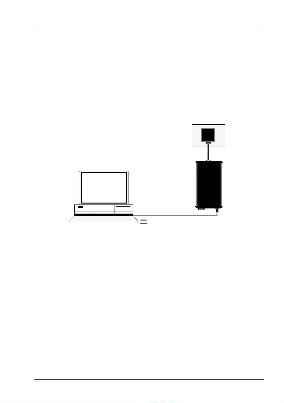
The following figure shows how the BDI2000 interface is connected between the host and the target:
Target System
ARM
JTAG Interface
UNIX / PC Host
GNU Debugger
(GDB)
Ethernet (10 BASE-T)
1.1 BDI2000
The BDI2000 is the main part of the bdiGDB system. This small box implements the interface between the JTAG pins of the target CPU and a 10Base-T ethernet connector. The firmware and the
programable logic of the BDI2000 can be updated by the user with a simple Windows / Linux configuration program. The BDI2000 supports 1.8 – 5.0 Volts target systems (3.0 – 5.0 Volts target systems
with Rev. A/B).
.
BDI2000
AAAAbbbbaaaattttrrrroooonnnn AAAAGGGG
SSSSwwwwiiiissssssss MMMMaaaaddddee
ee
© Copyright 1997-2007 by ABATRON AG Switzerland V 1.04
Page 5

bdi
GDB
for GNU Debugger, BDI2000 (ARM11/Cortex-A8) User Manual 5
1.2 BDI Configuration
As an initial setup, the IP address of the BDI2000, the IP address of the host with the configuration
file and the name of the configuration file is stored within the flash of the BDI2000.
Every time the BDI2000 is powered on, it reads the configuration file via TFTP.
Following an example of a typical configuration file:
; bdiGDB configuration for ARM Integrator CM1136JF-S
; -------------------------------------------------;
[INIT]
WM32 0x1000000C 0x00000005 ;REMAP=1, MISC LED ON
;
[TARGET]
CPUTYPE ARM1136
CLOCK 1 ;JTAG clock (0=Adaptive,1=16MHz,2=8MHz,3=4MHz, ...)
POWERUP 3000 ;start delay after power-up detected in ms
ENDIAN LITTLE ;memory model (LITTLE | BIG)
VECTOR CATCH 0x1f ;catch D_Abort, P_Abort, SWI, Undef and Reset
BREAKMODE HARD ;SOFT or HARD
;
SCANPRED 0 0 ;no JTAG devices before the ARM1136
SCANSUCC 1 4 ;the ETMBUF after the ARM1136 core
;
[HOST]
IP 151.120.25.119
FILE E:\cygwin\home\demo\pid7t\fibo.x
FORMAT ELF
LOAD MANUAL ;load file MANUAL or AUTO after reset
[FLASH]
WORKSPACE 0x00001000 ;workspace in target RAM for fast programming algorithm
CHIPTYPE AM29BX8 ;Flash type (AM29F | AM29BX8 | AM29BX16 | I28BX8 | I28BX16)
CHIPSIZE 0x100000 ;The size of one flash chip in bytes
BUSWIDTH 32 ;The width of the flash memory bus in bits (8 | 16 | 32)
FILE $arm1136.cfg
FORMAT BIN 0x00010000
[REGS]
FILE $reg1136.def
Based on the information in the configuration file, the target is automatically initialized after every reset.
© Copyright 1997-2007 by ABATRON AG Switzerland V 1.04
Page 6
bdi
GDB
for GNU Debugger, BDI2000 (ARM11/Cortex-A8) User Manual 6
2 Installation
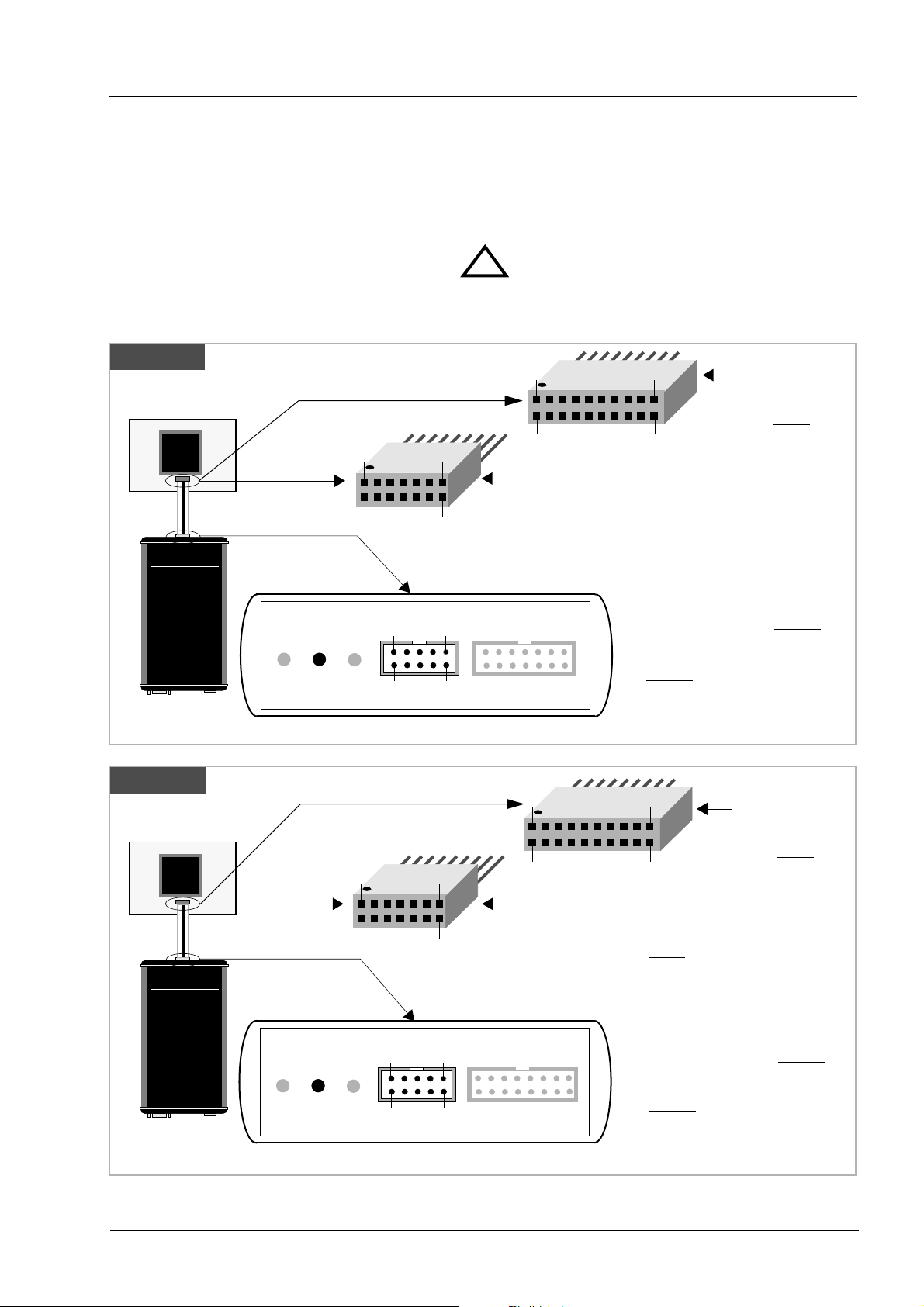
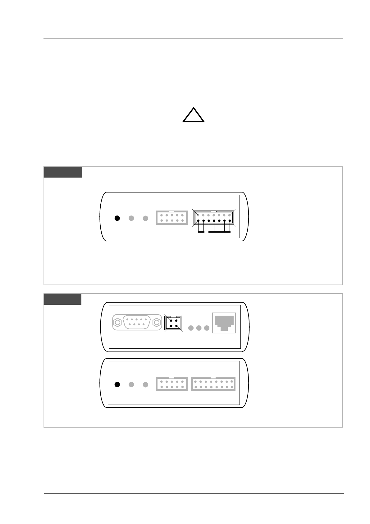
2.1 Connecting the BDI2000 to Target
The enclosed cables to the target system are designed for the ARM Development Boards. In case
where the target system has the same connector layout, the cable (14 pin or 20 pin) can be directly
connected.
!
In order to ensure reliable operation of the BDI (EMC, runtimes, etc.) the target cable length must not
exceed 20 cm (8").
Rev. A
Target System
BDI2000
AAAAbbbbaaaattttrrrroooonnnn AAAAGGGG
Rev. B/C
Target System
BDI2000
AAAAbbbbaaaattttrrrroooonnnn AAAAGGGG
ARM
ARM
1
2
BDI TRGT MODE BDI MAIN BDI OPTION
ee
SSSSwwwwiiiissssssss MMMMaaaaddddee
The green LED «TRGT» marked light up when target is powered up
1
2
BDI TRGT MODE TARGET A TARGET B
ee
SSSSwwwwiiiissssssss MMMMaaaaddddee
The green LED «TRGT» marked light up when target is powered up
9
10
13
14
9 1
10
13
14
1
2
2
1
2
1
2
19
20
14 pin Target
Connector
1 - Vcc Target
2 - GROUND
3 - TRST
4 - GROUND
5 - TDI
6 - NC
7 - TMS
8 - NC
9 - TCK
10 - NC
11 - TDO
12 - RESET
13 - NC
14 - NC
19
20
14 pin Target
Connector
1 - Vcc Target
2 - GROUND
3 - TRST
4 - GROUND
5 - TDI
6 - NC
7 - TMS
8 - NC
9 - TCK
10 - NC
11 - TDO
12 - RESET
13 - NC
14 - NC
20 pin Multi-ICE
Connector
1 - Vcc Target
2 - NC
3 - TRST
4 - NC
5 - TDI
6 - NC
7 - TMS
8 - GROUND
9 - TCK
10 - GROUND
11 - NC
12 - NC
13 - TDO
14 - NC
15 - RESET
16 - NC
17 - NC
18 - NC
19 - NC
20 - NC
20 pin Multi-ICE
Connector
1 - Vcc Target
2 - NC
3 - TRST
4 - NC
5 - TDI
6 - NC
7 - TMS
8 - GROUND
9 - TCK
10 - GROUND
11 - NC
12 - NC
13 - TDO
14 - NC
15 - RESET
16 - NC
17 - NC
18 - NC
19 - NC
20 - NC
For BDI MAIN / TARGET A connector signals see table on next page.
© Copyright 1997-2007 by ABATRON AG Switzerland V 1.04
Page 7

bdi
GDB
for GNU Debugger, BDI2000 (ARM11/Cortex-A8) User Manual 7
BDI MAIN / TARGET A Connector Signals
Pin Name Describtion
1 reserved This pin is currently not used.
2 TRST
3+5 GND
4 TCK
6 TMS
7 RESET
8 TDI
9 Vcc Target
10 TDO
JTAG Test Reset
This open-drain / push-pull output of the BDI2000 resets the JTAG TAP controller on the
target. Default driver type is open-drain.
System Ground
JTAG Test Clock
This output of the BDI2000 connects to the target TCK line.
JTAG Test Mode Select
This output of the BDI2000 connects to the target TMS line.
This open collector output of the BDI2000 is used to reset the target system.
JTAG Test Data In
This output of the BDI2000 connects to the target TDI line.
1.8 – 5.0V:
This is the target reference voltage. It indicates that the target has power and it is also used
to create the logic-level reference for the input comparators. It also controls the output logic
levels to the target. It is normally fed from Vdd I/O on the target board.
3.0 – 5.0V with Rev. A/B :
This input to the BDI2000 is used to detect if the target is powered up. If there is a current
limiting resistor between this pin and the target Vdd, it should be 100 Ohm or less.
JTAG Test Data Out
This input to the BDI2000 connects to the target TDO line.
The BDI2000 works also with targets which have no dedicated TRST
pin. For this kind of targets, the
BDI cannot force the target to debug mode immediately after reset. The target always begins execution of application code until the BDI has finished programming the Debug Control Register.
© Copyright 1997-2007 by ABATRON AG Switzerland V 1.04
Page 8

bdi
GDB
2.1.1 Changing Target Processor Type
Before you can use the BDI2000 with an other target processor type (e.g. ARM <--> PPC), a new
setup has to be done (see chapter 2.5). During this process the target cable must be disconnected
from the target system. The BDI2000 needs to be supplied with 5 Volts via the BDI OPTION connector (Rev. A) or via the POWER connector (Rev. B/C). For more information see chapter 2.2.1
«External Power Supply»).
To avoid data line conflicts, the BDI2000 must be disconnected from the target system while
programming the logic for an other target CPU.
for GNU Debugger, BDI2000 (ARM11/Cortex-A8) User Manual 8
!
© Copyright 1997-2007 by ABATRON AG Switzerland V 1.04
Page 9
bdi
GDB
for GNU Debugger, BDI2000 (ARM11/Cortex-A8) User Manual 9
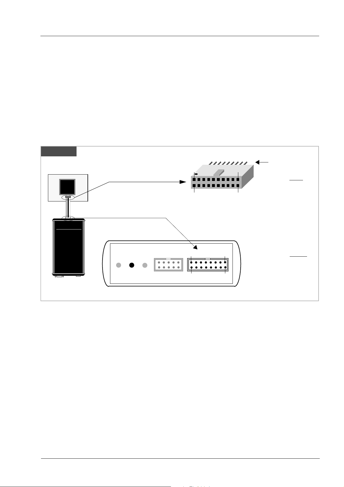
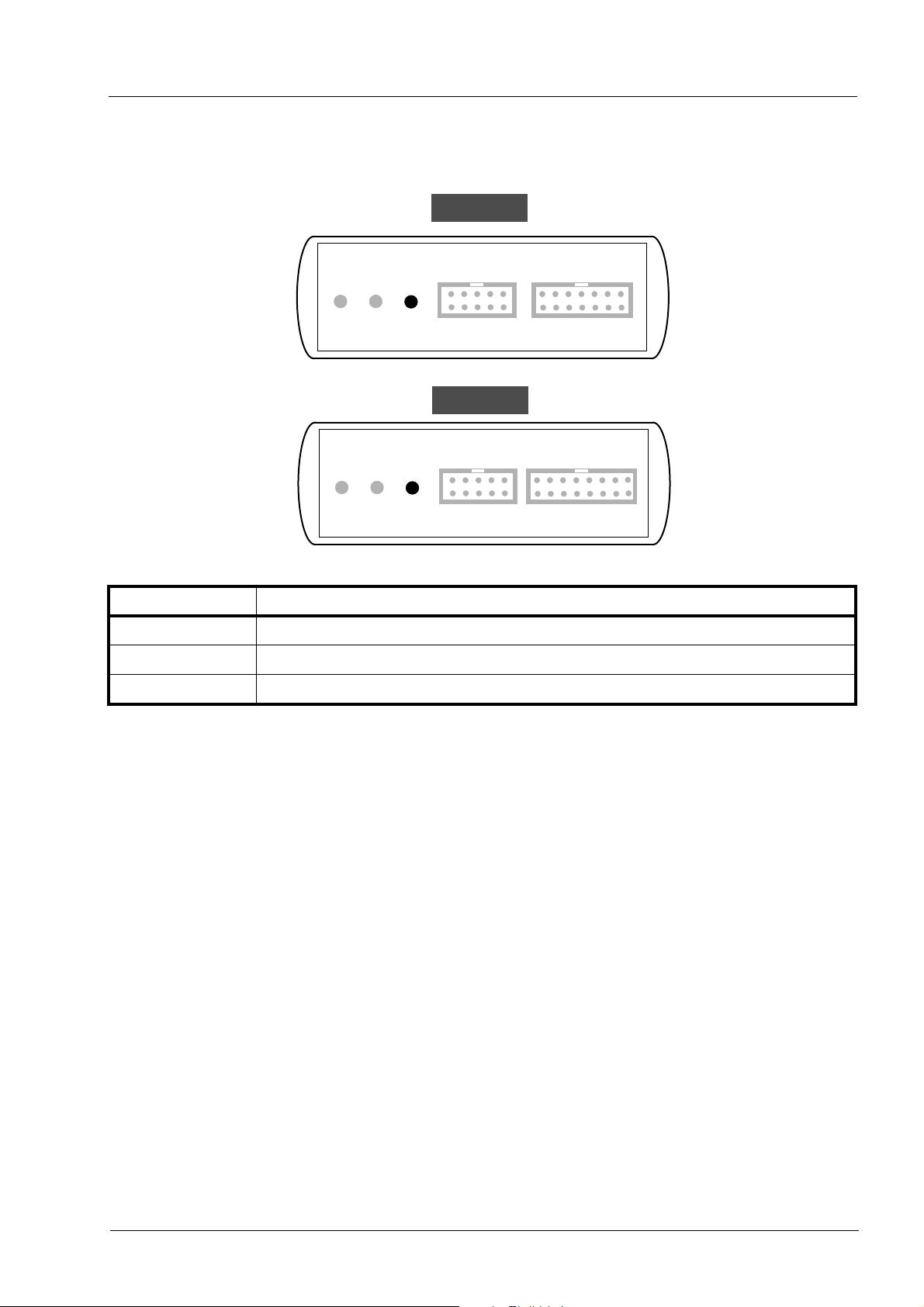
2.1.2 Adaptive Clocking
Adaptive clocking is a feature which ensures that the BDI2000 never loses synchronization with the
target device, whatever the target clock speed is. To achieve this, BDI2000 uses two signals TCK and
RTCK. When adaptive clocking is selected, BDI2000 issues a TCK signal and waits for the Returned
TCK (RTCK) to come back. BDI2000 does not progress to the next TCK until RTCK is received. For
more information about adaptive clocking see ARM documentation.
Note :
Adaptive clocking is only supported with BDI2000 Rev.B/C and a special target cable. This special
cable can be ordered separately from Abatron.
Rev. B/C
Target System
BDI2000
AAAAbbbbaaaattttrrrroooonnnn AAAAGGGG
ARM
SSSSwwwwiiiissssssss MMMMaaaaddddee
1
2
BDI TRGT MODE TARGET A TARGET B
ee
The green LED «TRGT» marked light up when target is powered up
15 1
16
20 pin Multi-ICE
Connector
19
20
2
1 - Vcc Target
2 - NC
3 - TRST
4 - NC
5 - TDI
6 - NC
7 - TMS
8 - GROUND
9 - TCK
10 - GROUND
11 - RTCK
12 - NC
13 - TDO
14 - NC
15 - RESET
16 - NC
17 - NC
18 - NC
19 - NC
20 - NC
For TARGET B connector signals see table on next page.
© Copyright 1997-2007 by ABATRON AG Switzerland V 1.04
Page 10

bdi
GDB
for GNU Debugger, BDI2000 (ARM11/Cortex-A8) User Manual 10
BDI TARGET B Connector Signals:
Pin Name Describtion
1 TDO
2 reserved
3 TDI
4 reserved
5RTCK Returned JTAG Test Clock
6 Vcc Target 1.8 – 5.0V:
7 TCK JTAG Test Clock
8 TRST
JTAG Test Data Out
This input to the BDI2000 connects to the target TDO line.
JTAG Test Data In
This output of the BDI2000 connects to the target TDI line.
This input to the BDI2000 connects to the target RTCK line.
This is the target reference voltage. It indicates that the target has power and it is also used
to create the logic-level reference for the input comparators. It also controls the output logic
levels to the target. It is normally fed from Vdd I/O on the target board.
3.0 – 5.0V with Rev. A/B :
This input to the BDI2000 is used to detect if the target is powered up. If there is a current
limiting resistor between this pin and the target Vdd, it should be 100 Ohm or less.
This output of the BDI2000 connects to the target TCK line.
JTAG Test Reset
This open-drain / push-pull output of the BDI2000 resets the JTAG TAP controller on the
target. Default driver type is open-drain.
9 TMS JTAG Test Mode Select
This output of the BDI2000 connects to the target TMS line.
10 reserved
11 reserved
12 GROUND System Ground
13 RESET
14 reseved
15 reseved
16 GROUND System Ground
System Reset
This open-drain output of the BDI2000 is used to reset the target system.
© Copyright 1997-2007 by ABATRON AG Switzerland V 1.04
Page 11
bdiGDB
for GNU Debugger, BDI2000 (ARM11/Cortex-A8) User Manual 11
2.2 Connecting the BDI2000 to Power Supply
2.2.1 External Power Supply
The BDI2000 needs to be supplied with 5 Volts (max. 1A) via the BDI OPTION connector (Rev. A)
or via POWER connector (Rev. B/C). The available power supply from Abatron (option) or the enclosed power cable can be directly connected. In order to ensure reliable operation of the BDI2000,
keep the power supply cable as short as possible.
!
For error-free operation, the power supply to the BDI2000 must be between 4.75V and 5.25V DC.
The maximal tolerable supply voltage is 5.25 VDC. Any higher voltage or a wrong polarity
might destroy the electronics.
Rev. A
The green LED «BDI» marked light up when 5V power is connected to the BDI2000
Rev. B/C
Rev. B Version
BDI TRGT MODE BDI MAIN BDI OPTION
GND 3
4
RS232 POWER LI TX RX 10 BASE-T
13
14
1 Vcc
2
Vcc
GND
BDI OPTION
Connector
1 - NOT USED
2 - GROUND
3 - NOT USED
1
2
4 - GROUND
5 - NOT USED
6 - GROUND
7 - NOT USED
8 - GROUND
9 - NOT USED
10 - GROUND
11 - NOT USED
12 - Vcc (+5V)
13 - Vcc Target (+5V)
14 - Vcc (+5V)
POWER
Connector
1 - Vcc (+5V)
2 - VccTGT
3 - GROUND
4 - NOT USED
BDI TRGT MODE TARGET A TARGET B
The green LED «BDI» marked light up when 5V power is connected to the BDI2000
Please switch on the system in the following sequence:
• 1 --> external power supply
• 2 --> target system
© Copyright 1997-2007 by ABATRON AG Switzerland V 1.04
Page 12

bdiGDB
for GNU Debugger, BDI2000 (ARM11/Cortex-A8) User Manual 12
2.2.2 Power Supply from Target System
The BDI2000 needs to be supplied with 5 Volts (max. 1A) via BDI MAIN target connector (Rev. A) or
via TARGET A connector (Rev. B/C). This mode can only be used when the target system runs with
5V and the pin «Vcc Target» is able to deliver a current up to 1A@5V. For pin description and layout
see chapter 2.1 «Connecting the BDI2000 to Target». Insert the enclosed Jumper as shown in figure
below. Please ensure that the jumper is inserted correctly.
!
For error-free operation, the power supply to the BDI2000 must be between 4.75V and 5.25V DC.
The maximal tolerable supply voltage is 5.25 VDC. Any higher voltage or a wrong polarity
might destroy the electronics.
Rev. A
BDI OPTION
Connector
Rev. B/C
BDI TRGT MODE BDI MAIN BDI OPTION
1
2
1
2
13
14
Jumper
Jumper
The green LEDs «BDI» and «TRGT» marked light up when target is powered up
and the jumper is inserted correctly
3
4
RS232 POWER LI TX RX 10 BASE-T
BDI TRGT MODE TARGET A TARGET B
1 - NOT USED
2 - GROUND
3 - NOT USED
4 - GROUND
5 - NOT USED
6 - GROUND
7 - NOT USED
8 - GROUND
9 - NOT USED
10 - GROUND
11 - NOT USED
12 - Vcc (+5V)
13 - Vcc Target (+5V)
14 - Vcc BDI2000 (+5V)
POWER
Connector
1 - Vcc BDI2000 (+5V)
2 - Vcc Target (+5V)
3 - GROUND
4 - NOT USED
The green LEDs «BDI» and «TRGT» marked light up when target is powered up
and the jumper is inserted correctly
© Copyright 1997-2007 by ABATRON AG Switzerland V 1.04
Page 13
bdiGDB
for GNU Debugger, BDI2000 (ARM11/Cortex-A8) User Manual 13
2.3 Status LED «MODE»
The built in LED indicates the following BDI states:
Rev. A
BDI TRGT MODE BDI MAIN BDI OPTION
Rev. B/C
BDI TRGT MODE TARGET A TARGET B
MODE LED BDI STATES
OFF The BDI is ready for use, the firmware is already loaded.
ON The power supply for the BDI2000 is < 4.75VDC.
BLINK The BDI «loader mode» is active (an invalid firmware is loaded or loading firmware is active).
© Copyright 1997-2007 by ABATRON AG Switzerland V 1.04
Page 14
bdiGDB
for GNU Debugger, BDI2000 (ARM11/Cortex-A8) User Manual 14
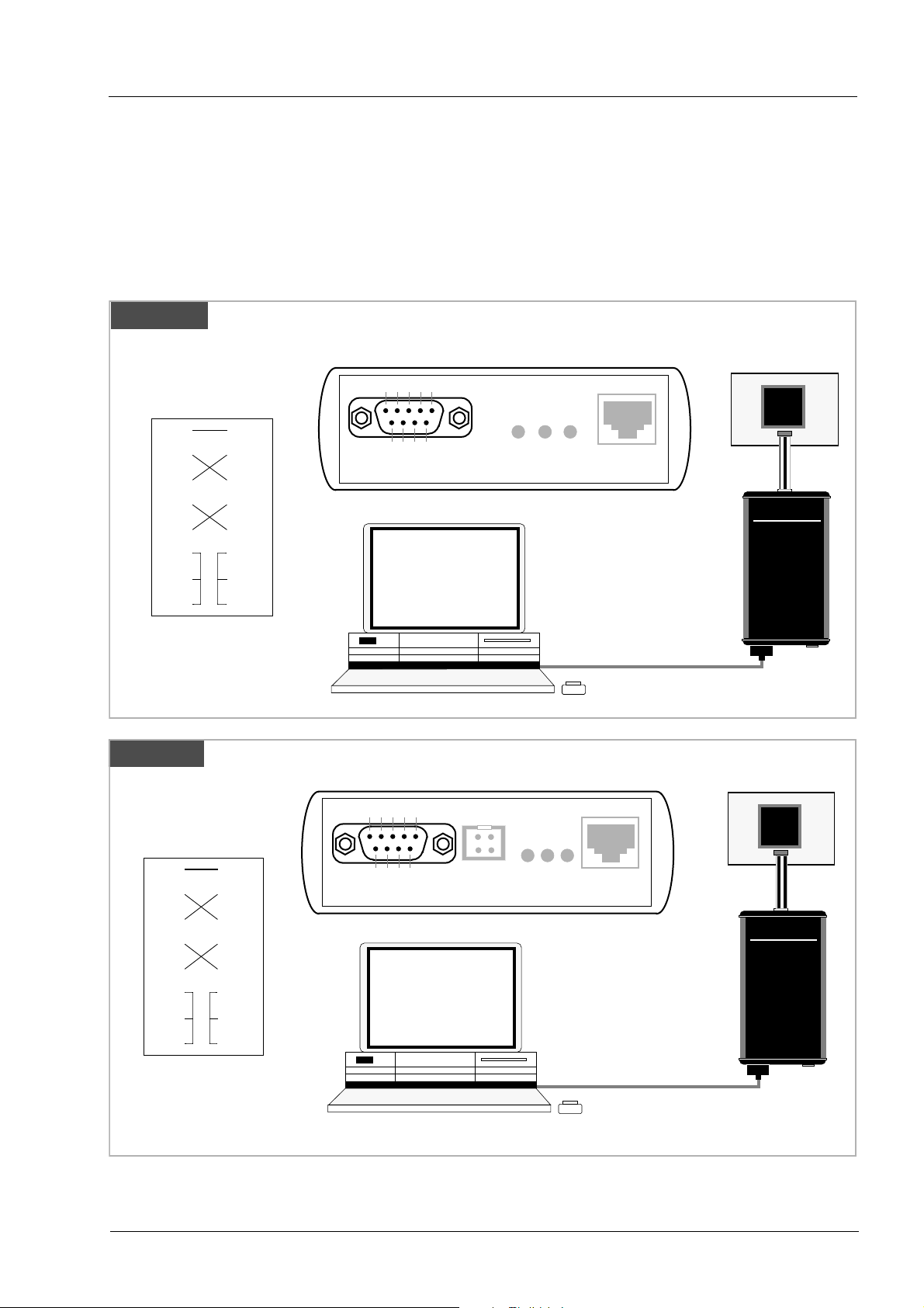
2.4 Connecting the BDI2000 to Host
2.4.1 Serial line communication
Serial line communication is only used for the initial configuration of the bdiGDB system.
The host is connected to the BDI through the serial interface (COM1...COM4). The communication
cable (included) between BDI and Host is a serial cable. There is the same connector pinout for the
BDI and for the Host side (Refer to Figure below).
Rev. A
RS232 Connector
(for PC host)
5 2 3 7 8 6 1 4
GND
RD
TD
RTS
CTS
DSR
DCD
DTR
5 2 3 7 8 6 1 4
GND
RD
TD
RTS
CTS
DSR
DCD
DTR
Rev. B/C
RS232 Connector
(for PC host)
54321
9876
RS232 LI TX RX 10 BASE-T
PC Host
RS232
54321
Target System
ARM
BDI2000
AAAAbbbbaaaattttrrrroooonnnn AAAAGGGG
Target System
ARM
SSSSwwwwiiiissssssss MMMMaaaaddddee
ee
5 2 3 7 8 6 1 4
GND
RD
TD
RTS
CTS
DSR
DCD
DTR
5 2 3 7 8 6 1 4
GND
RD
TD
RTS
CTS
DSR
DCD
DTR
RS232 POWER LI TX RX 10 BASE-T
9876
PC Host
BDI2000
AAAAbbbbaaaattttrrrroooonnnn AAAAGGGG
SSSSwwwwiiiissssssss MMMMaaaaddddee
ee
RS232
© Copyright 1997-2007 by ABATRON AG Switzerland V 1.04
Page 15
bdiGDB
for GNU Debugger, BDI2000 (ARM11/Cortex-A8) User Manual 15
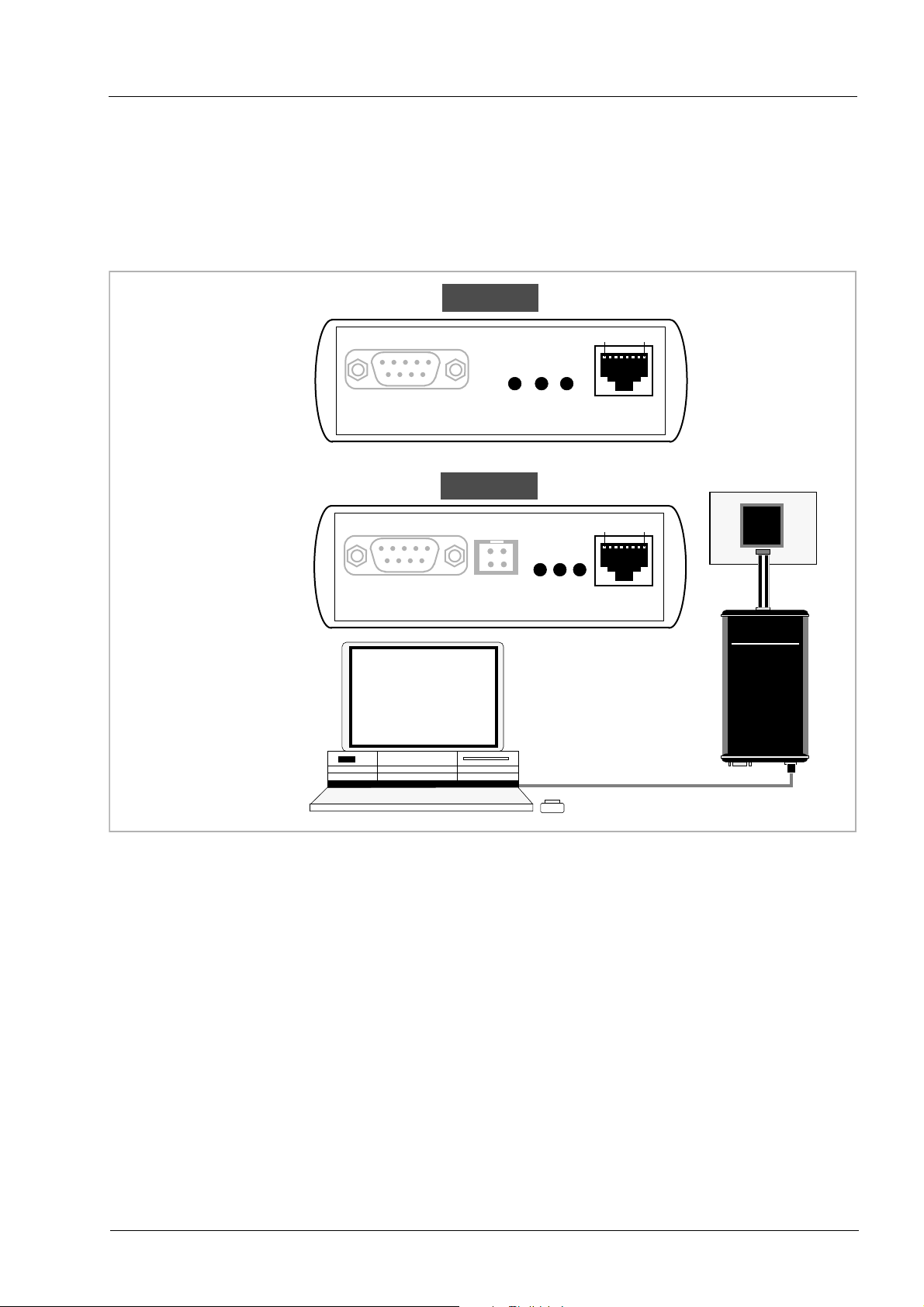
2.4.2 Ethernet communication
The BDI2000 has a built-in 10 BASE-T Ethernet interface (see figure below). Connect an UTP (Unshilded Twisted Pair) cable to the BD2000. For thin Ethernet coaxial networks you can connect a
commercially available media converter (BNC-->10 BASE-T) between your network and the
BDI2000. Contact your network administrator if you have questions about the network.
Rev. A
18
10 BASE-T
Connector
1 - TD+
2 - TD 3 - RD+
4 - NC
5 - NC
6 - RD-
7 - NC
8 - NC
RS232 LI TX RX 10 BASE-T
Rev. B/C
18
Target System
ARM
RS232 POWER LI TX RX 10 BASE-T
BDI2000
PC Host
AAAAbbbbaaaattttrrrroooonnnn AAAAGGGG
Ethernet (10 BASE-T)
The following explains the meanings of the built-in LED lights:
LED Name Description
LI Link When this LED light is ON, data link is successful between the UTP
port of the BDI2000 and the hub to which it is connected.
TX Transmit When this LED light BLINKS, data is being transmitted through the UTP
port of the BDI2000
SSSSwwwwiiiissssssss MMMMaaaaddddee
ee
RX Receive When this LED light BLINKS, data is being received through the UTP
port of the BDI2000
© Copyright 1997-2007 by ABATRON AG Switzerland V 1.04
Page 16

bdiGDB
for GNU Debugger, BDI2000 (ARM11/Cortex-A8) User Manual 16
2.5 Installation of the Configuration Software
On the enclosed diskette you will find the BDI configuration software and the firmware required for
the BDI2000. For Windows NT users there is also a TFTP server included.
The following files are on the diskette.
b20a11gd.exe Windows configuration program
b20a11gd.hlp Windows help file for the configuration program
b20a11gd.xxx Firmware for the BDI2000
armjed20.xxx JEDEC file for the BDI2000 (Rev. A/B) logic device
armjed21.xxx JEDEC file for the BDI2000 (Rev. C) logic device
tftpsrv.exe TFTP server for WindowsNT/ Windows95 (WIN32 console application)
*.cfg Configuration files
*.def Register definition files
bdisetup.zip ZIP Archive with the Setup Tool sources for Linux / UNIX hosts.
Overview of an installation / configuration process:
• Create a new directory on your hard disk
• Copy the entire contents of the enclosed diskette into this directory
• Linux only: extract the setup tool sources and build the setup tool
• Use the setup tool to load/update the BDI firmware/logic
Note: A new BDI has no firmware/logic loaded.
• Use the setup tool to transmit the initial configuration parameters
- IP address of the BDI.
- IP address of the host with the configuration file.
- Name of the configuration file. This file is accessed via TFTP.
- Optional network parameters (subnet mask, default gateway).
Activating BOOTP:
The BDI can get the network configuration and the name of the configuration file also via BOOTP.
For this simple enter 0.0.0.0 as the BDI’s IP address (see following chapters). If present, the subnet
mask and the default gateway (router) is taken from the BOOTP vendor-specific field as defined in
RFC 1533.
With the Linux setup tool, simply use the default parameters for the -c option:
[root@LINUX_1 bdisetup]# ./bdisetup -c -p/dev/ttyS0 -b57
The MAC address is derived from the serial number as follows:
MAC: 00-0C-01-xx-xx-xx , repace the xx-xx-xx with the 6 left digits of the serial number
Example: SN# 93123457 ==>> 00-0C-01-93-12-34
© Copyright 1997-2007 by ABATRON AG Switzerland V 1.04
Page 17

bdiGDB
for GNU Debugger, BDI2000 (ARM11/Cortex-A8) User Manual 17
2.5.1 Configuration with a Linux / Unix host
The firmware / logic update and the initial configuration of the BDI2000 is done with a command line
utility. In the ZIP Archive bdisetup.zip are all sources to build this utility. More information about this
utility can be found at the top in the bdisetup.c source file. There is also a make file included.
Starting the tool without any parameter displays information about the syntax and parameters.
!
To avoid data line conflicts, the BDI2000 must be disconnected from the target system while
programming the logic for an other target CPU (see Chapter 2.1.1).
Following the steps to bring-up a new BDI2000:
1. Build the setup tool:
The setup tool is delivered only as source files. This allows to build the tool on any Linux / Unix host.
To build the tool, simply start the make utility.
[root@LINUX_1 bdisetup]# make
cc -O2 -c -o bdisetup.o bdisetup.c
cc -O2 -c -o bdicnf.o bdicnf.c
cc -O2 -c -o bdidll.o bdidll.c
cc -s bdisetup.o bdicnf.o bdidll.o -o bdisetup
2. Check the serial connection to the BDI:
With "bdisetup -v" you may check the serial connection to the BDI. The BDI will respond with information about the current loaded firmware and network configuration.
Note: Login as root, otherwise you probably have no access to the serial port.
[root@LINUX_1 bdisetup]# ./bdisetup -v -p/dev/ttyS0 -b57
BDI Type : BDI2000 Rev.C (SN: 92152150)
Loader : V1.05
Firmware : unknown
Logic : unknown
MAC : 00-0c-01-92-15-21
IP Addr : 255.255.255.255
Subnet : 255.255.255.255
Gateway : 255.255.255.255
Host IP : 255.255.255.255
Config : ??????????????????
3. Load/Update the BDI firmware/logic:
With "bdisetup -u" the firmware is loaded and the CPLD within the BDI2000 is programmed. This configures the BDI for the target you are using. Based on the parameters -a and -t, the tool selects the
correct firmware / logic files. If the firmware / logic files are in the same directory as the setup tool,
there is no need to enter a -d parameter.
[root@LINUX_1 bdisetup]# ./bdisetup -u -p/dev/ttyS0 -b57 -aGDB -tARM11
Connecting to BDI loader
Erasing CPLD
Programming firmware with ./b20armgd.103
Programming CPLD with ./armjed21.102
© Copyright 1997-2007 by ABATRON AG Switzerland V 1.04
Page 18

bdiGDB
for GNU Debugger, BDI2000 (ARM11/Cortex-A8) User Manual 18
4. Transmit the initial configuration parameters:
With "bdisetup -c" the configuration parameters are written to the flash memory within the BDI.
The following parameters are used to configure the BDI:
BDI IP Address The IP address for the BDI2000. Ask your network administrator for as-
signing an IP address to this BDI2000. Every BDI2000 in your network
needs a different IP address.
Subnet Mask The subnet mask of the network where the BDI is connected to. A subnet
mask of 255.255.255.255 disables the gateway feature. Ask your network
administrator for the correct subnet mask. If the BDI and the host are in
the same subnet, it is not necessary to enter a subnet mask.
Default Gateway Enter the IP address of the default gateway. Ask your network administra-
tor for the correct gateway IP address. If the gateway feature is disabled,
you may enter 255.255.255.255 or any other value.
Config - Host IP Address Enter the IP address of the host with the configuration file. The configura-
tion file is automatically read by the BDI2000 after every start-up.
Configuration file Enter the full path and name of the configuration file. This file is read via
TFTP. Keep in mind that TFTP has it’s own root directory (usual /tftpboot).
You can simply copy the configuration file to this directory and the use the
file name without any path.
For more information about TFTP use "man tftpd".
[root@LINUX_1 bdisetup]# ./bdisetup -c -p/dev/ttyS0 -b57 \
> -i151.120.25.101 \
> -h151.120.25.118 \
> -feval7t.cnf
Connecting to BDI loader
Writing network configuration
Writing init list and mode
Configuration passed
5. Check configuration and exit loader mode:
The BDI is in loader mode when there is no valid firmware loaded or you connect to it with the setup
tool. While in loader mode, the Mode LED is flashing. The BDI will not respond to network requests
while in loader mode. To exit loader mode, the "bdisetup -v -s" can be used. You may also power-off
the BDI, wait some time (1min.) and power-on it again to exit loader mode.
[root@LINUX_1 bdisetup]# ./bdisetup -v -p/dev/ttyS0 -b57 -s
BDI Type : BDI2000 Rev.C (SN: 92152150)
Loader : V1.05
Firmware : V1.03 bdiGDB for ARM11
Logic : V1.02 ARM
MAC : 00-0c-01-92-15-21
IP Addr : 151.120.25.101
Subnet : 255.255.255.255
Gateway : 255.255.255.255
Host IP : 151.120.25.118
Config : eval7t.cnf
The Mode LED should go off, and you can try to connect to the BDI via Telnet.
[root@LINUX_1 bdisetup]# telnet 151.120.25.101
© Copyright 1997-2007 by ABATRON AG Switzerland V 1.04
Page 19

bdiGDB
for GNU Debugger, BDI2000 (ARM11/Cortex-A8) User Manual 19
2.5.2 Configuration with a Windows host
First make sure that the BDI is properly connected (see Chapter 2.1 to 2.4).
!
To avoid data line conflicts, the BDI2000 must be disconnected from the target system while
programming the logic for an other target CPU (see Chapter 2.1.1).
dialog box «BDI2000 Update/Setup»
Before you can use the BDI2000 together with the GNU debugger, you must store the initial configuration parameters in the BDI2000 flash memory. The following options allow you to do this:
Channel Select the communication port where the BDI2000 is connected during
this setup session.
Baudrate Select the baudrate used to communicate with the BDI2000 loader during
this setup session.
Connect Click on this button to establish a connection with the BDI2000 loader.
Once connected, the BDI2000 remains in loader mode until it is restarted
or this dialog box is closed.
Current Press this button to read back the current loaded BDI2000 software and
logic versions. The current loader, firmware and logic version will be
displayed.
Update This button is only active if there is a newer firmware or logic version
present in the execution directory of the bdiGDB setup software. Press this
button to write the new firmware and/or logic into the BDI2000 flash memory / programmable logic.
© Copyright 1997-2007 by ABATRON AG Switzerland V 1.04
Page 20

bdiGDB
BDI IP Address Enter the IP address for the BDI2000. Use the following format:
Subnet Mask Enter the subnet mask of the network where the BDI is connected to.
Default Gateway Enter the IP address of the default gateway. Ask your network administra-
Config - Host IP Address Enter the IP address of the host with the configuration file. The configura-
Configuration file Enter the full path and name of the configuration file.
for GNU Debugger, BDI2000 (ARM11/Cortex-A8) User Manual 20
xxx.xxx.xxx.xxx e.g.151.120.25.101
Ask your network administrator for assigning an IP address to this
BDI2000. Every BDI2000 in your network needs a different IP address.
Use the following format: xxx.xxx.xxx.xxxe.g.255.255.255.0
A subnet mask of 255.255.255.255 disables the gateway feature.
Ask your network administrator for the correct subnet mask.
tor for the correct gateway IP address. If the gateway feature is disabled,
you may enter 255.255.255.255 or any other value..
tion file is automatically read by the BDI2000 after every start-up.
e.g. D:\ada\target\config\bdi\evs332.cnf
For information about the syntax of the configuration file see the bdiGDB
User manual. This name is transmitted to the TFTP server when reading
the configuration file.
Tr ansmit Click on this button to store the configuration in the BDI2000 flash
memory.
2.5.3 Recover procedure
In rare instances you may not be able to load the firmware in spite of a correctly connected BDI (error
of the previous firmware in the flash memory). Before carrying out the following procedure, check
the possibilities in Appendix «Troubleshooting». In case you do not have any success with the
tips there, do the following:
• Switch OFF the power supply for the BDI and open the unit as
described in Appendix «Maintenance»
• Place the jumper in the «INIT MODE» position
• Connect the power cable or target cable if the BDI is powered
from target system
• Switch ON the power supply for the BDI again and wait until the
LED «MODE» blinks fast
INIT MODE
• Turn the power supply OFF again
• Return the jumper to the «DEFAULT» position
• Reassemble the unit as described in Appendix «Maintenance»
© Copyright 1997-2007 by ABATRON AG Switzerland V 1.04
DEFAULT
Page 21

bdiGDB
for GNU Debugger, BDI2000 (ARM11/Cortex-A8) User Manual 21
2.6 Testing the BDI2000 to host connection
After the initial setup is done, you can test the communication between the host and the BDI2000.
There is no need for a target configuration file and no TFTP server is needed on the host.
• If not already done, connect the bdiGDB system to the network.
• Power-up the BDI2000.
• Start a Telnet client on the host and connect to the BDI2000 (the IP address you entered during initial configuration).
• If everything is okay, a sign on message like «BDI Debugger for ARM» should be displayed
in the Telnet window.
2.7 TFTP server for Windows NT
The bdiGDB system uses TFTP to access the configuration file and to load the application program.
Because there is no TFTP server bundled with Windows NT, Abatron provides a TFTP server application tftpsrv.exe. This WIN32 console application runs as normal user application (not as a system
service).
Command line syntax: tftpsrv [p] [w] [dRootDirectory]
Without any parameter, the server starts in read-only mode. This means, only read access request
from the client are granted. This is the normal working mode. The bdiGDB system needs only read
access to the configuration and program files.
The parameter [p] enables protocol output to the console window. Try it.
The parameter [w] enables write accesses to the host file system.
The parameter [d] allows to define a root directory.
tftpsrv p Starts the TFTP server and enables protocol output
tftpsrv p w Starts the TFTP server, enables protocol output and write accesses are
allowed.
tftpsrv dC:\tftp\ Starts the TFTP server and allows only access to files in C:\tftp and its
subdirectories. As file name, use relative names.
For example "bdi\mpc750.cfg" accesses "C:\tftp\bdi\mpc750.cfg"
You may enter the TFTP server into the Startup group so the server is started every time you logon.
© Copyright 1997-2007 by ABATRON AG Switzerland V 1.04
Page 22

bdiGDB
for GNU Debugger, BDI2000 (ARM11/Cortex-A8) User Manual 22
3 Using bdiGDB
3.1 Principle of operation
The firmware within the BDI handles the GDB request and accesses the target memory or registers
via the JTAG interface. There is no need for any debug software on the target system. After loading
the code via TFTP debugging can begin at the very first assembler statement.
Whenever the BDI system is powered-up the following sequence starts:
Power On
initial
configuration
valid?
yes
Get configuration file
via TFTP
Process target init list
Load program code
via TFTP and set the PC
RUN selected?
no
activate BDI2000 loader
Power OFF
Start loaded program code
Process GDB request
Power OFF
© Copyright 1997-2007 by ABATRON AG Switzerland V 1.04
Page 23

bdiGDB
for GNU Debugger, BDI2000 (ARM11/Cortex-A8) User Manual 23
3.2 Configuration File
The configuration file is automatically read by the BDI2000 after every power on.
The syntax of this file is as follows:
; comment
[part name]
core# identifier parameter1 parameter2 ..... parameterN ; comment
core# identifier parameter1 parameter2 ..... parameterN
.....
[part name]
core# identifier parameter1 parameter2 ..... parameterN
core# identifier parameter1 parameter2 ..... parameterN
.....
etc.
Numeric parameters can be entered as decimal (e.g. 700) or as hexadecimal (0x80000).
The core# is optional. If not present the BDI assume core #0. See also chapter "Multi-Core Support".
© Copyright 1997-2007 by ABATRON AG Switzerland V 1.04
Page 24

bdiGDB
for GNU Debugger, BDI2000 (ARM11/Cortex-A8) User Manual 24
3.2.1 Part [INIT]
The part [INIT] defines a list of commands which are be executed every time the target comes out of
reset (except in STARTUP RUN mode). The commands are used to get the target ready for loading
the program file.
WGPR register value Write value to the selected general purpose register.
register the register number 0 .. 15
value the value to write into the register
Example: WGPR 0 5
WREG name value Write value to the selected CPU register by name
name the register name (CPSR)
value the value to write into the register
Example: WREG CPSR 0x600000D3
WCPn register value Write value to the selected Coprocessor register.
nthe CP number (0 .. 15)
register the register number (see chapter CPx registers)
value the value to write into the register
Example: WCP15 2 0x00004000 ; set Translation Base 0
WM8 address value Write a byte (8bit) to the selected memory place.
address the memory address
value the value to write to the target memory
Example: WM8 0xFFFFFA21 0x04 ; SYPCR: watchdog disable ...
WM16 address value Write a half word (16bit) to the selected memory place.
address the memory address
value the value to write to the target memory
Example: WM16 0x02200200 0x0002 ; TBSCR
WM32 address value Write a word (32bit) to the selected memory place.
address the memory address
value the value to write to the target memory
Example: WM32 0x02200000 0x01632440 ; SIUMCR
WAPB address value Cortex-A8: Write a word (32bit) to the Debug APB memory.
address the APB memory address
value the value to write to the APB memory
Example: WAPB 0xd4012014 0x08000014 ; RCSR
© Copyright 1997-2007 by ABATRON AG Switzerland V 1.04
Page 25

bdiGDB
WBIN address filename Write a binary image to the selected memory place. The binary image is
RM8 address value Read a byte (8bit) from the selected memory place.
RM16 address value Read a half word (16bit) from the selected memory place.
RM32 address value Read a word (32bit) from the selected memory place.
for GNU Debugger, BDI2000 (ARM11/Cortex-A8) User Manual 25
read via TFTP from the host. Up to 4 such entries are supported.
address the memory address
filename the filename including the full path
Example: WBIN 0x4000 pagetable.bin
address the memory address
Example: RM8 0x00000000
address the memory address
Example: RM16 0x00000000
address the memory address
Example: RM32 0x00000000
MMAP start end Because a memory access to an invalid memory space via JTAG leads to
a deadlock, this entry can be used to define up to 32 valid memory ranges.
If at least one memory range is defined, the BDI checks against this
range(s) and avoids accessing of not mapped memory ranges.
start the start address of a valid memory range
end the end address of this memory range
Example: MMAP 0xFFE00000 0xFFFFFFFF ;Boot ROM
DELAY value Delay for the selected time.
value the delay time in milliseconds (1...30000)
Example: DELAY 500 ; delay for 0.5 seconds
CLOCK value This entry allows to change the JTAG clock frequency during processing
of the init list. But the final JTAG clock after processing the init list is taken
from the CLOCK entry in the [TARGET] section. This entry maybe of interest to speed-up JTAG clock as soon as possible (after PLL setup).
value see CLOCK parameter in [TARGET] section
Example: CLOCK 2 ; switch to 8 MHz JTAG clock
© Copyright 1997-2007 by ABATRON AG Switzerland V 1.04
Page 26

bdiGDB
Using a startup program to initialize the target system:
For targets where initialization can not be done with a simple initialization list, there is the possibility
to download and execute a special startup code. The startup code must be present in a file on the
host. The last instruction in this startup code should be a BKPT. After processing the initlist, the BDI
downloads this startup code to RAM, starts it and waits until it completes. If there is no BKPT instruction in the startup code, the BDI terminates it after a timeout of 5 seconds.
FILE filename The name of the file with the startup code. This name is used to access
FORMAT format The format of the startup file. Currently COFF, S-Record, a.out, Binary and
START address The address where to start the startup code. If this value is not defined and
for GNU Debugger, BDI2000 (ARM11/Cortex-A8) User Manual 26
the startup code via TFTP.
filename the filename including the full path
Example: FILE F:\gdb\target\config\pid7t\startup.hex
ELF file formats are supported. If the startup code is already stored in
ROM on the target, select ROM as the format.
format COFF, SREC, AOUT, BIN, ELF or ROM
Example: FORMAT COFF
the core is not in ROM, the address is taken from the code file. If this value
is not defined and the core is already in ROM, the PC will not be set before
starting the code.
address the address where to start the startup code
Example: START 0x10000
Note:
If an init list and a startup code file are present, the init list is processed first and then the startup code
is loaded and executed. Therefore it is possible first to enable some RAM with the init list before the
startup code is loaded and executed.
[INIT]
WM32 0x0B000020 0x00000000 ;Clear Reset Map
FILE d:\gdb\bdi\startup.hex
FORMAT SREC
START 0x100
© Copyright 1997-2007 by ABATRON AG Switzerland V 1.04
Page 27

bdiGDB
for GNU Debugger, BDI2000 (ARM11/Cortex-A8) User Manual 27
3.2.2 Part [TARGET]
The part [TARGET] defines some target specific values.
CPUTYPE type This value gives the BDI information about the connected CPU.
type The CPU type from the following list:
ARM1136, CORTEX-A8, OMAP3430
Example: CPUTYPE ARM1136
CLOCK main [init] [SLOW]With this value(s) you can select the JTAG clock rate the BDI2000 uses
when communication with the target CPU. The "main" entry is used after
processing the initialization list. The "init" value is used after target reset
until the initialization list is processed. If there is no "init" value defined, the
"main" value is used all the times.
Adaptive clocking is only supported with BDI2000 Rev.B/C and needs a
special target connector cable. Add also SLOW if the CPU clock frequency
may fall below 6 MHz during adaptive clocking.
main,init: 0 = Adaptive
1 = 16 MHz 6 = 200 kHz
2 = 8 MHz 7 = 100 kHz
3 = 4 MHz 8 = 50 kHz
4 = 1 MHz 9 = 20 kHz
5 = 500 kHz 10 = 10 kHz
Example: CLOCK 1 ; JTAG clock is 16 MHz
RESET type [time] Normally the BDI drives the reset line during startup. If reset type is NONE
or SOFT, the BDI does not assert a hardware reset during startup. If reset
type SOFT is supported depends on the connected target.
type NONE
SOFT (soft reset via a debug register)
HARD (default)
time The time in milliseconds the BDI assert the reset signal.
Example: RESET NONE ; no reset during startup
RESET SOFT ; reset ARM core via RCSR
RESET HARD 1000 ; assert RESET for 1 second
TRST type Normally the BDI uses an open drain driver for the TRST signal. This is in
accordance with the ARM recommendation. For boards where TRST is
simply pulled low with a weak resistor, TRST will always be asserted and
JTAG debugging is impossible. In that case, the TRST driver type can be
changed to push-pull. Then the BDI actively drives also high level.
type OPENDRAIN (default)
PUSHPULL
Example: TRST PUSHPULL ; Drive TRST also high
© Copyright 1997-2007 by ABATRON AG Switzerland V 1.04
Page 28

bdiGDB
STARTUP mode [runtime] This parameter selects the target startup mode. The following modes are
WAKEUP time This entry in the init list allows to define a delay time (in ms) the BDI inserts
for GNU Debugger, BDI2000 (ARM11/Cortex-A8) User Manual 28
supported:
HALT This default mode tries to forces the target to debug
mode immediately out of reset. If successful, no code is
executed after reset.
STOP In this mode, the BDI lets the target execute code for
"runtime" milliseconds after reset. This mode is useful
when monitor code should initialize the target system.
RUNAfter reset, the target executes code until stopped by the
Te lnet "halt" command. The init list is not processed in
this mode.
Example: STARTUP STOP 3000 ; let the CPU run for 3 seconds
between releasing the reset line and starting communicating with the target. This delay is necessary when a target needs some wake-up time after
a reset.
time the delay time in milliseconds
Example: WAKEUP 3000 ; insert 3sec wake-up time
BDIMODE mode param This parameter selects the BDI debugging mode. The following modes are
supported:
LOADONLY Loads and starts the application code. No debugging via
JTAG interface.
AGENT The debug agent runs within the BDI. There is no need
for any debug software on the target. This mode accepts
a second parameter. If RUN is entered as a second pa-
rameter, the loaded application will be started immedi-
ately, otherwise only the PC is set and BDI waits for GDB
requests.
Example: BDIMODE AGENT RUN
ENDIAN format This entry defines the endiannes of the memory system.
format The endiannes of the target memory:
LITTLE (default)
BIG
Example: ENDIAN LITTLE
VECTOR CATCH mask When this line is present, the BDI catches exceptions. The mask is used
to setup the ARM Vector catch register.
mask selects the exceptions to catch
Example: VECTOR CATCH 0x1B ;catch Abort, Undef, Reset
© Copyright 1997-2007 by ABATRON AG Switzerland V 1.04
Page 29

bdiGDB
BREAKMODE mode This parameter defines how breakpoints are implemented.
MEMACCES mode [wait] For Cortex-A8, this parameter defines how memory is accessed. Either
for GNU Debugger, BDI2000 (ARM11/Cortex-A8) User Manual 29
SOFT This is the normal mode. Breakpoints are implemented
by replacing code with a BKPT instruction.
HARD In this mode, the breakpoint hardware is used. Only 6
breakpoints at a time are supported.
Example: BREAKMODE HARD
via the ARM core by executing ld and st instructions or via the AHB access
port. The current mode can also be changed via the Telnet interface. The
optional wait parameter allows to define a time the BDI waits before it expects that a value is ready or written. This allows to optimize download
performance. The wait time is (8 x wait) TCK’s in Run-Test/Idle state.
The following modes are supported:
CORE The CORE (default) mode requires that the core is halt-
ed and makes use of the memory management unit
(MMU) and cache.
AHB The AHB access mode can access memory even when
the core is running but bypasses the MMU and cache.
Example: MEMACCES CORE 5 ; 40 TCK's access delay
SIO port [baudrate] When this line is present, a TCP/IP channel is routed to the BDI’s RS232
connector. The port parameter defines the TCP port used for this BDI to
host communication. You may choose any port except 0 and the default
Te lnet port (23). On the host, open a Telnet session using this port. Now
you should see the UART output in this Telnet session. You can use the
normal Telnet connection to the BDI in parallel, they work completely independent. Also input to the UART is implemented.
port The TCP/IP port used for the host communication.
baudrate The BDI supports 2400 ... 115200 baud
Example: SIO 7 9600 ;TCP port for virtual IO
DCC port When this line is present, a TCP/IP channel is routed to the ARM debug
communication channel (DCC). The port parameter defines the TCP port
used for this BDI to host communication. You may choose any port except
0 and the default Telnet port (23). On the host, open a Telnet session using
this port. Now you should see the DCC output in this Telnet session. You
can use the normal Telnet connection to the BDI in parallel, they work
completely independent. Also input to DCC is implemented.
port The TCP/IP port used for the host communication.
Example: DCC 7 ;TCP port for DCC I/O
© Copyright 1997-2007 by ABATRON AG Switzerland V 1.04
Page 30

bdiGDB
Daisy chained JTAG devices:
For ARM targets, the BDI can also handle systems with multiple devices connected to the JTAG scan
chain. In order to put the other devices into BYPASS mode and to count for the additional bypass
registers, the BDI needs some information about the scan chain layout. Enter the number (count) and
total instruction register (irlen) length of the devices present before the ARM chip (Predecessor). Enter the appropriate information also for the devices following the ARM chip (Successor):
SCANPRED count irlen This value gives the BDI information about JTAG devices present before
SCANSUCC count irlen This value gives the BDI information about JTAG devices present after the
for GNU Debugger, BDI2000 (ARM11/Cortex-A8) User Manual 30
the ARM chip in the JTAG scan chain.
count The number of preceding devices
irlen The sum of the length of all preceding instruction regis-
ters (IR).
Example: SCANPRED 1 8 ; one device with an IR length of 8
ARM chip in the JTAG scan chain.
count The number of succeeding devices
irlen The sum of the length of all succeeding instruction reg-
isters (IR).
Example: SCANSUCC 2 12 ; two device with an IR length of 8+4
© Copyright 1997-2007 by ABATRON AG Switzerland V 1.04
Page 31

bdiGDB
for GNU Debugger, BDI2000 (ARM11/Cortex-A8) User Manual 31
Low level JTAG scan chain configuration:
Sometimes it is necessary to configure the test access port (TAP) of the target before the ARM debug
interface is visible and accessible in the usual way. The BDI supports this configuration in a very generic way via the SCANINIT and SCANPOST configuration commands. Both accept a string that defines the JTAG sequences to execute. The following example shows how to use these commands:
; Configure ICEPick module to make ARM926 TAP visible
SCANINIT t1:w1000:t0:w1000: ;toggle TRST
SCANINIT i6=07:d8=89:i6=02: ;connect and select router
SCANINIT d32=81000082: ;set IP control
SCANINIT d32=a018206f: ;configure TAP0
SCANINIT d32=a018216f:cl5: ;enable TAP0, clock 5 times in RTI
SCANINIT i10=ffff ;scan bypass
;
; Between SCANINIT and SCANPOST the ARM ICEBreaker is configured
; and the DBGRQ bit in the ARM debug control register is set.
;
SCANPOST i10=002f: ;IP(router) - ARM(bypass)
SCANPOST d33=0102000106: ;IP control = SysReset
SCANPOST i10=ffff ;scan bypass
The following low level JTAG commands are supported in the string. Use ":" between commands.
I<n>=<...b2b1b0> write IR, b0 is first scanned
D<n>=<...b2b1b0> write DR, b0 is first scanned
n : the number of bits 1..256
bx : a data byte, two hex digits
W<n> wait for n (decimal) micro seconds
T1 assert TRST
T0 release TRST
R1 assert RESET
R0 release RESET
CH<n> clock TCK n (decimal) times with TMS high
CL<n> clock TCK n (decimal) times with TMS low
The following diagram shows the parts of the standard reset sequence that are replaced with the
SCAN string. Only the appropriate part of the reset sequence is replaced. If only a SCANINIT string
is defined, then the standard "post" sequence is still executed.
If (reset mode == hard) Assert reset
Toggle TRST
Execute SCANINIT string
If (reset mode == hard) Delay for reset time
Check if Bypass register(s) present
Read and display ID code
Check if debug module is accessible
If (startup == reset) catch reset exception
If (reset mode == hard) Release reset
Wait until reset is really release
Execute SCANPOST string
Delay for wake-up time
© Copyright 1997-2007 by ABATRON AG Switzerland V 1.04
Page 32

bdiGDB
for GNU Debugger, BDI2000 (ARM11/Cortex-A8) User Manual 32
3.2.3 Part [HOST]
The part [HOST] defines some host specific values.
IP ipaddress The IP address of the host.
ipaddress the IP address in the form xxx.xxx.xxx.xxx
Example: IP 151.120.25.100
FILE filename The default name of the file that is loaded into RAM using the Telnet ’load’
command. This name is used to access the file via TFTP. If the filename
starts with a $, this $ is replace with the path of the configuration file name.
filename the filename including the full path or $ for relative path.
Example: FILE F:\gnu\demo\arm\test.elf
FILE $test.elf
FORMAT format [offset] The format of the image file and an optional load address offset. If the im-
age is already stored in ROM on the target, select ROM as the format. The
optional parameter "offset" is added to any load address read from the image file.
format SREC, BIN, AOUT, ELF, COFF or ROM
Example: FORMAT ELF
FORMAT ELF 0x10000
LOAD mode In Agent mode, this parameters defines if the code is loaded automatically
after every reset.
mode AUTO, MANUAL
Example: LOAD MANUAL
START address The address where to start the program file. If this value is not defined and
the core is not in ROM, the address is taken from the code file. If this value
is not defined and the core is already in ROM, the PC will not be set before
starting the target. This means, the program starts at the normal reset address (0x00000000).
address the address where to start the program file
Example: START 0x10000
DEBUGPORT port [RECONNECT]
The TCP port GDB uses to access the target. If the RECONNECT parameter is present, an open TCP/IP connection (Telnet/GDB) will be closed if
there is a connect request from the same host (same IP address).
port the TCP port number (default = 2001)
Example: DEBUGPORT 2001
© Copyright 1997-2007 by ABATRON AG Switzerland V 1.04
Page 33

bdiGDB
PROMPT string This entry defines a new Telnet prompt. The current prompt can also be
DUMP filename The default file name used for the DUMP command from a Telnet session.
TELNET mode By default the BDI sends echoes for the received characters and supports
for GNU Debugger, BDI2000 (ARM11/Cortex-A8) User Manual 33
changed via the Telnet interface.
Example: PROMPT ARM11>
filename the filename including the full path
Example: DUMP dump.bin
command history and line editing. If it should not send echoes and let the
Te lnet client in "line mode", add this entry to the configuration file.
mode ECHO (default), NOECHO or LINE
Example: TELNET NOECHO ; use old line mode
© Copyright 1997-2007 by ABATRON AG Switzerland V 1.04
Page 34

bdiGDB
for GNU Debugger, BDI2000 (ARM11/Cortex-A8) User Manual 34
3.2.4 Part [FLASH]
The Telnet interface supports programming and erasing of flash memories. The bdiGDB system has
to know which type of flash is used, how the chip(s) are connected to the CPU and which sectors to
erase in case the ERASE command is entered without any parameter.
CHIPTYPE type This parameter defines the type of flash used. It is used to select the cor-
rect programming algorithm.
format AM29F, AM29BX8, AM29BX16, I28BX8, I28BX16,
AT49, AT49X8, AT49X16, STRATAX8, STRATAX16,
MIRROR, MIRRORX8, MIRRORX16,
M58X32, AM29DX16, AM29DX32
Example: CHIPTYPE AM29F
CHIPSIZE size The size of one flash chip in bytes (e.g. AM29F010 = 0x20000). This value
is used to calculate the starting address of the current flash memory bank.
size the size of one flash chip in bytes
Example: CHIPSIZE 0x80000
BUSWIDTH width Enter the width of the memory bus that leads to the flash chips. Do not en-
ter the width of the flash chip itself. The parameter CHIPTYPE carries the
information about the number of data lines connected to one flash chip.
For example, enter 16 if you are using two AM29F010 to build a 16bit flash
memory bank.
with the width of the flash memory bus in bits (8 | 16 | 32)
Example: BUSWIDTH 16
FILE filename The default name of the file that is programmed into flash using the Telnet
’prog’ command. This name is used to access the file via TFTP. If the filename starts with a $, this $ is replace with the path of the configuration file
name. This name may be overridden interactively at the Telnet interface.
filename the filename including the full path or $ for relative path.
Example: FILE F:\gnu\arm\bootrom.hex
FILE $bootrom.hex
FORMAT format [offset] The format of the file and an optional address offset. The optional param-
eter "offset" is added to any load address read from the program file.
format SREC, BIN, AOUT, ELF or COFF
Example: FORMAT SREC
FORMAT ELF 0x10000
WORKSPACE address If a workspace is defined, the BDI uses a faster programming algorithm
that runs out of RAM on the target system. Otherwise, the algorithm is processed within the BDI. The workspace is used for a 1kByte data buffer and
to store the algorithm code. There must be at least 2kBytes of RAM available for this purpose.
address the address of the RAM area
Example: WORKSPACE 0x00000000
© Copyright 1997-2007 by ABATRON AG Switzerland V 1.04
Page 35

bdiGDB
for GNU Debugger, BDI2000 (ARM11/Cortex-A8) User Manual 35
ERASE addr [increment count] [mode [wait]]
The flash memory may be individually erased or unlocked via the Telnet
interface. In order to make erasing of multiple flash sectors easier, you can
enter an erase list. All entries in the erase list will be processed if you enter
ERASE at the Telnet prompt without any parameter. This list is also used
if you enter UNLOCK at the Telnet without any parameters. With the "increment" and "count" option you can erase multiple equal sized sectors
with one entry in the erase list.
address Address of the flash sector, block or chip to erase
increment If present, the address offset to the next flash sector
count If present, the number of equal sized sectors to erase
mode BLOCK, CHIP, UNLOCK
wait The wait time in ms is only used for the unlock mode. Af-
Example: ERASE 0xff040000 ;erase sector 4 of flash
Without this optional parameter, the BDI executes a sec-
tor erase. If supported by the chip, you can also specify
a block or chip erase. If UNLOCK is defined, this entry is
also part of the unlock list. This unlock list is processed
if the Telnet UNLOCK command is entered without any
parameters.
ter starting the flash unlock, the BDI waits until it pro-
cesses the next entry.
ERASE 0xff060000 ;erase sector 6 of flash
ERASE 0xff000000 CHIP ;erase whole chip(s)
ERASE 0xff010000 UNLOCK 100 ;unlock, wait 100ms
ERASE 0xff000000 0x10000 7 ; erase 7 sectors
Example for the ARM PID7T board (AM29F010 in U12):
[FLASH]
WORKSPACE 0x00000000 ;Workspace in target RAM for faster programming algorithm
CHIPTYPE AM29F ;Flash type
CHIPSIZE 0x20000 ;The size of one flash chip in bytes
BUSWIDTH 8 ;The width of the flash memory bus in bits (8 | 16 | 32)
FILE C:\gdb\pid7t\bootrom.hex ;The file to program
ERASE 0x04000000 ;erase sector 0 of flash SIMM
ERASE 0x04004000 ;erase sector 1 of flash SIMM
ERASE 0x04008000 ;erase sector 2 of flash SIMM
ERASE 0x0400C000 ;erase sector 3 of flash SIMM
ERASE 0x04010000 ;erase sector 4 of flash SIMM
ERASE 0x04014000 ;erase sector 5 of flash SIMM
ERASE 0x04018000 ;erase sector 6 of flash SIMM
ERASE 0x0401C000 ;erase sector 7 of flash SIMM
the above erase list maybe replaced with:
ERASE 0x04000000 0x4000 8 ;erase 8 sectors
© Copyright 1997-2007 by ABATRON AG Switzerland V 1.04
Page 36

bdiGDB
for GNU Debugger, BDI2000 (ARM11/Cortex-A8) User Manual 36
Supported Flash Memories:
There are currently 3 standard flash algorithm supported. The AMD, Intel and Atmel AT49 algorithm.
Almost all currently available flash memories can be programmed with one of this algorithm. The
flash type selects the appropriate algorithm and gives additional information about the used flash.
For 8bit only flash: AM29F (MIRROR), I28BX8, AT49
For 8/16 bit flash in 8bit mode: AM29BX8 (MIRRORX8), I28BX8 (STRATAX8), AT49X8
For 8/16 bit flash in 16bit mode: AM29BX16 (MIRRORX16), I28BX16 (STRATAX16), AT49X16
For 16bit only flash: AM29BX16, I28BX16, AT49X16
For 16/32 bit flash in 16bit mode: AM29DX16
For 16/32 bit flash in 32bit mode: AM29DX32
For 32bit only flash: M58X32
Some newer Spansion MirrorBit flashes cannot be programmed with the MIRRORX16 algorithm because of the used unlock address offset. Use S29M32X16 for these flashes.
The AMD and AT49 algorithm are almost the same. The only difference is, that the AT49 algorithm
does not check for the AMD status bit 5 (Exceeded Timing Limits).
Only the AMD and AT49 algorithm support chip erase. Block erase is only supported with the AT49
algorithm. If the algorithm does not support the selected mode, sector erase is performed. If the chip
does not support the selected mode, erasing will fail. The erase command sequence is different only
in the 6th write cycle. Depending on the selected mode, the following data is written in this cycle (see
also flash data sheets): 0x10 for chip erase, 0x30 for sector erase, 0x50 for block erase.
To speed up programming of Intel Strata Flash and AMD MirrorBit Flash, an additional algorithm is
implemented that makes use of the write buffer. This algorithm needs a workspace, otherwise the
standard Intel/AMD algorithm is used.
The following table shows some examples:
Flash x 8 x 16 x 32 Chipsize
Am29F010 AM29F - - 0x020000
Am29F800B AM29BX8 AM29BX16 - 0x100000
Am29DL323C AM29BX8 AM29BX16 - 0x400000
Am29PDL128G - AM29DX16 AM29DX32 0x01000000
Intel 28F032B3 I28BX8 - - 0x400000
Intel 28F640J3A STRATAX8 STRATAX16 - 0x800000
Intel 28F320C3 - I28BX16 - 0x400000
AT49BV040 AT49 - - 0x080000
AT49BV1614 AT49X8 AT49X16 - 0x200000
M58BW016BT - - M58X32 0x200000
SST39VF160 - AT49X16 - 0x200000
Am29LV320M MIRRORX8 MIRRORX16 - 0x400000
© Copyright 1997-2007 by ABATRON AG Switzerland V 1.04
Page 37

bdiGDB
for GNU Debugger, BDI2000 (ARM11/Cortex-A8) User Manual 37
Note:
Some Intel flash chips (e.g. 28F800C3, 28F160C3, 28F320C3) power-up with all blocks in locked
state. In order to erase/program those flash chips, use the init list to unlock the appropriate blocks:
WM16 0xFFF00000 0x0060 unlock block 0
WM16 0xFFF00000 0x00D0
WM16 0xFFF10000 0x0060 unlock block 1
WM16 0xFFF10000 0x00D0
....
WM16 0xFFF00000 0xFFFF select read mode
or use the Telnet "unlock" command:
UNLOCK [<addr> [<delay>]]
addr This is the address of the sector (block) to unlock
delay A delay time in milliseconds the BDI waits after sending the unlock com-
mand to the flash. For example, clearing all lock-bits of an Intel J3 Strata
flash takes up to 0.7 seconds.
If "unlock" is used without any parameter, all sectors in the erase list with the UNLOCK option are
processed.
To clear all lock-bits of an Intel J3 Strata flash use for example:
BDI> unlock 0xFF000000 1000
To erase or unlock multiple, continuos flash sectors (blocks) of the same size, the following Telnet
commands can be used:
ERASE <addr> <step> <count>
UNLOCK <addr> <step> <count>
addr This is the address of the first sector to erase or unlock.
step This value is added to the last used address in order to get to the next sec-
tor. In other words, this is the size of one sector in bytes.
count The number of sectors to erase or unlock.
The following example unlocks all 256 sectors of an Intel Strata flash ( 28F256K3) that is mapped to
0x00000000. In case there are two flash chips to get a 32bit system, double the "step" parameter.
BDI> unlock 0x00000000 0x20000 256
© Copyright 1997-2007 by ABATRON AG Switzerland V 1.04
Page 38

bdiGDB
for GNU Debugger, BDI2000 (ARM11/Cortex-A8) User Manual 38
3.2.5 Part [REGS]
In order to make it easier to access target registers via the Telnet interface, the BDI can read in a
register definition file. In this file, the user defines a name for the register and how the BDI should
access it (e.g. as memory mapped, memory mapped with offset, ...). The name of the register definition file and information for different registers type has to be defined in the configuration file.
The register name, type, address/offset/number and size are defined in a separate register definition
file. This way, you can create one register definition file for a specific target processor that can be
used for all possible positions of the internal memory map. You only have to change one entry in the
configuration file.
An entry in the register definition file has the following syntax:
name type addr size
name The name of the register (max. 12 characters)
type The register type
GPR General purpose register
CP15 Coprocessor 15 register
CP14 Coprocessor 14register
....
CP0 Coprocessor 0 register
MM Absolute direct memory mapped register
DMM1...DMM4 Relative direct memory mapped register
IMM1...IMM4 Indirect memory mapped register
APB APB memory mapped register
addr The address, offset or number of the register
size The size (8, 16, 32) of the register, default is 32
The following entries are supported in the [REGS] part of the configuration file:
FILE filename The name of the register definition file. This name is used to access the
file via TFTP. The file is loaded once during BDI startup.
filename the filename including the full path
Example: FILE C:\bdi\regs\reg40400.def
DMMn base This defines the base address of direct memory mapped registers. This
base address is added to the individual offset of the register.
base the base address
Example: DMM1 0x01000
IMMn addr data This defines the addresses of the memory mapped address and data reg-
isters of indirect memory mapped registers. The address of a IMMn register is first written to "addr" and then the register value is access using
"data" as address.
addr the address of the Address register
data the address of the Data register
Example: IMM1 0x04700000 0x04700004
© Copyright 1997-2007 by ABATRON AG Switzerland V 1.04
Page 39

bdiGDB
for GNU Debugger, BDI2000 (ARM11/Cortex-A8) User Manual 39
Example for a register definition:
Entry in the configuration file:
[REGS]
FILE E:\cygwin\home\bdidemo\arm\reg1136.def
The register definition file:
;
;Coprocessor Register Numbers:
;
; +-----+-+-------+-----+-+-------+
; |opc_2|0| CRm |opc_1|0| nbr |
; +-----+-+-------+-----+-+-------+
;
;The 16bit register number is used to build the appropriate MCR/MRC instruction.
;
;
;name type addr size
;------------------------------------------;
id CP15 0x0000 32 ;ID code
cache CP15 0x2000 32 ;Cache type
tcmstatus CP15 0x4000 32 ;TCM status
tcmtype CP15 0x6000 32 ;TCM type
;
ctr CP15 0x0001 32 ;Control
aux CP15 0x2001 32 ;Auxiliary Control
cpacc CP15 0x4001 32 ;Coprocessor Access
;
ttb0 CP15 0x0002 32 ;Translation Table Base 0
ttb1 CP15 0x2002 32 ;Translation Table Base 1
ttbc CP15 0x4002 32 ;Translation Table Base Control
;
pid CP15 0x000d 32 ;Process ID
context CP15 0x200d 32 ;Context ID
;
;
; CM1136JF-S core module control registers
;
cm_id MM 0x10000000
cm_proc MM 0x10000004
cm_osc MM 0x10000008
cm_ctrl MM 0x1000000c
cm_stat MM 0x10000010
;
;
;
; Cortex-A8 debug registers
dscr APB 0xd4011088 ;Debug Status and Control
prcr APB 0xd4011310 ;Device Power Down and Reset Control
prsr APB 0xd4011314 ;Device Power Down and Reset Status
authstatus APB 0xd4011fb8 ;Authentication Status
devid APB 0xd4011fc8 ;Device Identifier
devtype APB 0xd4011fcc ;Device type
;
© Copyright 1997-2007 by ABATRON AG Switzerland V 1.04
Page 40

bdiGDB
for GNU Debugger, BDI2000 (ARM11/Cortex-A8) User Manual 40
3.3 Debugging with GDB
Because the target agent runs within BDI, no debug support has to be linked to your application.
There is also no need for any BDI specific changes in the application sources. Your application must
be fully linked because no dynamic loading is supported.
3.3.1 Target setup
Ta rget initialization may be done at two places. First with the BDI configuration file, second within the
application. The setup in the configuration file must at least enable access to the target memory
where the application will be loaded. Disable the watchdog and setting the CPU clock rate should
also be done with the BDI configuration file. Application specific initializations like setting the timer
rate are best located in the application startup sequence.
3.3.2 Connecting to the target
As soon as the target comes out of reset, BDI initializes it and loads your application code. If RUN is
selected, the application is immediately started, otherwise only the target PC is set. BDI now waits
for GDB request from the debugger running on the host.
After starting the debugger, it must be connected to the remote target. This can be done with the following command at the GDB prompt:
(gdb)target remote bdi2000:2001
bdi2000 This stands for an IP address. The HOST file must have an appropriate
entry. You may also use an IP address in the form xxx.xxx.xxx.xxx
2001 This is the TCP port used to communicate with the BDI
If not already suspended, this stops the execution of application code and the target CPU changes
to background debug mode.
Remember, every time the application is suspended, the target CPU is freezed. During this time no
hardware interrupts will be processed.
Note: For convenience, the GDB detach command triggers a target reset sequence in the BDI.
(gdb)...
(gdb)detach
... Wait until BDI has resetet the target and reloaded the image
(gdb)target remote bdi2000:2001
Note:
GDB sometimes fails to connect to the target after a reset because it tries to read an invalid stack
frame. With the following init list entries you can work around this GDB startup problem:
WGPR 11 0x00000020 ;set frame pointer to free RAM
WM32 0x00000020 0x00000028 ;dummy stack frame
© Copyright 1997-2007 by ABATRON AG Switzerland V 1.04
Page 41

bdiGDB
for GNU Debugger, BDI2000 (ARM11/Cortex-A8) User Manual 41
3.3.3 Breakpoint Handling
There are two breakpoint modes supported. One of them (SOFT) is implemented by replacing application code with a BKPT instruction. The other (HARD) uses the built in breakpoint logic. If HARD is
selected, only up to 6 breakpoints can be active at the same time.
The following example selects SOFT as the breakpoint mode:
BREAKMODE SOFT ;SOFT or HARD, HARD uses hardware breakpoints
The BDI supports only a GDB version that uses a Z-Packet to set breakpoints (GDB Version 5.0 or
newer). GDB tells the BDI to set / clear breakpoints with this special protocol unit. The BDI will respond to this request by replacing code in memory with the BKPT instruction or by setting the appropriate hardware breakpoint.
3.3.4 GDB monitor command
The BDI supports the GDB V5.x "monitor" command. Telnet commands are executed and the Telnet
output is returned to GDB.
(gdb) target remote bdi2000:2001
Remote debugging using bdi2000:2001
0x10b2 in start ()
(gdb) monitor md 0 1
00000000 : 0xe59ff018 - 442503144 ...
© Copyright 1997-2007 by ABATRON AG Switzerland V 1.04
Page 42

bdiGDB
for GNU Debugger, BDI2000 (ARM11/Cortex-A8) User Manual 42
3.3.5 Target serial I/O via BDI
A RS232 port of the target can be connected to the RS232 port of the BDI2000. This way it is possible
to access the target’s serial I/O via a TCP/IP channel. For example, you can connect a Telnet session
to the appropriate BDI2000 port. Connecting GDB to a GDB server (stub) running on the target
should also be possible.
54321
RS232 Connector
1 - CD
2 - RXD
3 - TXD
4 - DTR
5 - GROUND
6 - DSR
7 - RTS
8 - CTS
9 - RI
XXX BDI Output
The configuration parameter "SIO" is used to enable this serial I/O routing.
The BDI asserts RTS and DTR when a TCP connection is established.
[TARGET]
....
SIO 7 9600 ;Enable SIO via TCP port 7 at 9600 baud
9876
RS232 POWER LI TX RX 10 BASE-T
Ethernet (10 BASE-T)
Target System
ARM
RS232
BDI2000
AAAAbbbbaaaattttrrrroooonnnn AAAAGGGG
SSSSwwwwiiiissssssss MMMMaaaaddddee
ee
Warning!!!
Once SIO is enabled, connecting with the setup tool to update the firmware will fail. In this case either
disable SIO first or disconnect the BDI from the LAN while updating the firmware.
© Copyright 1997-2007 by ABATRON AG Switzerland V 1.04
Page 43

bdiGDB
for GNU Debugger, BDI2000 (ARM11/Cortex-A8) User Manual 43
3.3.6 Target DCC I/O via BDI
It is possible to route a TCP/IP port to the ARM’s debug communciation channel (DCC). This way, the
application running on the target can output messages via DCC that are displayed for example in a
Te lnet window. The BDI routes every byte received via DCC to the connected TCP/IP channel and
vice versa. Below some simple functions you can link to your application in order to implement IO via
DCC.
#define DSCR_WDTR_FULL (1L<<29)
#define DSCR_RDTR_FULL (1L<<30)
static unsigned int read_dtr(void)
{
unsigned int c;
__asm__ volatile(
"mrc p14, 0, %0, c0, c5\n"
: "=r" (c));
return c;
}
static void write_dtr(unsigned int c)
{
__asm__ volatile(
"mcr p14, 0, %0, c0, c5\n"
:
: "r" (c));
}
static unsigned int read_dscr(void)
{
unsigned int ret;
__asm__ volatile(
"mrc p14, 0, %0, c0, c1\n"
: "=r" (ret));
return ret;
}
void write_dcc_char(unsigned int c)
{
while(read_dscr() & DSCR_WDTR_FULL);
write_dtr(c);
}
unsigned int read_dcc_char(void)
{
while(!(read_dscr() & DSCR_RDTR_FULL));
return read_dtr();
}
void write_dcc_string(const char* s)
{
while (*s) write_dcc_char(*s++);
}
© Copyright 1997-2007 by ABATRON AG Switzerland V 1.04
Page 44

bdiGDB
for GNU Debugger, BDI2000 (ARM11/Cortex-A8) User Manual 44
3.4 Telnet Interface
A Telnet server is integrated within the BDI. The Telnet channel is used by the BDI to output error
messages and other information. Also some basic debug tasks may be done by using this interface.
Enter help at the Telnet command prompt to get a list of the available commands.
Te lnet Debug features:
• Display and modify memory locations
• Display and modify registers
• Single step a code sequence
• Set hardware breakpoints (for code and data accesses)
• Load a code file from any host
• Start / Stop program execution
• Programming and Erasing Flash memory
During debugging with GDB, the Telnet is mainly used to reboot the target (generate a hardware reset
and reload the application code). It may be also useful during the first installation of the bdiGDB system or in case of special debug needs.
Multiple commands separated by a semicolon can be entered on one line.
Example of a Telnet session:
ARM1136>info
Core number : 0
Core state : debug mode (ARM)
Debug entry cause : Vector Catch (RESET)
Current PC : 0x00000000
Current CPSR : 0x000001d3 (Supervisor)
ARM1136>rd
GPR00: 000000fc f1c72a88 ff5ffdf7 3bb15ae6
GPR04: f87f47f7 3c7c6959 ba398649 ddff6fed
GPR08: fff3a7b1 ff3defdf fafb5fff fb99eb7d
GPR12: bdffedbf 7edfffd7 8ce356cf 00000000
PC : 00000000 CPSR: 000001d3
ARM1136>md 0
00000000 : 3de37365 ddaf8e8b 70a66636 52d11411 es.=....6f.p...R
00000010 : b672ee06 d6a94323 6e73fd29 a8d6e9a1 ..r.#C..).sn....
00000020 : 8f0a1aad 6c1a840f e1b1de9d 802e4839 .......l....9H..
00000030 : 9f9c2afa 9b818b86 63fdbab8 f2a63b91 .*.........c.;..
00000040 : 440f75a4 fa7b254e c5efff5b 8f4829a5 .u.DN%{.[....)H.
.....................
Notes:
The DUMP command uses TFTP to write a binary image to a host file. Writing via TFTP on a Linux/
Unix system is only possible if the file already exists and has public write access. Use "man tftpd" to
get more information about the TFTP server on your host.
© Copyright 1997-2007 by ABATRON AG Switzerland V 1.04
Page 45

bdiGDB
for GNU Debugger, BDI2000 (ARM11/Cortex-A8) User Manual 45
3.4.1 Command list
"MD [<address>] [<count>] display target memory as word (32bit)",
"MDH [<address>] [<count>] display target memory as half word (16bit)",
"MDB [<address>] [<count>] display target memory as byte (8bit)",
"DUMP <addr> <size> [<file>] dump target memory to a file",
"MM <addr> <value> [<cnt>] modify word(s) (32bit) in target memory",
"MMH <addr> <value> [<cnt>] modify half word(s) (16bit) in target memory",
"MMB <addr> <value> [<cnt>] modify byte(s) (8bit) in target memory",
"MT <addr> <count> memory test",
"MC [<address>] [<count>] calculates a checksum over a memory range",
"MV verifies the last calculated checksum",
"RD [<name>] display general purpose or user defined register",
"RDUMP [<file>] dump all user defined register to a file",
"RDALL display all ARM registers ",
"RDCP [<cp>] <number> display CP register, default is CP15",
"RDFP display floating point register",
"RM {<nbr> | <name>} <value> modify general purpose or user defined register",
"RMCP [<cp>] <number><value> modify CP register, default is CP15",
"DTLB <from> [<to>] display Data TLB entries",
"ITLB <from> [<to>] display Inst TLB entries",
"LTLB <from> [<to>] ARM11: display Lockable Main TLB entries",
"ATLB <from> [<to>] ARM11: display Set-Associative Main TLB entries",
"DTAG <from> [<to>] display L1 Data Cache Tag(s) ",
"ITAG <from> [<to>] display L1 Inst Cache Tag(s) ",
"BOOT reset the BDI and reload the configuration",
"RESET [HALT | RUN [time]] reset the target system, change startup mode",
"GO [<pc>] set PC and start current core",
"GO <n> <n> [<n>[<n>]] start multiple cores in requested order",
"TI [<pc>] single step an instruction",
"HALT [<n>[<n>[<n>[<n>]]]] force core(s) to debug mode (n = core number)",
"BI <addr> set instruction breakpoint",
"CI [<id>] clear instruction breakpoint(s)",
"BD [R|W] <addr> set data watchpoint (32bit access)",
"BDH [R|W] <addr> set data watchpoint (16bit access)",
"BDB [R|W] <addr> set data watchpoint ( 8bit access)",
"CD [<id>] clear data watchpoint(s)",
"INFO display information about the current state",
"LOAD [<offset>] [<file> [<format>]] load program file to target memory",
"VERIFY [<offset>] [<file> [<format>]] verify a program file to target memory",
"PROG [<offset>] [<file> [<format>]] program flash memory",
" <format> : SREC, BIN, AOUT, ELF or COFF",
"ERASE [<address> [<mode>]] erase a flash memory sector, chip or block",
" <mode> : CHIP, BLOCK or SECTOR (default is sector)",
"ERASE <addr> <step> <count> erase multiple flash sectors",
"UNLOCK [<addr> [<delay>]] unlock a flash sector",
"UNLOCK <addr> <step> <count> unlock multiple flash sectors",
"FLASH <type> <size> <bus> change flash configuration",
"FENA <addr> <size> enable autoamtic programming to flash memory",
"FDIS disable autoamtic programming to flash memory",
"DELAY <ms> delay for a number of milliseconds",
"MEMACC {CORE | AHB [<hprot>]} Cortex-A8: select memory access mode",
"SELECT <core> change the current core",
"HOST <ip> change IP address of program file host",
"PROMPT <string> defines a new prompt string",
"CONFIG display or update BDI configuration",
"CONFIG <file> [<hostIP> [<bdiIP> [<gateway> [<mask>]]]]",
"HELP display command list",
"QUIT terminate the Telnet session"
© Copyright 1997-2007 by ABATRON AG Switzerland V 1.04
Page 46

bdiGDB
for GNU Debugger, BDI2000 (ARM11/Cortex-A8) User Manual 46
3.4.2 CPxx Registers
Via Telnet it is possible to access the Coprocessor 15,14,13 registers. Following the Telnet commands that are used to access CP registers:
"RDCP <number> display control processor 15 register",
"RDCP 15 <number> display control processor 15 register",
"RDCP 14 <number> display control processor 14 register",
"RDCP 13 <number> display control processor 13 register",
....
"RMCP <number> <value> modify control processor 15 register",
"RMCP 15 <number> <value> modify control processor 15 register",
"RMCP 14 <number> <value> modify control processor 14 register",
"RMCP 13 <number> <value> modify control processor 13 register",
....
The parameter number selects the CPxx register. This parameter is used to build the appropriate
MCR or MRC instruction.
+-----+-+-------+-----+-+-------+
|opc_2|0| CRm |opc_1|0| nbr |
+-----+-+-------+-----+-+-------+
Some examples:
CP15 : ID register (CRn = 0, opcode_2 = 0)
BDI> rdcp 15 0x0000
CP15 : Cache Type (CRn = 0, opcode_2 = 1)
BDI> rdcp 15 0x2000
CP15 : Invalidate I cache line (CRn = 7, opcode_2 = 1, CRm = 5)
BDI> rmcp 15 0x2507 0xA0000000
© Copyright 1997-2007 by ABATRON AG Switzerland V 1.04
Page 47

bdiGDB
for GNU Debugger, BDI2000 (ARM11/Cortex-A8) User Manual 47
3.5 Multi-Core Support
The bdiGDB system supports concurrent debugging of up to 4 ARM cores (same family) connected
to the same JTAG scan chain. For every core you can start its own GDB session. The default port
numbers used to attach the remote targets are 2001 ... 2004. In the Telnet you switch between the
cores with the command "select <0..3>". In the configuration file, simply begin the line with the appropriate core number. If there is no #n in front of a line, the BDI assumes core #0.
The following example defines two cores on the scan chain.
[TARGET]
CLOCK 1 ;JTAG clock (0=Adaptive, 1=8MHz, 2=4MHz, 3=2MHz)
WAKEUP 1000 ;wakeup time after reset
#0 CPUTYPE ARM1136
#0 SCANPRED 0 0 ;JTAG devices connected before this core
#0 SCANSUCC 1 4 ;JTAG devices connected after this core
#0 VECTOR CATCH ;catch unhandled exceptions
#0 BREAKMODE SOFT ;SOFT or HARD
#0 DCC 8 ;DCC I/O via TCP port 8
#1 CPUTYPE ARM1136
#1 SCANPRED 1 4 ;JTAG devices connected before this core
#1 SCANSUCC 0 0 ;JTAG devices connected after this core
#1 VECTOR CATCH ;catch unhandled exceptions
#1 BREAKMODE SOFT ;SOFT or HARD
#1 DCC 7 ;DCC I/O via TCP port 7
Note:
It is not possible to concurrent debug an ARM11 and a Cortex-A8 core even if they are located on
the same scan chain.
© Copyright 1997-2007 by ABATRON AG Switzerland V 1.04
Page 48

bdiGDB
for GNU Debugger, BDI2000 (ARM11/Cortex-A8) User Manual 48
4 Specifications
Operating Voltage Limiting 5 VDC ± 0.25 V
Power Supply Current typ. 500 mA
max. 1000 mA
RS232 Interface: Baud Rates 9’600,19’200, 38’400, 57’600,115’200
Data Bits 8
Parity Bits none
Stop Bits 1
Network Interface 10 BASE-T
Serial Transfer Rate between BDI and Target up to 16 Mbit/s
Supported target voltage 1.8 – 5.0 V (3.0 – 5.0 V with Rev. A/B)
Operating Temperature + 5 °C ... +60 °C
Storage Temperature -20 °C ... +65 °C
Relative Humidity (noncondensing) <90 %rF
Size 190 x 110 x 35 mm
Weight (without cables) 420 g
Host Cable length (RS232) 2.5 m
Specifications subject to change without notice
© Copyright 1997-2007 by ABATRON AG Switzerland V 1.04
Page 49

bdiGDB
for GNU Debugger, BDI2000 (ARM11/Cortex-A8) User Manual 49
5 Environmental notice
Disposal of the equipment must be carried out at a designated disposal site.
6 Declaration of Conformity (CE)
© Copyright 1997-2007 by ABATRON AG Switzerland V 1.04
Page 50

bdiGDB
for GNU Debugger, BDI2000 (ARM11/Cortex-A8) User Manual 50
7 Warranty
ABATRON Switzerland warrants the physical diskette, cable, BDI2000 and physical documentation
to be free of defects in materials and workmanship for a period of 24 months following the date of
purchase when used under normal conditions.
In the event of notification within the warranty period of defects in material or workmanship,
ABATRON will replace defective diskette, cable, BDI2000 or documentation. The remedy for breach
of this warranty shall be limited to replacement and shall not encompass any other damages, including but not limited loss of profit, special, incidental, consequential, or other similar claims.
ABATRON Switzerland specifically disclaims all other warranties- expressed or implied, including but
not limited to implied warranties of merchantability and fitness for particular purposes - with respect
to defects in the diskette, cable, BDI2000 and documentation, and the program license granted herein, including without limitation the operation of the program with respect to any particular application,
use, or purposes. In no event shall ABATRON be liable for any loss of profit or any other commercial
damage, including but not limited to special, incidental, consequential, or other damages.
Failure in handling which leads to defects are not covered under this warranty. The warranty is void
under any self-made repair operation except exchanging the fuse.
© Copyright 1997-2007 by ABATRON AG Switzerland V 1.04
Page 51

bdiGDB
for GNU Debugger, BDI2000 (ARM11/Cortex-A8) User Manual 51
Appendices
A Troubleshooting
Problem
The firmware can not be loaded.
Possible reasons
• The BDI is not correctly connected with the target system (see chapter 2).
• The power supply of the target system is switched off or not in operating range
(4.75 VDC ... 5.25 VDC) --> MODE LED is OFF or RED
• The built in fuse is damaged --> MODE LED is OFF
• The BDI is not correctly connected with the Host (see chapter 2).
• A wrong communication port (Com 1...Com 4) is selected.
Problem
No working with the target system (loading firmware is ok).
Possible reasons
• Wrong pin assignment (BDM/JTAG connector) of the target system (see chapter 2).
• Target system initialization is not correctly --> enter an appropriate target initialization list.
• An incorrect IP address was entered (BDI2000 configuration)
• BDM/JTAG signals from the target system are not correctly (short-circuit, break, ...).
• The target system is damaged.
Problem
Network processes do not function (loading the firmware was successful)
Possible reasons
• The BDI2000 is not connected or not correctly connected to the network (LAN cable or media
converter)
• An incorrect IP address was entered (BDI2000 configuration)
© Copyright 1997-2007 by ABATRON AG Switzerland V 1.04
Page 52

bdiGDB
for GNU Debugger, BDI2000 (ARM11/Cortex-A8) User Manual 52
B Maintenance
The BDI needs no special maintenance. Clean the housing with a mild detergent only. Solvents such
as gasoline may damage it.
If the BDI is connected correctly and it is still not responding, then the built in fuse might be damaged
(in cases where the device was used with wrong supply voltage or wrong polarity). To exchange the
fuse or to perform special initialization, please proceed according to the following steps:
!
Observe precautions for handling (Electrostatic sensitive device)
Unplug the cables before opening the cover.
Use exact fuse replacement (Microfuse MSF 1.6 AF).
1
2
1.1 Unplug the cables
ee
ee
dd
dd
aa
aa
MM
MM
ss
ss
ss
ss
ii
ii
ww
ww
SS
SS
GG
GG
AA
AA
nn
nn
oo
oo
rr
rr
tt
BDI2000
tt
aa
aa
bb
bb
AA
AA
2.1 Remove the two plastic caps that cover the screws on target front side
(e.g. with a small knife)
2.2 Remove the two screws that hold the front panel
BDI TRGT MODE BDI MAIN BDI OPTION
3
3.1 While holding the casing, remove the front panel and the red elastig sealing
casing
elastic sealing
front panel
© Copyright 1997-2007 by ABATRON AG Switzerland V 1.04
Page 53

bdiGDB
for GNU Debugger, BDI2000 (ARM11/Cortex-A8) User Manual 53
4
5
4.1 While holding the casing, slide carefully the print in position as shown in
figure below
Jumper settings
DEFAULT
Fuse Position
Rev. A
Pull-out carefully the fuse and replace it
Type: Microfuse MSF 1.6AF
Manufacturer: Schurter
INIT MODE
Fuse Position
Rev. B/C
Reinstallation
5.1 Slide back carefully the print. Check that the LEDs align with the holes in the
back panel.
5.2 Push carefully the front panel and the red elastig sealing on the casing.
Check that the LEDs align with the holes in the front panel and that the
position of the sealing is as shown in the figure below.
casing
elastic sealing
front panel
5.3 Mount the screws (do not overtighten it)
5.4 Mount the two plastic caps that cover the screws
5.5 Plug the cables
back panel
!
Observe precautions for handling (Electrostatic sensitive device)
Unplug the cables before opening the cover.
Use exact fuse replacement (Microfuse MSF 1.6 AF).
© Copyright 1997-2007 by ABATRON AG Switzerland V 1.04
Page 54

bdiGDB
for GNU Debugger, BDI2000 (ARM11/Cortex-A8) User Manual 54
C Trademarks
All trademarks are property of their respective holders.
© Copyright 1997-2007 by ABATRON AG Switzerland V 1.04
 Loading...