

Page 1

KM400A Series
Copyright
All rights are reserved. No part of this publication may be reproduced, transmitted, transcribed,
stored in a retrieval system or translated into any language or computer language, in any form or by
any means, electronic, mechanical, magnetic, optical, chemical, manual or otherwise, without the
prior written permission of the company. Brands and product names are trademarks or registered
trademarks of their respective companies.
The vendor makes no representations or warranties with respect to the contents herein and especially
disclaim any implied warranties of merchantability or fitness for any purpose. Further the vendor
reserves the right to revise this publication and to make changes to the contents herein without
obligation to notify any party beforehand. Duplication of this publication, in part or in whole, is not
allowed without first obtaining the vendor’s approval in writing.
Trademark
All the trademarks or brands in this document are registered by their respective owner.
Disclaimer
We make no warranty of any kind with regard to the content of this user’s manual. The content is
subject to change without notice and we will not be responsible for any mistakes found in this user’s
manual. All the brand and product names are trademarks of their respective companies.
FCC Compliance Statement
This equipment has been tested and found to comply with the limits of a Class B digital device,
pursuant to Part 15 of the FCC Rules. These limits are designed to provide reasonable protection
against harmful interference in a residential installation. This equipment generates, uses and can
radiate radio frequency energy and, if not installed and used in accordance with the instructions, may
cause harmful interference to radio communications. Operation of this equipment in a residential area
is likely to cause harmful interference in which case the user will be required to correct the
interference at his own expense. However, there is no guarantee that interference will not occur in a
particular installation.
CE Mark
The device is in accordance with 89/336 ECC-ENC Directive.
120410073M1N
Page 2
You have to know !!!
The images and pictures in this manual are for reference only and
may vary slightly from actual product installation depending on
specific hardware models, third party components and software
versions.
Unplug your computer when installing components and configuring
switches and pins.
This mainboard contains very delicate IC chips. Use a grounded wrist
strap when working with the system.
Do not touch the IC chips, leads, connectors or other components.
Unplug the AC power when you install or remove any device on the
mainboard.
Package Contents
KM400A Series mainboard
IDE ATA100 Cable
FDC Cable
Game Port/ COM Port Bracket (optional)
USB Bracket (optional)
1394 Bracket (optional)
SATA Power cord/ SATA Cable (optional)
SPDIF & Front Audio Dual-Function Bracket (optional)
Installation and Setup Driver CD
KM400A Series User Manual
Symbols
Attention …
Following the procedures …
Troubleshooting …
Please refer to …
Page 3

KM400A Series
VIA® KM400A & VT8237
Supports Socket 462 AMD® Athlon XPTM/ AthlonTM /DuronTM /BartonTM Processor
User Manual
Dimensions (Micro ATX form-factor):
244 mm x 244 mm (WxL)
Operating System:
Supports Windows® 98/ 2000/ ME/ XP
Page 4

Contents
CHAPTER 1. GETTING STARTED ............................................................1
NTRODUCTION
I
PECIFICATION
S
UICK CONTENT TABLE
Q
ONFIGURATION
C
Layout of KM400A PRO-1394 ............................................................................6
Layout of KM400A PRO......................................................................................7
Layout of KM400A ..............................................................................................8
ARDWARE INSTALLATION
H
CPU Processor Installation...................................................................................9
Memory Installation ...........................................................................................10
Back Panel Configuration...................................................................................12
Front Panel Indicator: SW/LED、PWRLED、SPEAKER ............................... 14
Connectors.......................................................................................................... 15
Headers & Jumpers & Switch............................................................................. 16
Audio Connectors ............................................................................................... 21
Slots .................................................................................................................... 22
Power Supply Attachments.................................................................................22
..........................................................................................................1
..........................................................................................................2
........................................................................................... 5
.......................................................................................................6
......................................................................................9
CHAPTER 2. BIOS SETUP..........................................................................23
NTRODUCTION
I
AIN MENU
M
DVANCED
A
NTEGRATED PERIPHERALS
I
OWER MANAGEMENT
P
ARDWARE MONITOR
H
LOAD DEFAULTS ..................................................................................................... 44
XIT MENU
E
........................................................................................................ 23
............................................................................................................25
BIOS F
..............................................................................................................45
EATURES
..................................................................................27
.....................................................................................34
............................................................................................ 38
............................................................................................ 43
CHAPTER 3: SOFTWARE SETUP............................................................46
OFTWARE LIST
S
OFTWARE INSTALLATION
S
...................................................................................................... 46
......................................................................................46
CHAPTER 4: TROUBLESHOOTING .......................................................49
APPENDIX I: SUPER 5.1 CHANNEL SETUP ...............................................................52
APPENDIX II: SATA RAID 0/1 SETUP....................................................................54
Page 5

KM400A Series
Chapter 1. Getting Started
Introduction
Congratulations on choosing the KM400A series mainboard! The series include KM400A PRO-1394,
KM400A PRO, and KM400A. These are based on the VIA
VT8237 Southbridge chipset. It supports AMD
Processors with a FSB (Front Side Bus) frequency of 200/ 266/ 333/ 400 MHz.
The KM400A Series provides 2 DIMM sockets using 184 pin DDR SDRAM with a total capacity of
up to 2 GB. You can install unbuffered & non-ECC DDR400/333/266/200(PC3200/2700/ 2100/1600)
SDRAM. They support 64 bit single channel memory bus with a total capacity of up to 2 GB.
The KM400A Series provides one 8X/4X AGP Slot that use 1.5V AGP cards only.
The KM400A Series include built in IDE facilities that support Ultra ATA 33/ 66/ 100/ 133 Ultra
6-0/ DMA 2-0 and PIO 4-0 modes. The KM400A Series also include built in SATA facilities that
support Serial ATA 150 and support SATA RAID 0 or 1.
The KM400A Series also comes with an AC’97 Sound Codec (VT1616) which supports high quality
6 channel audio (super 5.1 Channel Audio Effect). It also supports Sony/ Philips Digital Interface
(S/PDIF).
The KM400A Series also comes with 8 USB 2.0 ports and the KM400A PRO-1394 comes with two
IEEE 1394 ports (optional).
The KM400A Sereis also include CPU Over Temperature Protection (OTP). When CPU temperature
rises above normal values, the system will automatically shut down to protect your system from
overheating. But the OTP is only functional when using an Athlon XP
The KM400A Series include an infrared header. The KM400A PRO-1394/ KM400A PRO also
provides a back panel LAN port. More information in the section of Back Panel Configuration.
The company’s 3 Year Limited Warranty for this product covers both labor costs and replacement
parts during the 1st year. Only labor costs are covered during the 2nd and 3rd years (replacement
parts will be charged during the 2nd and 3rd years).
All of the information in this manual only for reference. This specification is subject to change
without notice.
®
AthlonTMXP/ AthlonTM/ DuronTM/ BartonTM
®
KM400A Northbridge and the VIA®
TM
or BartonTM CPU.
1
Page 6

KM400A Series
Specification
CPU:
Supports Socket 462 AMD® AthlonTMXP/ AthlonTM/ DuronTM/ BartonTM processors
Speed:
200/ 266/ 333/ 400 MHz Front Side Bus frequency
33MHz, 32 bit PCI interface (PCI 2.2 compliant)
66MHz AGP 3.0/ 2.0 compliant interface that supports 8X/ 4X data transfer modes (1.5V)
Chipset:
Northbridge Chip – VIA® KM400A
Southbridge Chip– VIA
I/O Controller – Winbond W83697HF
AC’97 Codec – VIA
Ethernet LAN Chip – VT6103 (for KM400A PRO-1394/ KM400A PRO)
1394 Controller – VT6307 (only for KM400A PRO-1394)
®
VT8237
®
VT1616
DRAM Memory:
Supports DDR400 (PC3200)/ 333 (PC2700)/ 266 (PC2100)/ 200(PC1600) DDR SDRAM
Supports 64 MB/128 MB/256 MB/512 MB/1 GB unbuffered & non-ECC DIMM modules
Supports memory modules with a total capacity of 2 GB
Supports x8, x16 DRAMs DDR DIMMs (more details in memory installation section)
Green Functionality:
Supports Phoenix-Award BIOS ™ power management functionality
Wakes from power saving sleep mode with any keyboard or mouse activity
Shadow RAM:
This mainboard is equipped with a memory controller providing shadow RAM and
support for ROM BIOS
BUS Slots:
One AGP slot (AGP3.0/ 2.0,1.5V)
Three 32-bit PCI bus slots
Flash Memory:
Supports flash memory functionality
Supports ESCD functionality
2
Page 7

KM400A Series
Hardware Monitor Function:
Monitors CPU and Auxiliary fan Speeds
Monitors CPU and system temperature
Monitors System Voltage
Infrared:
Supports IrDA Version 1.0 SIR Protocol with a maximum baud rate of up to 115.2 Kbps
Supports SHARP ASK-IR Protocol with maximum baud rate of up to 57600 bps
Universal Serial Bus:
Supports USB 2.0 Enhanced Host Controller Interface (EHCI) and dual USB 1.1 Open
Host Controller Interface (OHC1)
Supports up to 8 USB ports for USB interface devices
IEEE 1394 Serial Bus: (only for KM400A PRO-1394)
Supports two IEEE 1394 ports for 1394 interface devices
Supports 400/ 200/ 100 Mbps serial date rates
I/O facilities:
One multi-mode Parallel Port capable of supporting the following specifications:
1. Standard & Bi-direction Parallel Port
2. Enhanced Parallel Port (EPP)
3. Extended Capabilities Port (ECP)
Supports two serial ports, 16550 UART (one on back panel and one on front panel)
Support 1 VGA port
Supports Infrared Data Transmission using IrDA
Supports PS/2 mouse and PS/2 keyboard
Supports 360 KB, 720 KB, 1.2 MB, 1.44 MB, and 2.88 MB floppy disk drives
Game port compatible
AC’97 Sound Codec Onboard:
AC-LINK protocol compliance
Compliant with AC’97 2.1 specification
6-channel playback capability (Super 5.1 Channel Audio Effect)
Supports Sony/ Philips Digital Interface (S/PDIF) for output only
3
Page 8

Onboard Video Graphic Acceleration:
MPEG-2/1 Video Decoder
2D Hardware Acceleration
3D Hardware Acceleration
Micorsoft
OpenGL dreiver available
®
Directx7.0 and 8.0 compatible
LAN PHY Chip:
Supports 100/ 10 Mb/ sec Ethernet
KM400A Series
IDE Facilities:
Supports Ultra ATA 133/ 100/ 66/ 33 Ultra 6-0/ DMA 2-0 and PIO 4-0 modes
Supports IDE interface with CD-ROM
Supports high capacity hard disk drives
Supports installation of up to 4 drives, with separate IDE connections for Primary and
Secondary connectors
Serial ATA Controller:
Compatible with SATA Spec 1.0
Supports Serial ATA 150 MB/sec transfers
Supports RAID 0/ RAID 1 software with this controller
BIOS:
Phoenix-Award™ BIOS
Supports APM1.2
Supports ACPI power management
Power Management:
Power On Suspend (POS) or ACPI S1 support
Suspend to DRAM (STR) or ACPI S3 support
Suspend to Disk (STD) or ACPI S4/ S5 support
Supports C0, C1, and C2 states
ACPI 2.0 compliant
Hyper Transport Interface:
Supports up to 800 MBps transfer rates
Supports operates at 200 MHz dual edge clock mode
Sophisticated OTP (Over Temperature Protection):
Special design for CPU Over Temperature Protection
OTP is functional when using an Athlon XP
TM
or BartonTM CPU
4
Page 9

KM400A Series
Quick Content Table
Function Content Location Page
CPU Socket A (Socket 462) U3 9
DDR DIMM Sockets
ATX Power Connector
IDE Connectors、SATA Connectors IDE1、IDE2、SATA1、SATA2
FDC Connector FDC 15
AGP Slot AGP 22
PCI Slots
CPU FAN、Chassis FAN、
Auxiliary FAN
Front Panel Indicator
Infrared Connector IrDA 17
Front Serial interface Header COM2 18
Front USB Headers
IEEE 1394 Headers (*optional) 1394 CN1/ 1394 CN2 16
CPU Clock Select Jumper
Over Temperature Protection Jumper JP4 19
Clear CMOS Jumper JP1 20
Case Open Warning Function Jumper CASE OPEN 17
Sony/Philips Digital Interface Conn. SPDIF 21
CD-ROM Audio IN Header CD-IN 21
Front Panel Audio Header FRONT AUDIO 21
PC99 Color Codec Back Panel Back Panel Connector 12
Game Port Connector GAME PORT 18
DDR DIMM 1、2
AT X _ P WR、ATX_12V
PCI 1、2、3
CPUFAN、CHASFAN、AUXFAN
SW/LED、PWRLED、SPEAKER
USB1、USB2
JP5、JP6
10
22
15
22
10
14
16
19
5
Page 10
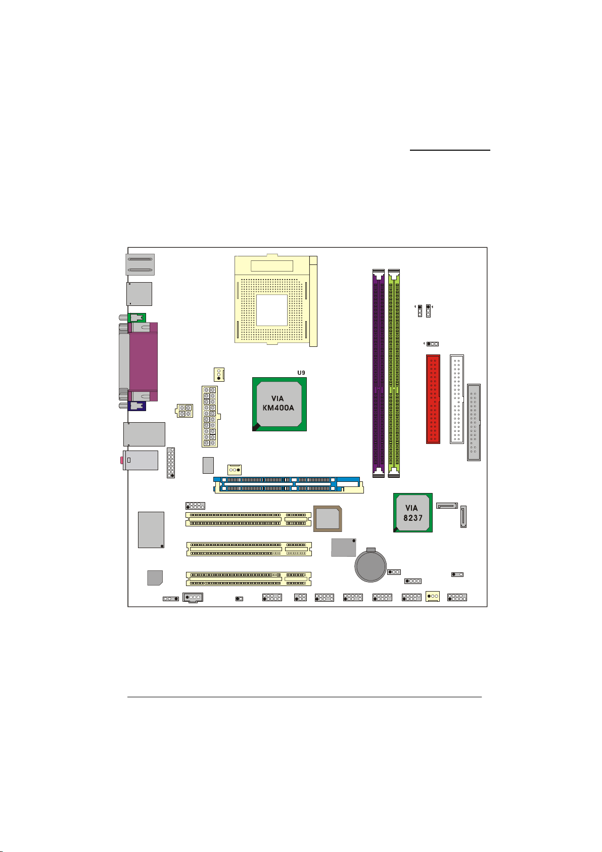
Configuration
Layout of KM400A PRO-1394
KB/MS
Socket 462
USB
U3
KM400A Series
USB/LAN
SOUND1
U16
Winbond
W83697HF
U19
Audio
Codec
PRT/COM/VGA
ATX_PWR
ATX _12 V
T
R
O
P
E
M
A
1
2
G
COM2
2
1
CD-IN
SPDIF
1
1
CPUFAN
U11
VT6103
9
PCI1
PCI2
PCI3
1
AUXFAN
1
CASE OPEN
1
FRONT AUDIO
2
1
AGP
10
9
JP6
JP5
JP4
IDE1
IDE2
FDC
BIOS
ROM
DIMM1
5
1
U
U18
DIMM2
1
4
U
SATA2
SATA1
VT6307
1
BAT1
JP1
1
2
6
1
5
IrDA
2
2
1
1
1394CN1
2
2
10
10
1
1
9
9
1394CN2
10
10
2
1
9
9
USB1
10
2
1
9
SPEAKER
USB2
1
10
9
CHASFAN
PWRLED
1
SW/LED
2 10
1
9
6
Page 11
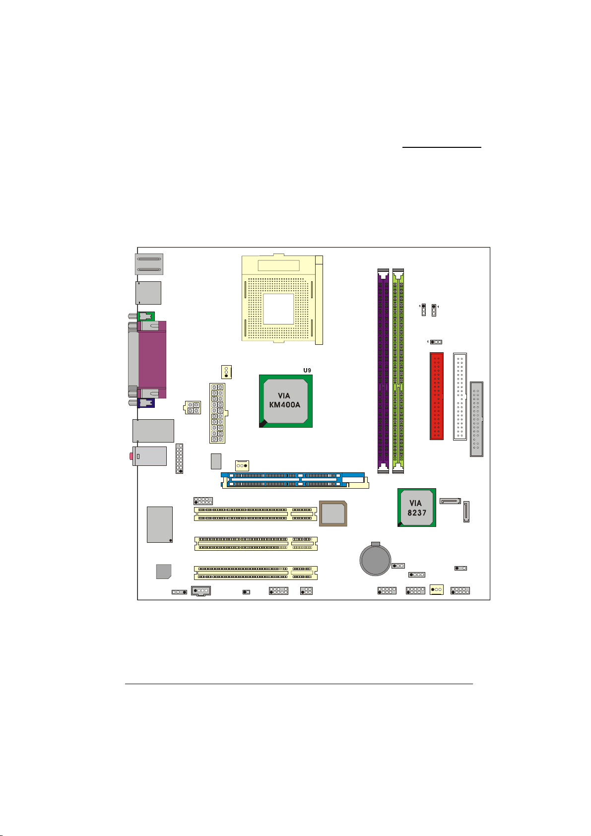
A
Layout of KM400A PRO
KB/MS
Socket 462
USB
U3
KM400A Series
USB
SOUND1
U16
Winbond
W83697HF
U19
Codec
PRT/COM/VGA
ATX_PWR
TX_12V
T
R
O
P
E
M
A
1
2
G
Audio
SPDIF
1
1
COM2
2
1
CD-IN
CPUFAN
U11
VT6103
9
1
AUXFAN
PCI1
PCI2
PCI3
1
CASE OPEN
1
FRONT AUDIO
JP5
JP6
JP4
IDE1
IDE2
FDC
AGP
5
U
1
BIOS
ROM
2
1
2
10
62
1
9
5
IrDA
DIMM1
BAT1
1
USB1
1
JP1
10
9
DIMM2
1
SPEAKER
2
1
USB2
1
4
U
1
10
9
CHASFAN
SATA 2
PWRLED
SW/LED
2 10
1
SATA1
1
9
7
Page 12
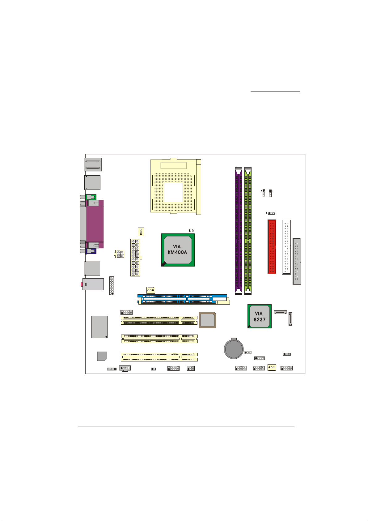
A
Layout of KM400A
KB/MS
USB
Socket 462
U3
KM400A Series
USB
SOUND1
U16
Winbond
W83697HF
U19
Codec
PRT/COM/VGA
ATX_PWR
TX_12V
T
R
O
P
E
M
A
1
2
G
Audio
SPDIF
1
1
COM2
2
1
CD-IN
CPUFAN
1
AUXFAN
9
PCI1
PCI2
PCI3
1
1
CASE OPEN
FRONT AUDIO
2
1
AGP
5
U
1
BIOS
ROM
BAT1
2
10
62
1
9
5
IrDA
JP5
JP6
JP4
IDE1
IDE2
FDC
DIMM1
1
USB1
1
JP1
10
9
DIMM2
1
SPEAKER
2
1
USB2
1
4
U
1
10
9
CHASFAN
SATA 2
PWRLED
SW/LED
2 10
1
SATA1
1
9
8
Page 13
p
KM400A Series
Hardware Installation
This section will assist you in quickly installing your system hardware. Wear a wrist ground strap
before handling components. Electrostatic discharge may damage your system components.
CPU Processor Installation
This mainboard supports AMD® processors using a Socket A. Before building your system, we
suggest you visit the AMD
http://www.amd.com
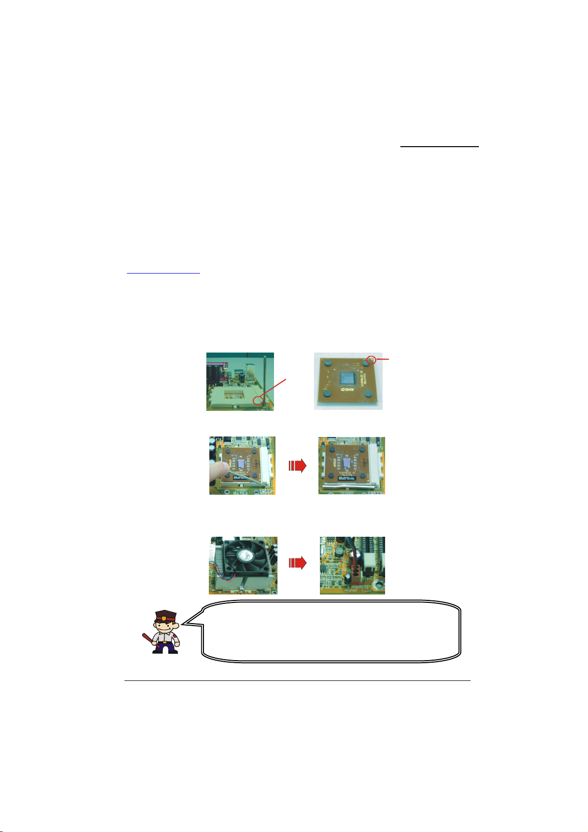
CPU Socket A Configuration Steps:
1. Locate the CPU socket on your mainboard and nudge the lever away from the socket. Then lift
the lever to a 90-degree angle.
2. On the socket, locate the corner that has the pin-1 receptor. This corner will be near to the end of
the lever. Match the corner on the CPU with the pin-1 receptor on the socket and lower the CPU
onto the socket. The bottom of the CPU should be flush with the face of the socket.
3. Lower the lever until it snaps back into position. This will lock down the CPU.
4. Smear thermal grease on top of the CPU. Lower the CPU fan onto the CPU and use the clasps on
the fan to attach it to the socket. Finally, extend the power cable from the fan and insert it onto the
CPUFAN adapter.
®
website and review the processor installation procedures.
Corner
Pin-1
receptor
Attention: Before starting the system
Please check the installation completely before starting the
system. Verify that the heatsink is properly installed and make
sure the CPU fan is working. Overheating can damage the CPU
and other sensitive com
onents.
9
Page 14
t
KM400A Series
FAN Headers
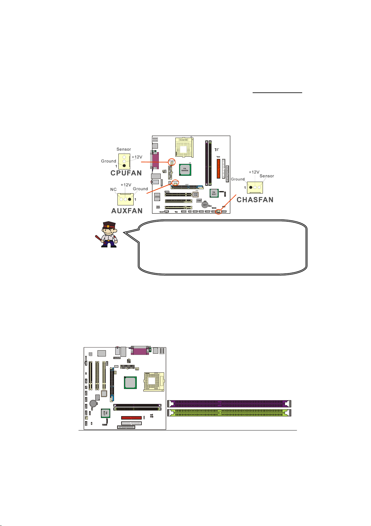
Three power headers are available for cooling fans, which play an important role in maintaining the
ambient temperature in your system.
Attention
This system has a BIOS configuration feature that issues a warning
(during POST) when the CPU fan is not plugged in or is no
functioning. In order to make use of this feature. You must make sure
that the CPU power cable is attached specifically to the “CPUFAN”
header. The BIOS configuration option is described in the “Hardware
Monitor” section of the BIOS Setup Utility Chapter.
Memory Installation
The mainboard contains 2 sockets, which use 184 pin DDR SDRAM with a total memory capacity of
up to 2 GB. You can install unbuffered & non-ECC DDR400/ 333/ 266/ 200 (PC3200/ 2700/ 2100/
1600) DDR SDRAM.
The KM400A Series supports 64 bit channels memory bus with a total memory capacity of up to 2
GB.
W83697HF
Winbond
Codec
Audio
1
1
1
1
210
9
1526
192
192
10
10
19210
19210
2
1
10
9
1
2
10
9
192
10
BAT1
1
1
1
2
1
1
2
9
1
BIOS
ROM
VT6307
DIMM1
DIMM2
1
VIA
KM400A
Socket462
U3
DIMM1
DIMM2
10
Page 15
f
t
KM400A Series
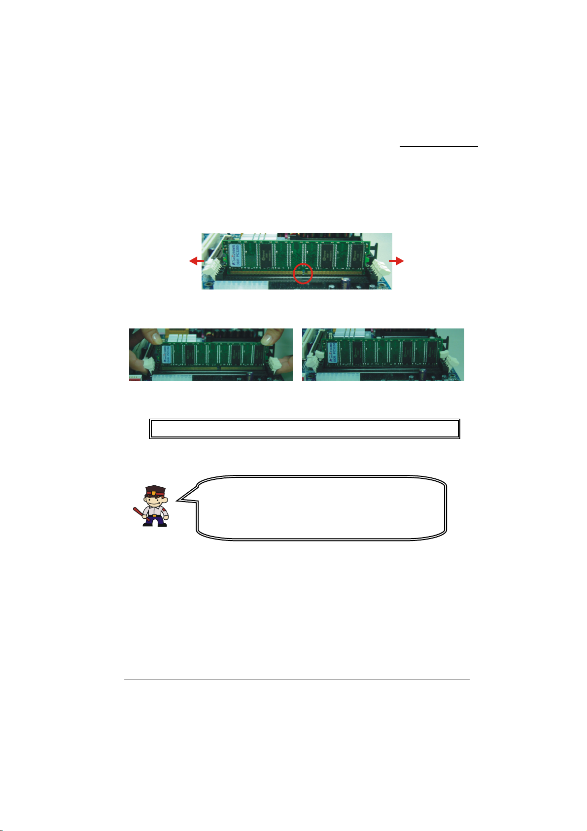
RAM Module Installation:
1. Pull the white plastic tabs on each side of the slot away from the slot.
2. Match the notch on the button of the RAM module with the corresponding pattern in the DIMM
slot. This ensures that the module is inserted properly.
3. Lower the RAM module into the DIMM Slot and press firmly using both thumbs until the module
snaps into place.
4. Repeat steps 1、2 and 3 for the remaining RAM modules.
* The pictures above are for reference only and may vary slightly for your mainboard.
Before Overclocking
Please make sure your system components are capable o
overclocking. If you are not familiar with the overclocking, we
strongly recommend that you to set the clock to the defaul
settings.
11
Page 16
p
KM400A Series
Back Panel Configuration
PS/2
Mouse
USB
PS/2
Keyboard
(Print Port)
Parallel Port
COM1
VGA
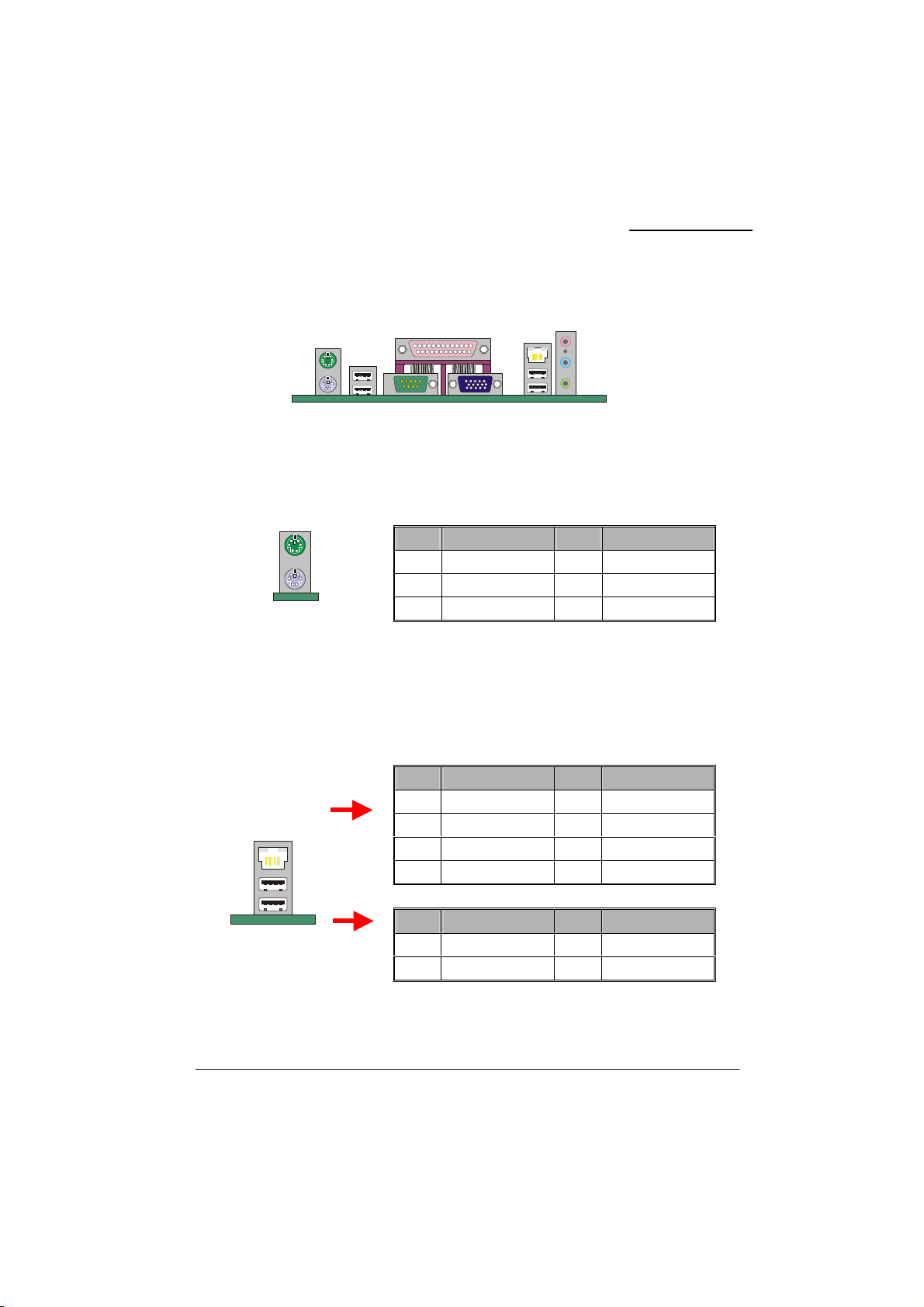
PS/2 Mouse & PS/2 Keyboard Connectors: KB/MS
This mainboard provides a standard PS/2 mouse connector and PS/2 Keyboard connector. The pin
assignments are described below:
PS/2 Mouse
PS/2 Keyboard
Pin Assignment Pin Assignment
1 Data 4 +5 V (fused)
2 No connect 5 Clock
3 Ground 6 No connect
USB & LAN Connectors: USB/(LAN=>optional)
There are 4 USB connectors on the back panel. These USB connectors are used to attach to USB
devices such as: keyboards, mice and other USB devices. You can plug the USB devices directly into
this connector. The KM400A PRO-1394/ KM400A PRO also provides a LAN port. You can plug
LAN devices directly into this connector.
(Optional)
LAN
USB
Pin Assignment Pin Assignment
1 TX+ 5 NC
2 TX- 6 RX-
3 RX+ 7 NC
4 NC 8 NC
Pin Assignment Pin Assignment
1/5 +5 V (fused) 3/7 USBP0+/P1+
2/6 USBP0-/P1- 4/8 Ground
(Optiona l)
LAN
Port
USB
Mic In
Line In
eaker Out
S
12
Page 17
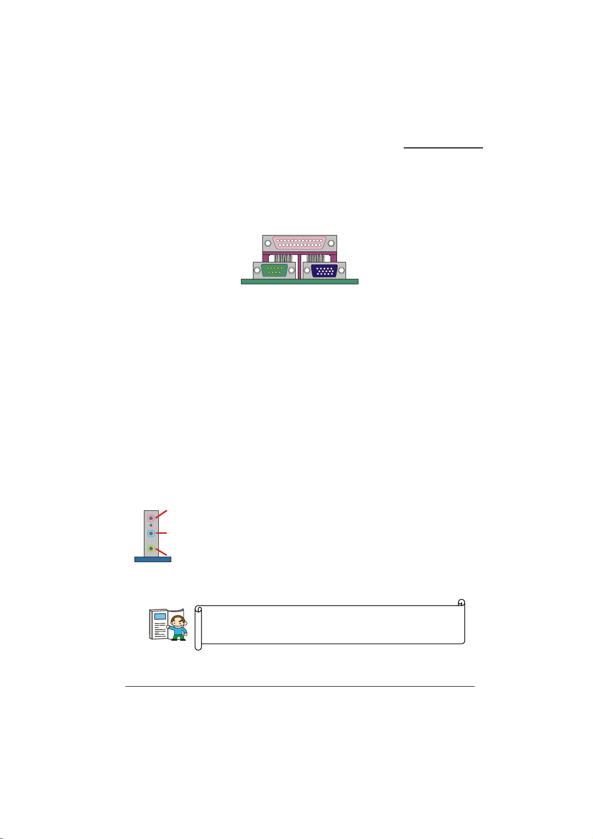
n
KM400A Series
Serial and Parallel Interface Ports
The mainboard comes equipped with one serial port, one parallel port and one VGA port on the back
panel. These interface ports will be explained below.
Parallel Interface Port: PRT
The parallel port on your system has a 25-pin, DB25 connector and is used to interface with parallel
printers and other devices using a parallel interface.
The Serial Interface: COM1
The serial interface port is sometimes referred to as an RS-232 port or an asynchronous
communication port. Mice, modems and other peripheral devices can be connected to a serial port.
Video Graphics Array Conn.: VGA
The KM400A Series has built in video facilities. Your monitor attaches directly to the VGA
connector on this mainboard.
Printer Port
COM1
VGA
Audio Port Connectors
Mic-i
(Subwoofer/Center out)
Line-in
(Rear Speaker out)
Speaker-out
(Front Speaker out)
This mainboard supports Super 5.1 Channel Audio effects which turns
your standard Speaker Out, Lin In, Mic In audio connectors into a 6
channel audio system. See Appendix I for more information.
Speaker Out is used to connect to speakers or
headphones. If the Super 5.1 driver is enabled the
Speaker Out becomes the Front Speaker.
Line In can be connected to an external CD player,
Tape player or other audio devices for audio input.
If the Super 5.1 driver is enabled Line In becomes
the Rear Speaker.
is used to connect to a microphone. If the
Mic In
Super 5.1 driver is enabled the Mic In becomes the
Subwoofer/ Center out.
13
Page 18
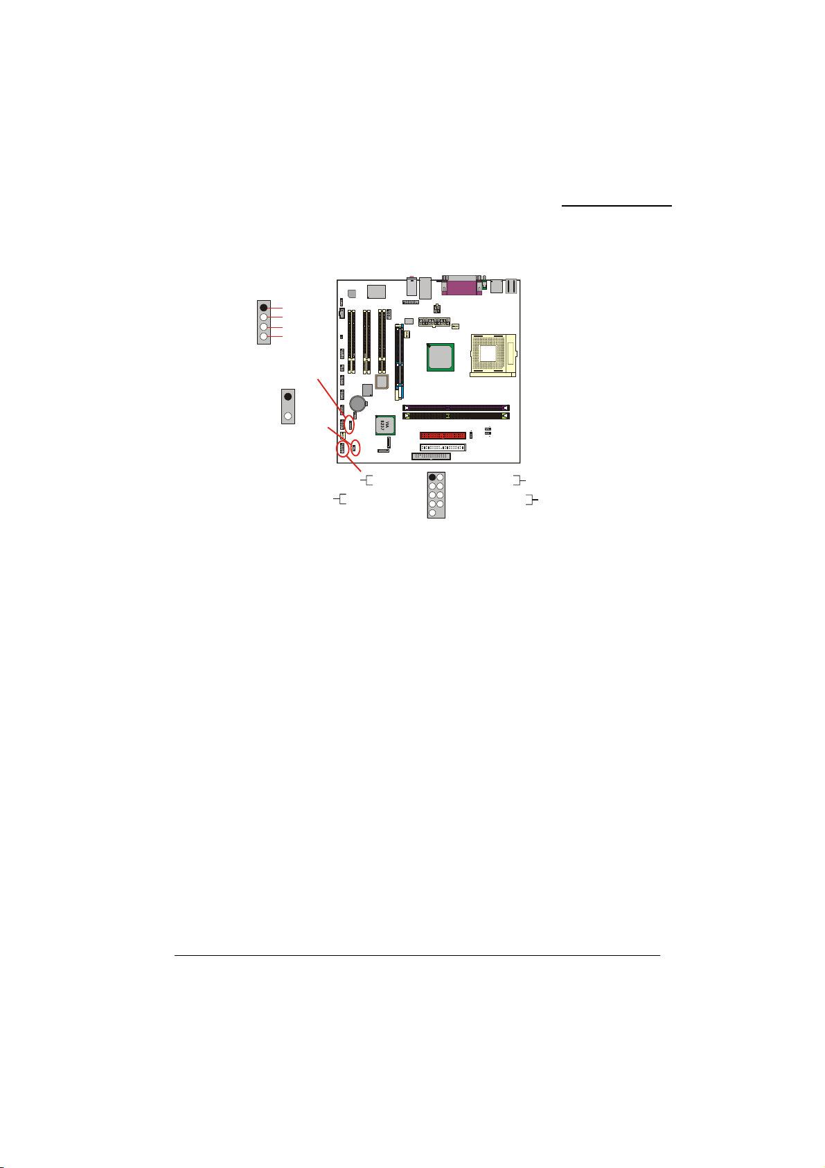
/
KM400A Series
Front Panel Indicator:
PC_BEEP
1
NC
Ground
4
+5V
SPEAKER
PWRLED
1
+
2
-
3
Hard Driver
LED
Reset
Button
W83697HF
Winbond
Codec
Audio
1
1
1
19210
1526
1
1
2
2
BIOS
ROM
VT6307
10
10
9
9
19210
19210
BAT1
2
1
1
10
9
1
2
SPEAKER
1
10
9
192 10
PWRLED
SW
1
LED
HD LED (+) Power LED (+)
HD LED (-)
Reset Control (-)
Reset Control (+)
SW/LED、PWRLED、SPEAKER
2
1
192
NC
1
9210
1
VIA
KM400A
Power LED (-)
Power Button (+)
Power Button (-)
NC
Socket 46 2
Power
LED
Power-on
Button
1
SW/LED
HD LED (Hard Drive LED Connector)
This connector can be attached to an LED on the front panel of a computer case. The LED will
flicker during disk activity. This disk activity only applies to those IDE drives directly attached to the
system board.
RST (Reset Button)
This connector can be attached to a momentary SPST switch. This switch is normally left open.
When closed it will cause the mainboard to reset and run the POST (Power On Self Test).
PWR-LED (2-Pin Power LED Connector)
This connector can be attached to an LED on the front panel of a computer case. The LED will
illuminate while the computer is powered on.
PWR ON (Power Button)
This connector can be attached to a front panel power switch. The switch must pull the Power Button
pin to ground for at least 50 ms to signal the power supply to switch on or off (the time required is
due to internal debounce circuitry on the system board). At least two seconds must pass before the
power supply will recognize another on/off signal.
PWRLED (3-Pin Power LED )
If there is a 3-pin power LED cable on the front panel of a computer case. You can attach it to the
3-pin power LED connector.
SPEAKER (Speaker Header)
A front panel speaker can be connected to this connector. When you boot your computer, the speaker
sounds a short “beep”. If there is something wrong during the Power On Self-Test, the speaker
sounds “irregular beep” to warning you.
14
Page 19
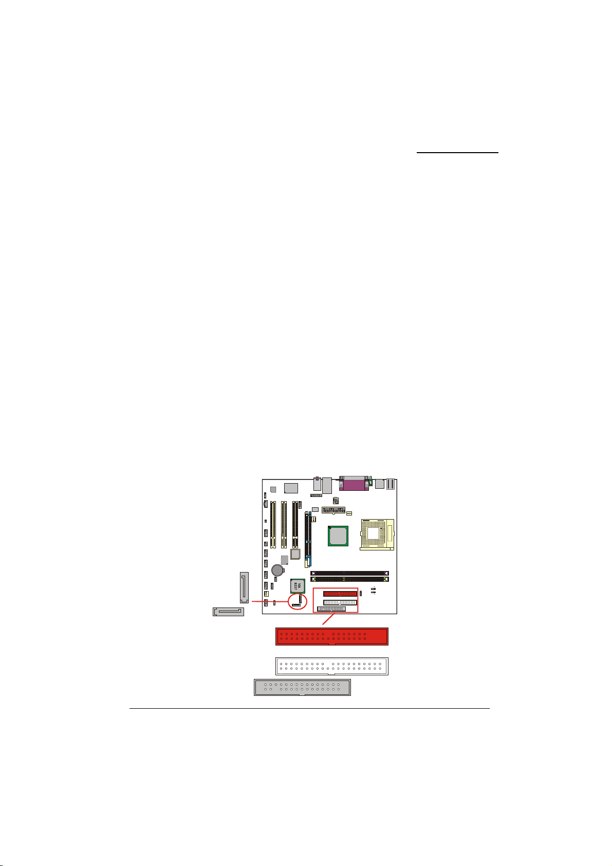
KM400A Series
Connectors
Floppy Disk Connector: FDC
This mainboard provides a standard floppy disk connector (FDC) that supports 360K, 720K, 1.2M,
1.44M and 2.88M floppy diskettes. This connector supports the floppy drive ribbon cables provided
in the packaging.
Hard Disk Connectors: IDE1-2、SATA1-2
This mainboard has a 32-bit Enhanced PCI IDE Controller that supports Ultra 6-0/ DMA 2-0 and
PIO 4-0 modes, Ultra ATA 133/ 100/ 66/ 33. It has two IDE connectors, IDE1 (primary) and IDE2
(secondary). The KM400A Series also has a Serial ATA controller and provides two serial ATA
connectors.
IDE1 (Primary IDE Connector)
You can connect up to two hard drives to IDE1. If you attach two drives, you must use a ribbon cable
with three connectors. You must also configure one drive as the master and one drive as the slave,
using the jumpers located on each drive.
IDE2 (Secondary IDE Connector)
The IDE2 controller can also support a Master and a Slave drive. The configuration is similar to
IDE1. The second drive on this controller must be set to slave mode.
SATA1/ SATA2
The SATA connectors support transfer rate to 150 MB/s and SATA RAID 0 or 1 mode. The
connectors only can connect one serial ATA hard disk device each. (for more detail pleas refer to the
Appendix II.)
W83697HF
Winbond
Codec
Audio
SATA2
SATA1
1
1
1
1
2
10
9
152
6
19210
19210 2
19210192
10
1
10
9
1
2
10
9
192 10
BAT1
1
1
1
VT6307
IDE2
2
1
192
1
BIOS
ROM
1
VIA
KM400A
IDE2
IDE1
FDC
Socket 462
IDE1
F
D
C
15
Page 20
A
A
A
A
KM400A Series
Headers & Jumpers & Switch
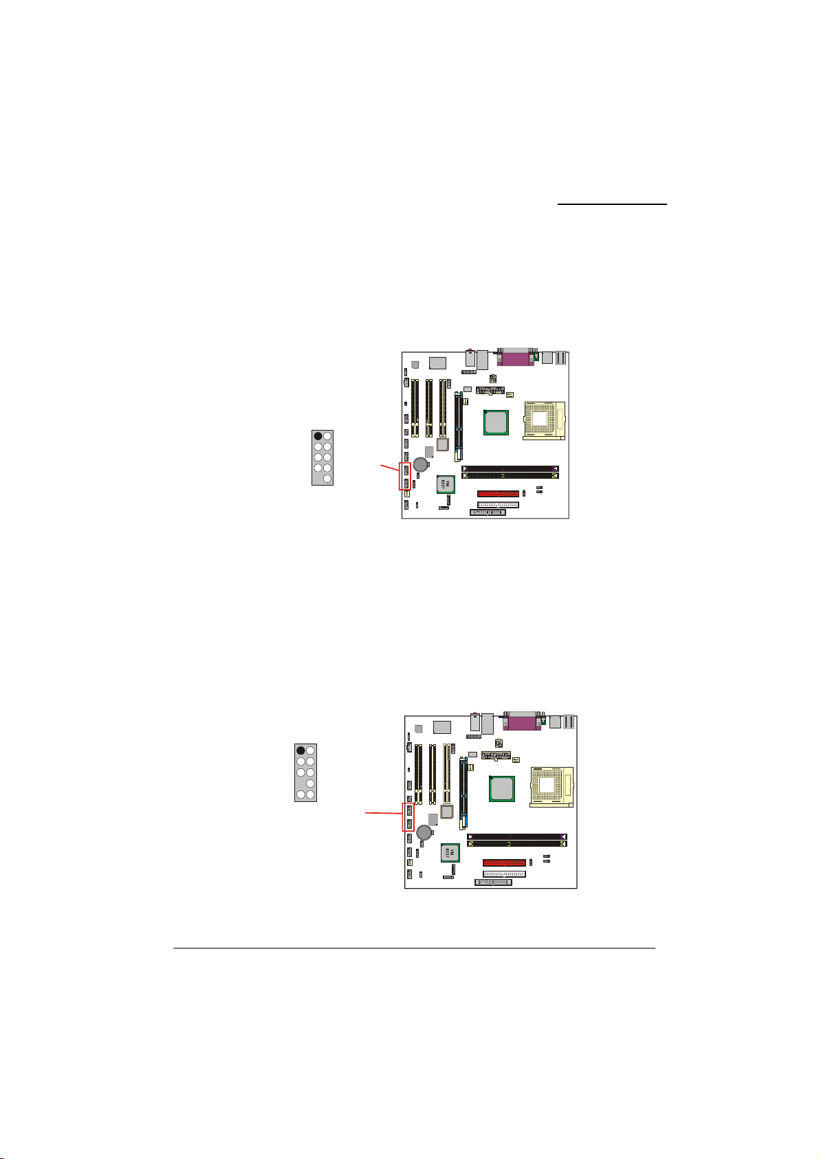
Front USB Headers: USB1/ USB2
You can connect the USB Bracket to the USB1/ USB2 header. There will be USB ports on the USB
Bracket which means you can connect USB device to the USB port. The mainboard supports up to 8
USB devices including 4 on the back panel.
192
5VSB5VSB
DATA_B-DATA_ADATA_B+DATA_A+
GroundGround
NCNC
10
USB1/2
USB Bracket (optional)
You can connect the USB bracket to the USB1/ USB2 header.
* If you are using USB 2.0 devices with Windows
the USB 2.0 driver from the Microsoft
®
website.
IEEE 1394 Headers: 1394 CN1/ 1394 CN2
The IEEE 1394 high-speed serial bus provides enhanced PC connectivity for consumer electronics
audio/video (A/V) appliances, storage peripherals, other PCs, and portable devices. The KM400A
PRO supports up to two IEEE 1394 devices. You can connect the IEEE 1394 bracket (optional) to
the 1394 CN1/ 1394 CN2 header.
1394CN1/2
192
TPAMTPAP
GroundGround
TPBMTPBP
Chasis GroundNC
NCPWR
10
W83697HF
Winbond
Codec
udio
USB1
USB2
9
1
1
9
9
1
9
1
9
192 10
1
1
1
1
2
10
152
6
2
2
10
10
19210192
10
2
10
2
10
1
1
1
1
9
1526
1
1
1394CN1
9
9
19210
19210
1394CN2
1
9
1
9
192
B
T1
1
1
1
Codec
udio
210
2
2
10
10
2
10
2
1
10
1
10
2
1
M
E
A
G
O
P
R
T
192
1
1
KM400A
VIA
BIOS
ROM
VT6307
®
XP or Windows® 2000, you will need to install
W83697HF
Winbond
2
1
192
1
1
KM400A
VIA
BIOS
ROM
VT6307
B
T1
1
Socket 46 2
Socket462
16
Page 21
A
A
A
A
KM400A Series
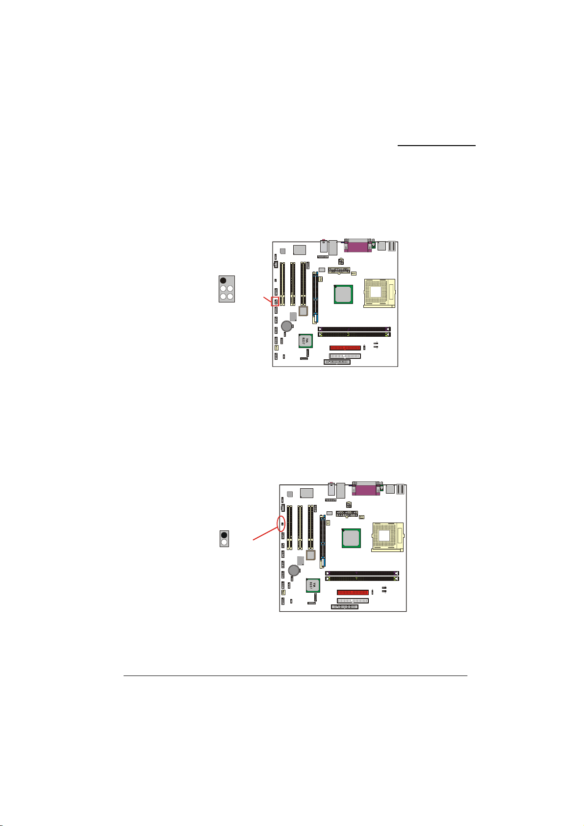
Infrared Header: IrDA
This IrDA connector can be configured to support wireless infrared and is used to attach to an
infrared sensing device. After the IrDA interface is configured, you can use this connector for
connectionless data transfer to and from portable devices such as laptops and PDAs.
IR_TX
152
NCNC
Ground+5V
IR_RX
6
IrDA
W83697HF
Winbond
U19
Codec
Audio
1
1
1
1
2
10
9
152
IrD
6
1
1
210
210
9
9
19210192
10
B
2
1
T1
1
10
9
1
2
1
10
9
192 10
1
2
1
192
1
BIOS
ROM
VT6307
1
KM400A
VIA
Socket462
Case Open Warning Jumper: CASE OPEN
This connector is used to notify the user when the computer case has been previously opened. To
configure this functionality, your computer case must be equipped with a “ case open” cable which
you need to attach to the CASE OPEN jumper. Also, you must enable CASE OPEN warning
functionality in the BIOS setup utility. When your computer case is opened, your system will display
alert messages upon boot up. Note that your computer case must be equipped with a “case open”
cable.
W83697HF
Caseop-
Ground
1
2
CASE OPEN
Winbond
Codec
Audio
1
1
C
1
SEOPEN
1
2
10
9
152
6
1
1
210
210
9
9
19210192
10
B
2
1
T1
1
10
9
1
2
1
10
9
192 10
1
2
1
192
1
BIOS
ROM
VT6307
1
KM400A
VIA
Socket 462
17
Page 22
V
A
KM400A Series
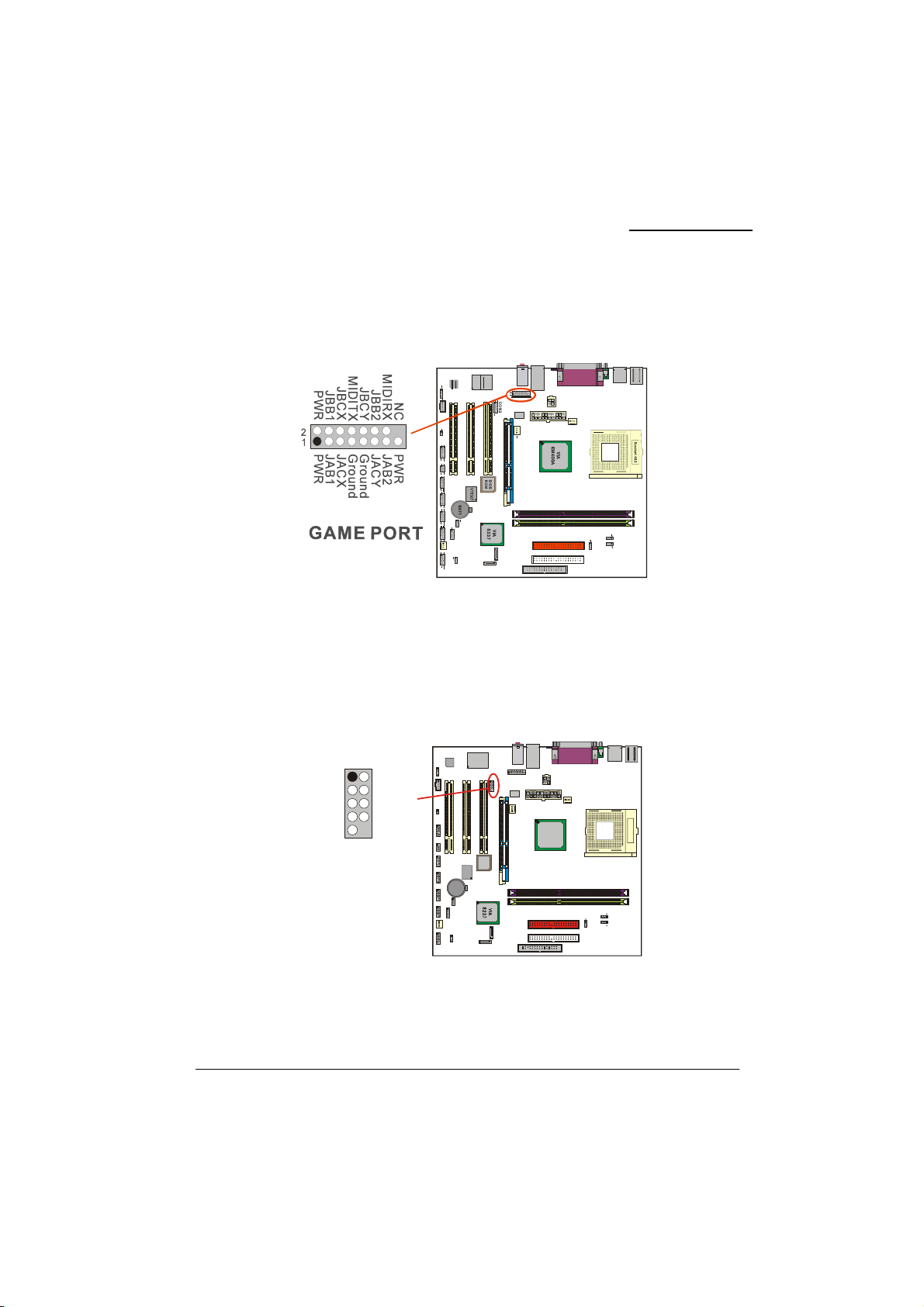
Game Port Header: GAME PORT
This mainboard supports a front game port header. To use this header you can install a COM port &
Game port bracket (optional) with a Game port wire extending to this header. You can then attach
gaming devices to the game port on the bracket.
Front Serial Port Header: COM2
This mainboard supports a front serial header. To use this header, you can install a back panel bracket
(optional) with a wire extending to this header. You can then attach your serial device to the serial
port on the bracket.
SOUT
Ground
RINGW
192
RTS-
COM2
SIN-DCDDTRDS6CTSNC
10
W83697HF
Winbond
Codec
Audio
1
1
1
1
2
10
9
152
6
1
1
210
210 2
9
9
19210192
10
B
1
T1
1
10
9
1
2
1
10
9
192 10
1
2
1
192
COM2
1
BIOS
ROM
VT6307
1
KM400A
IA
Socket462
18
Page 23
KM400A Series
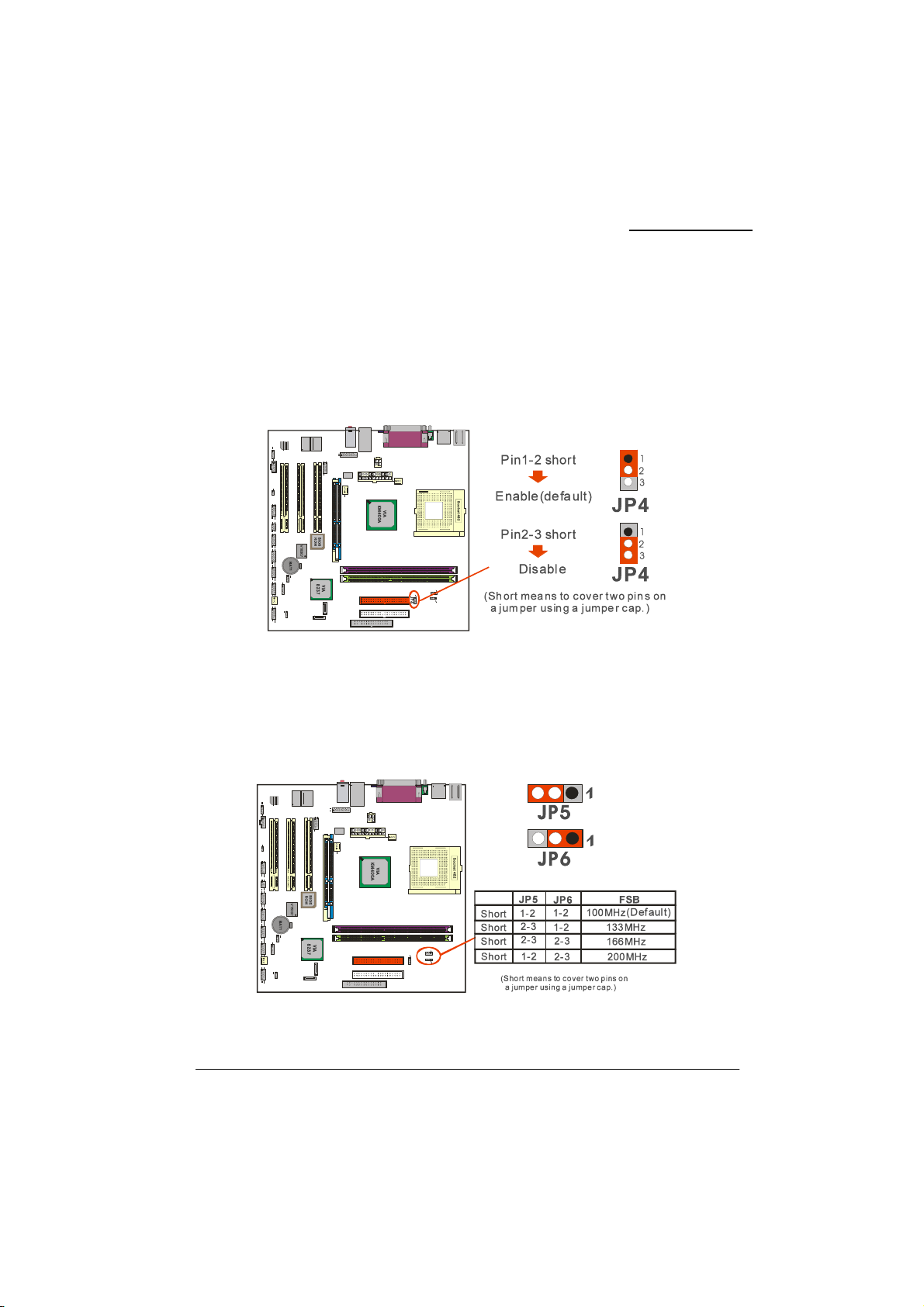
OTP (Over Temperature Protection) Jumper: JP4
The mainboard supports a special design for CPU Over Temperature Protection. If this function is
“Enabled” and the CPU temperature rises above the normal range, the system will automatically shut
down and you have to unplug the ATX_PWR connector. Remove and reinstall the CPU heat sink
also check to make sure the CPU fan is working properly.
*OTP is only functional when using an Athlon XP
TM
or BartonTM CPU.
CPU Clock Select Jumper: JP5、JP6
Use the jumper “JP5、JP6” to select the CPU Clock. If you are installing a CPU that has a 133 MHz
CPU clock, you also have to set the “FSB Frequency” to 133 MHz in the BIOS Setup Utility.
19
Page 24
A
A
KM400A Series
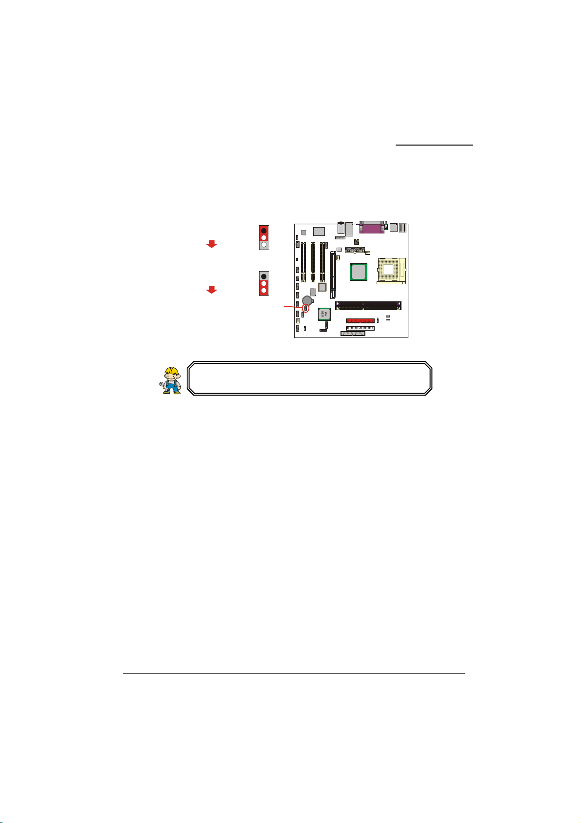
Clear CMOS Jumper: JP1
The “Clear CMOS” jumper is used when you cannot boot your system due to some CMOS
configuration problem such as a forgotten password. This jumper allows you to reset the CMOS
configurations, and then reconfigure.
Pin1-2 short
Normal (default)
Pin2-3 short
Clear CMOS data
(Short means to cover two pins on
a jumper using a jumper cap.)
JP1
JP1
1
2
3
1
2
3
The following procedures are for resetting the BIOS password. It is
important to follow these instructions closely.
1. Turn off your system and disconnect the AC power cable.
2. Set JP1 to OFF (2-3 Closed).
3. Wait several seconds.
4. Set JP1 to ON (1-2 closed).
5. Connect the AC power cable and turn on your system.
6. Reset your desired password or clear CMOS data.
W83697HF
Winbond
Codec
udio
1
1
1
1
2
10
9
152
6
1
1
2
2
10
10
9
9
19210192
10
2
1
JP1
10
9
1
2
1
10
9
192 10
1
2
1
192
1
1
KM400A
VIA
BIOS
ROM
VT6307
B
T1
1
Socket 462
20
Page 25
p
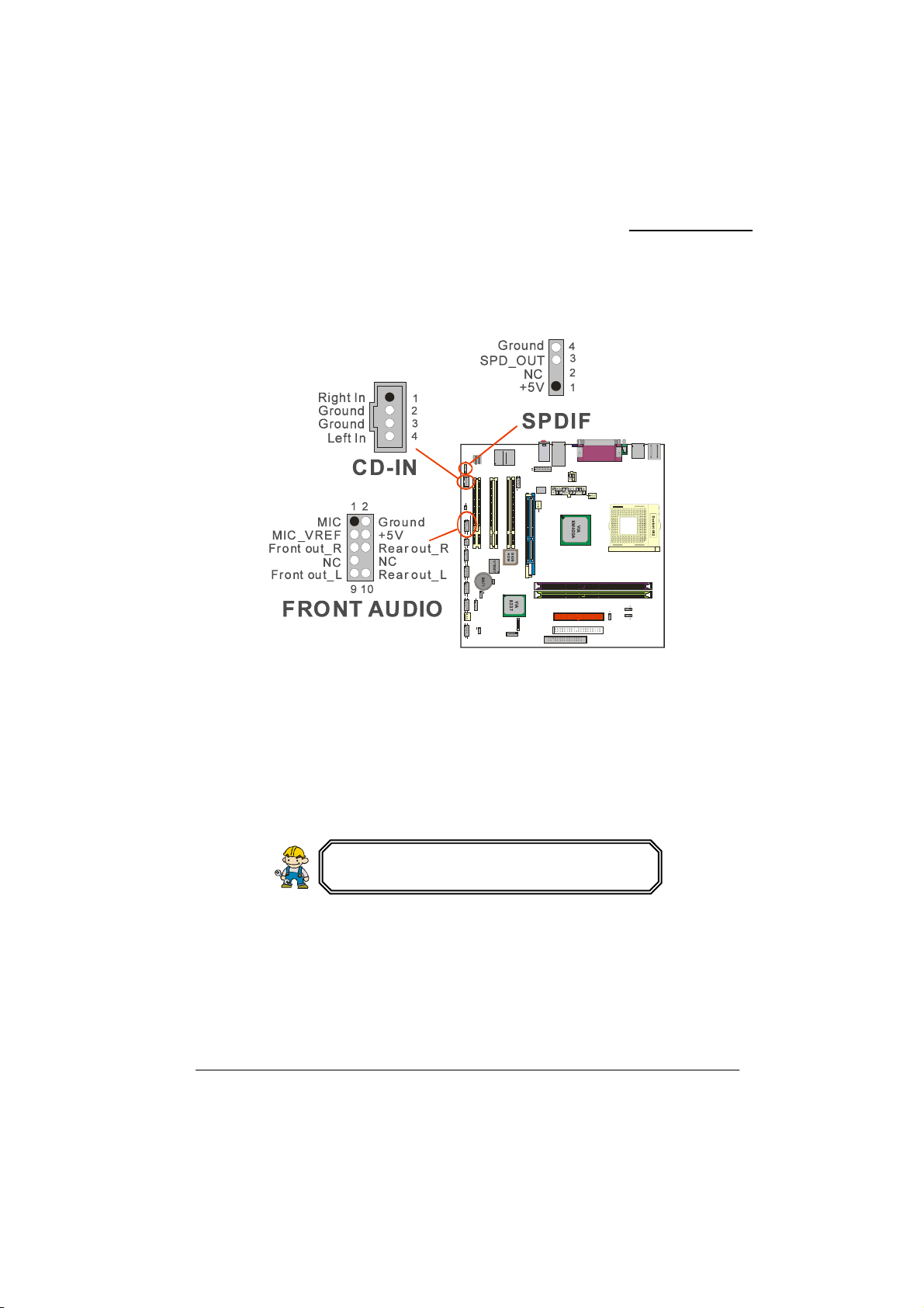
Audio Connectors
This mainboard provides three connectors as part of its audio Subsystem.
KM400A Series
CD-ROM Audio-In Header: CD-IN
This header is used to connect to a CD-ROM / DVD audio cable.
Front Panel Audio Header: FRONT AUDIO
If your computer case has been designed with embedded audio equipment. You can attach these
components to the FRONT_AUDIO panel of the mainboard. First remove the jumper caps covering
the FRONT_AUDIO pins. Use pins 1, 3 to connect to the case microphone. Use pins 9,5 to connect
to the earphone. If you do not intend to use the FRONT_AUDIO panel, do not remove the jumper
caps. The front panel audio effect and the back panel audio effect cannot simultaneous function.
If the jumper caps are in place, jumper cap 1 is on pin 5,
in 6 and jumper cap 2 is on pin 9, pin 10.
S/PDIF Header: SPDIF
S/PDIF (Sony/Philips Digital Interface) is an audio transfer file format, which provides high quality
audio using optical fiber and digital signal. This mainboard is capable of delivering audio output
through the SPDIF header. The SPDIF devices that are sending information from this header must be
compliant for optimal effect.
21
Page 26
A
A
X
A
X
V
A
A
KM400A Series
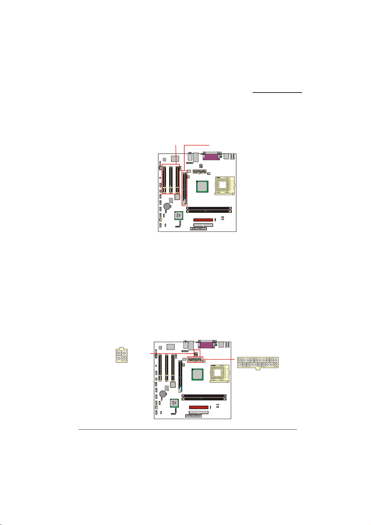
Slots
The slots in this mainboard are designed for expansion cards used to complement and enhance the
functionality of the mainboard.
AGP Slot: AGP
The KM400A Series is equipped with an Accelerated Graphics Port (AGP) that supports 4X/ 8X
(1.5V) AGP cards only.
PCI Slots: PCI1-3
The KM400A Series is equipped with 3 standard PCI slots. PCI stands for Peripheral Component
Interconnect and is a bus standard for expansion cards. This PCI slot is designated as 32 bit.
PCI Slots
W83697HF
Winbond
Codec
Audio
1
1
1
1
210
9
1526
192
192
10
10
19210
19210
2
1
10
9
1
2
10
9
192 10
BAT1
1
1
1
2
1
1
2
9
1
BIOS
ROM
VT6307
1
VIA
KM400A
GP Slot
Socket462
Power Supply Attachments
ATX Power Connector: ATX_PWR、ATX_12V
This mainboard requires two ATX power connectors; a 20-pin connector and a 4-pin connector. Your
power supply must have both connectors. Attach the 4-pin connector first, then attach the 20-pin
connector. Make sure the connectors are secure before applying power.
+12V
Ground
+12V
Ground
ATX_12V
W83697HF
Winbond
Codec
Audio
1
1
1
1
2
10
9
152
6
19210
19210 2
19210192
10
B
1
T1
1
10
9
1
2
1
10
9
192 10
1
2
1
T
1
2
9
BIOS
ROM
VT6307
_12
T
_PWR
1
1
KM400A
VIA
Socket462
+5.0V
Gruond
+3.3V+3.3V
+3.3V-12V
Ground
PS_ON
TX_PWR
22
Ground
5.0V_SB
Ground
+5.0V
PW_OK
+12V
+5.0V
+5.0V
Ground
+5.0V
Ground
Ground
Page 27

KM400A Series
Chapter 2. BIOS Setup
Introduction
This section describes PHOENIX-AWARD™ BIOS Setup program which resides in the ROM BIOS
firmware. The Setup program allows users to modify the basic system configuration. The
configuration information is then saved to CMOS RAM where the data is sustained by Li-battery
after power-down.
The BIOS provides critical low-level support for standard devices such as disk drives, serial ports
and parallel ports. As well, the BIOS controls the first stage of the boot process, loading and
executing the operating system.
The PHOENIX-AWARD
standard BIOS. This means that it supports the BIOS of AMD
This version of the PHOENIX-AWARD™ BIOS includes additional features such as virus and
password protection as well as special configurations for fine-tuning the system chipset. The defaults
for the BIOS values contained in this document may vary slightly with the version installed in your
system. (When you boot up the computer, the BIOS version will appear at up-left of the POST
screen.)
TM
BIOS installed in Flash ROM is a custom version of an industry
®
based processors.
Plug and Play Support
This PHOENIX-AWARD™ BIOS supports the Plug and Play Version 1.0A specification as well as
ESCD (Extended System Configuration Data) write.
APM Support
This PHOENIX-AWARD™ BIOS supports Version 1.1 & 1.2 of the Advanced Power Management
(APM) specification. These features include system sleep and suspend modes in addition to hard disk
and monitor sleep modes. Power management features are implemented using the System
Management Interrupt (SMI).
PCI Bus Support
This PHOENIX-AWARD™ BIOS also supports Version 2.2 of the Intel PCI (Peripheral Component
Interconnect) local bus specification.
23
Page 28

KM400A Series
Supported CPUs
This PHOENIX-AWARD™ BIOS supports the AMD® Athlon XPTM, AthlonTM, DuronTM, and
TM
Barton
CPUs.
Key Function
In general, you can use the arrow keys to highlight items, press <Enter> to select, use the <PgUp>
and <PgDn> keys to change entries, press <F1> for help and press <Esc> to quit. The following table
provides more detail about how to navigate within the BIOS Setup program.
Keystroke Function
Up arrow
Down arrow
Left arrow
Right arrow
Esc
Move Enter
PgUp key
PgDn key
+ Key
- Key
F1 key
F5 key
F6 key
F7 key
F10 key
Move to the item on the left (menu bar)
Move to the item on the right (menu bar)
Main Menu: Quit without saving changes
Submenus: Exit Current page to the next higher level
Increase the numeric value or enter changes
Decrease the numeric value or enter changes
Increase the numeric value or enter changes
Decrease the numeric value or enter changes
General help on Setup navigation keys
Load the fail-safe defaults from BIOS default table
Move to previous item
Move to next item
menu
Move to the item you desire
Load previous values from CMOS
Load the optimized defaults
Save all the CMOS changes and exit
24
Page 29
KM400A Series
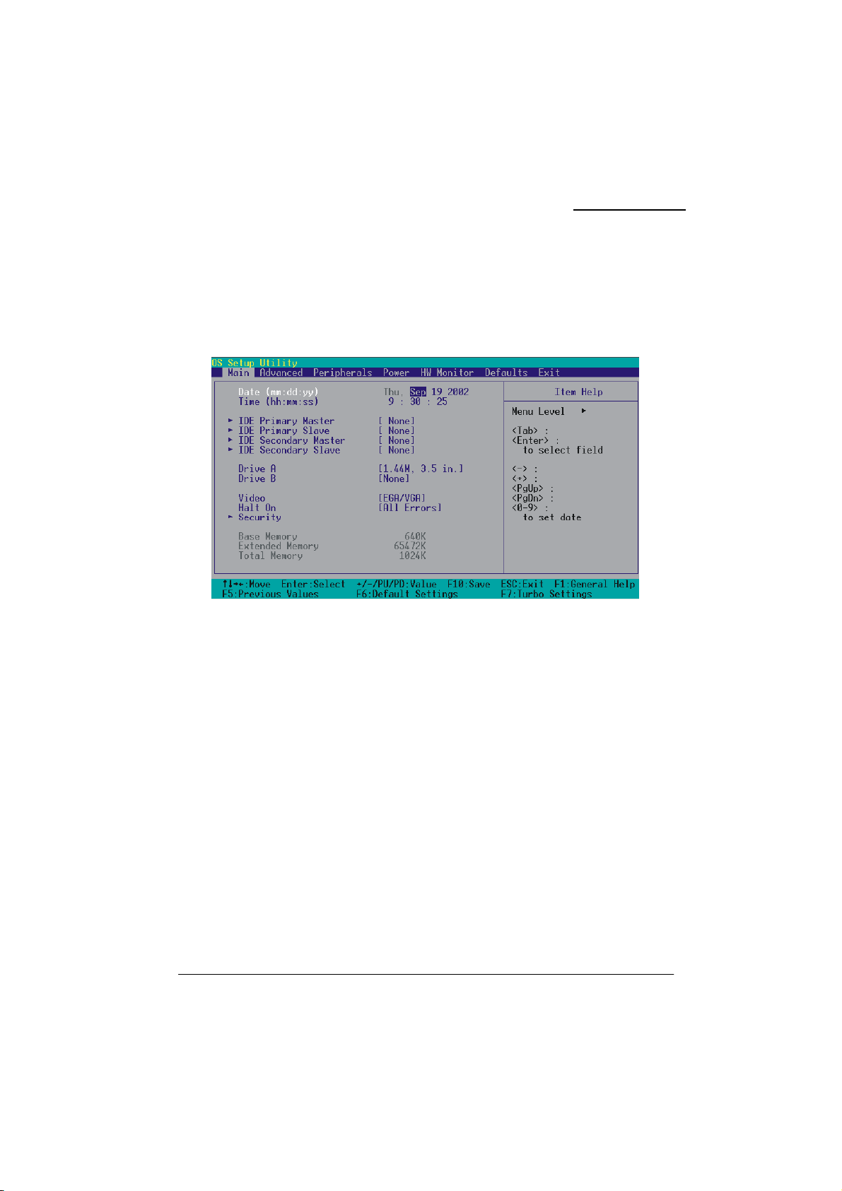
Main Menu
When you enter the PHOENIX-AWARD™ BIOS Utility, the Main Menu will appear on the screen.
The Main menu allows you to select from several configuration options. Use the left/right arrow keys
to select a particular configuration screen from the top menu bar or use the down arrow key to access
and configure the information below.
25
Page 30

Main Menu Setup Configuration Options
Item Options Description
Date
Time
IDE Primary
Master
IDE Primary
Slave
IDE Secondary
Master
IDE Secondary
Slave
Drive A
Drive B
Video
Halt On
Security
Base Memory
Extended
Memory
Total Memory
mm dd yyyy
Hh: mm: ss Set the current time of the system.
Options contained in
sub menu.
Options contained in
sub menu.
Options contained in
sub menu.
Options contained in
sub menu.
360K, 5.25 in
1.2M, 5.25 in
720K, 3.5 in
1.44M, 3.5in
2.88M, 3.5 in
None
EGA/VGA
CGA 40
CGA 80
MONO
All Errors
No Errors
All, but Keyboard
All, but Diskette
All, but Disk/ Key
Options contained in
sub menu.
N/A
N/A
N/A Displays the total memory available in the system.
Set the system date. Note that the ‘Day’ automatically
changes when you set the date.
Press <Enter> to enter the sub menu.
Press <Enter> to enter the sub menu.
Press <Enter> to enter the sub menu.
Press <Enter> to enter the sub menu.
Select the type of floppy disk drive installed in your system.
Select the default video device.
Select the situation in which you want the BIOS to stop the
POST process and notify you.
Press <Enter> to enter the sub menu.
Displays the amount of
conventional memory
detected during boot up.
Displays the amount of
extended memory detected during boot up.
KM400A Series
26
Page 31
KM400A Series
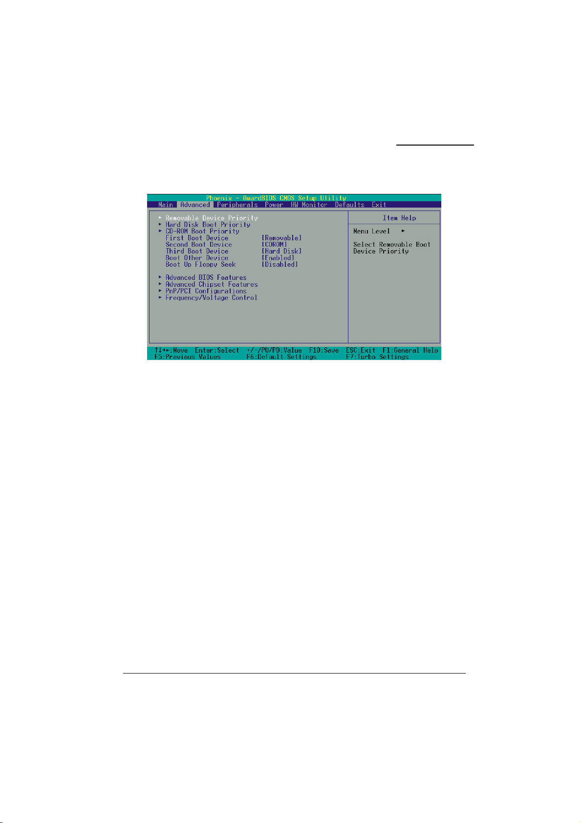
Advanced BIOS Features
Removable Device Priority
Select removable device priority. Just like floppy, LS120, ZIP-100, USB-FDD and USB-ZIP.
Hard Disk Boot Priority
Select hard disk boot priority.
CD-ROM Boot Priority
Select CD-ROM boot priority.
First /Second/Third Boot Device
Select the order in which devices will be searched in order to find a boot device.
Options: Removable (default for first boot device)、CD ROM (default for second boot device)、Hard
Disk (default for third boot device)、Disabled
Boot Other Device
Set to “Enabled” allows the system to try to boot from other devices if the system fails to boot from
the 1st/ 2nd/ 3rd boot devices. Options: Enabled (default)、Disabled
27
Page 32

KM400A Series
Boot Up Floppy Seek
When Enabled, the BIOS tests (seeks) floppy drives to determine whether they have 40 or 80 tracks.
Only 360-KB floppy drives have 40 tracks. Drives with 720KB, 1.2MB, and 1.44MB capacity all
have 80 tracks. Because very few modern PCs have 40-track floppy drives, we recommend that you
set this field to “Disabled”.
Options: Enabled、Disabled (default)
Advanced BIOS Features
CPU Internal Cache
Make CPU internal cache active or inactive. System performance may degrade if you disable this
item. Options: Enabled (default)、Disable.
External Cache
This option allows you to enable or disable “Level 2” secondary cache on the CPU to enhance
performance. Options: Enabled (default)、Disabled
CPU L2 Cache ECC Checking
Make CPU L2 cache ECC function active or inactive. Options: Disabled、Enabled (default)
Quick Power On Self Test
Allow the system to skip certain tests while booting. This will speed up the boot process.
Options: Enabled (default)、Disabled.
Swap Floppy Drive
If the system has two floppy drives, choose “Enabled” to assign physical drive B to logical drive A
and vice-versa. Options: Disabled (default)、Enabled.
Boot Up NumLock Status
Selects the power on state for NumLock.
Options: On (default) Numpad keys are number keys.
Off Numpad keys are arrow keys.
Typematic Rate Setting
When “Enabled”, the “typematic rate” and “typematic delay” can be configured. Typematic Rate
determines the keystroke repeat rate used by the keyboard controller..
Options: Disabled (default)、Enabled
28
Page 33

KM400A Series
Typematic Rate (Chars/Sec)
The rate at which a character repeats when you hold down a key.
Options: 6 (default)、8、10、12、15、20、24、30
Typematic Delay (Msec)
The delay before keystrokes begin to repeat. Options: 250 (default)、500、750、1000
APIC Mode
By enabling this option, “MPS version control for OS” can be configured.
Options: Disabled、Enabled (default)
MPS Version Control For OS
The 1.1 version is the older version that supports 8 more IRQs in the Windows NT environment.
Choose the new 1.4 version for Windows 2000 and Windows XP.
Options: 1.4 (default)、1.1
OS Select For DRAM > 64MB
Select “OS2” only if you are running the OS/2 operating system with greater than 64 MB of RAM.
Options: Non-OS2 (default)、OS2
HDD S.M.A.R.T. Capability
Self Monitoring Analysis and Reporting Technology is a technology that enables a PC to attempt to
predict the possible failure of storage drives. Options: Disabled (default)、Enabled
Small LOGO (EPA) Show
This item allows you to show or hide the small LOGO EPA.
Options: Disabled (default)、Enabled
Advanced Chipset Features
DRAM Clock/ Drive Control
Press <Enter> to enter next page for DRAM Clock/ Drive Control settings.
DRAM Timing
This item determines DRAM clock/ timing using the manual configuration.
Options: Manual、Auto (default)
29
Page 34

KM400A Series
DRAM CAS Latency
This item determines CAS Latency. When synchronous DRAM is installed, the number of clock
cycles of CAS latency depends on the DRAM timing. Do not reset this field from the default value
specified by the system designer. Options: 1.5、2、2.5、3
Precharge to Active (Trp)
You can set the time to precharge. Options: 5T、2T、3T、4T
Active to Precharge (Tras)
This item allows you to select DRAM Active to Precharge Delay.
Options: 7T、6T、8T、9T
Active to CMD (Trcd)
Select the DRAM delay time when being read. Options: 5T、2T、3T、4T
DRAM Command Rate
This item determines DRAM Command Rate.
Options: 2T Command (default)、1T Command
AGP & P2P Bridge Control
Press <Enter> to enter next page for AGP & P2P Bridge Control.
AGP Aperture Size
Select the size of the Accelerated Graphics Port (AGP) aperture. The aperture is a portion of the PCI
memory address range dedicated for graphics memory address space. Host cycles that hit the aperture
range are forwarded to the AGP without any translation.
Options: 1G、512M、256M、128M (default)、64M、32M、16M、8M、4M
(The 1G and 512M options only appear when you install 8X AGP card.)
AGP Mode
This item allows you to select the AGP Mode. Options: 1X、2X、4X (default)
(*If you install the 8X AGP card, then the item will be lock in 8X option.)
AGP Driving Control
By choosing “Auto” the system BIOS will automatically set the AGP output buffer drive strength. By
choosing “Manual”, it allows user to set the AGP output buffer driver strength.
AGP Driving Value
While the AGP Driving Control option is set to “Manual”, it allows the user to set AGP Driving
Value. Options: DA (default)、00~FF
30
Page 35

KM400A Series
AGP Fast Write
The AGP Fast Write technology allows the CPU to write directly to the graphics card bypassing the
system AGP 4X speed. Choose “Enable” only when you used with AGP card support.
Options: Disabled (default)、Enabled
AGP Master 1 WS Write
When enabled, writes to the AGP (Accelerated Graphics Port) are executed with one wait state.
Options: Disabled (default)、Enabled
AGP Master 1 WS Read
When enabled, reads from AGP (Accelerated Graphics Port) are executed with one wait state.
Options: Disabled (default)、Enabled
AGP3.0 Calibration cycle
This item will appear when you install the 8X VGA card. Options: Enabled (default)、Disabled
VGA Share Memory Size
Select the size of the onboard VGA port. Options: Disabled、16M、32M、64M(default)
CPU & PCI Bus Control
Press <Enter> to enter the next page for CPU & PCI Bus Control
PCI 1/2 Master 0 WS Write
When enabled, writes to the PCI bus are executed with zero-wait states.
Options: Enabled (default)、Disabled
PCI Delay Transaction
The chipset has an embedded 32-bit post write buffer to support delay transactions cycles. Select
Enabled to comply with PCI specifications. Options: Disabled、Enabled (default)
Memory Hole
When enabled, you can reserve an area of system memory for ISA adapter ROM. When this area is
reserved, it cannot be cached. Refer to the user documentation of the peripheral you are installing for
more information. Options: Disabled (default)、15M-16M
System BIOS Cacheable
When enabled, accesses to system BIOS ROM addressed at F0000H-FFFFFH are cached, provided
that the cache controller is enabled. Options: Enabled、Disabled (default)
31
Page 36

KM400A Series
Video RAM Cacheable
Select “Enabled” to allow caching of the video RAM which may improve performance. If any other
program writes to this memory area, a system error may result. Options: Enabled、Disabled (default)
PnP/PCI Configurations
PNP OS Installed
When set to “YES”, BIOS will only initialize the PnP cards used for the boot sequence (VGA, IDE,
SCSI). The rest of the cards will be initialized by the PnP operating system like Windows
set to “NO”, BIOS will initialize all the PnP cards. For non-PnP operating systems (DOS, Netware),
this option must be set to “NO”.
Options: No (default)、Yes
Reset Configuration Data
Select “Enabled” to reset the Extended System Configuration Data (ESCD) if you have installed a
new add-on card and the system reconfiguration has caused such a serious conflict that the OS cannot
boot. Options: Disabled (default)、Enabled
Resources Controlled By
BIOS can automatically configure all the boot and Plug and Play compatible devices. If you choose
Auto, you will not be able to manually assign IRQ DMA and memory base address fields, since
BIOS automatically assigns them. Options: Auto <ESCD> (default)、Manual
IRQ Resources
When resources are controlled manually, you can assign each system interrupt a type, depending on
the type of device using the interrupt. This is only configurable when “Resources Controlled By” is
set to “Manual”.
IRQ-3 assigned to: PCI device
IRQ-4 assigned to: PCI device
IRQ-5 assigned to: PCI device
IRQ-7 assigned to: PCI device
IRQ-9 assigned to: PCI device
IRQ-10 assigned to: PCI device
IRQ-11 assigned to: PCI device
IRQ-12 assigned to: PCI device
IRQ-14 assigned to: PCI device
IRQ-15 assigned to: PCI device
®
95. When
32
Page 37

KM400A Series
PCI / VGA Palette Snoop
Some graphic controllers that are not VGA compatible take the output from a VGA controller and
map it to their display as a way to provide boot information and VGA compatibility.
Options: Disabled (default)、Enabled
PCI Latency Timer (CLK)
This item allows you to set up the PCI Latency Time (0-255). If you select the “32” it will optimize
PCI speeds. Options: 0-255、32 (default)
Frequency/Voltage Control
CPU Speed Detected
This item displays the CPU speed information detected by the system.
Spread Spectrum
The Spread Spectrum function can reduce the EMI (Electromagnetic Interference) generated.
Options: -1.50%、-1.00%、-0.70%、+/-0.25%、+/-0.50% (default)、+/-0.35%、+/-0.75
CPU Clock
This item displays the CPU Host Clock. You can set it from 100 to 233. The default depends on your
CPU frequency. If you over-clock the CPU clock ratio and the DDR:CPU ratio items can be adjusted.
Default: By CPU speed
AGP/PCI Frequency (MHz)
This item displays the AGP/PCI Frequency.
DDR:CPU Ratio
This item allows you to adjust the DDR: CPU Clock Ratio. You can adjust this option to match the
DDR module you have installed.
If the CPU host frequency is 100 Options: 2.66X (default)
If the CPU host frequency is 133 Options: By SPD(default)、2.00X、2.50X、3.00X
If the CPU host frequency is 166 Options: By SPD(default)、1.60X、2.00X、2.40X
If the CPU host frequency is 200 Options: By SPD(default)、1.33X、1.66X、2.00X
DDR Speed (strobe/sec)
This item displays the DDR Speed. (CPU Host frequency * DDR:CPU Ratio)
33
Page 38
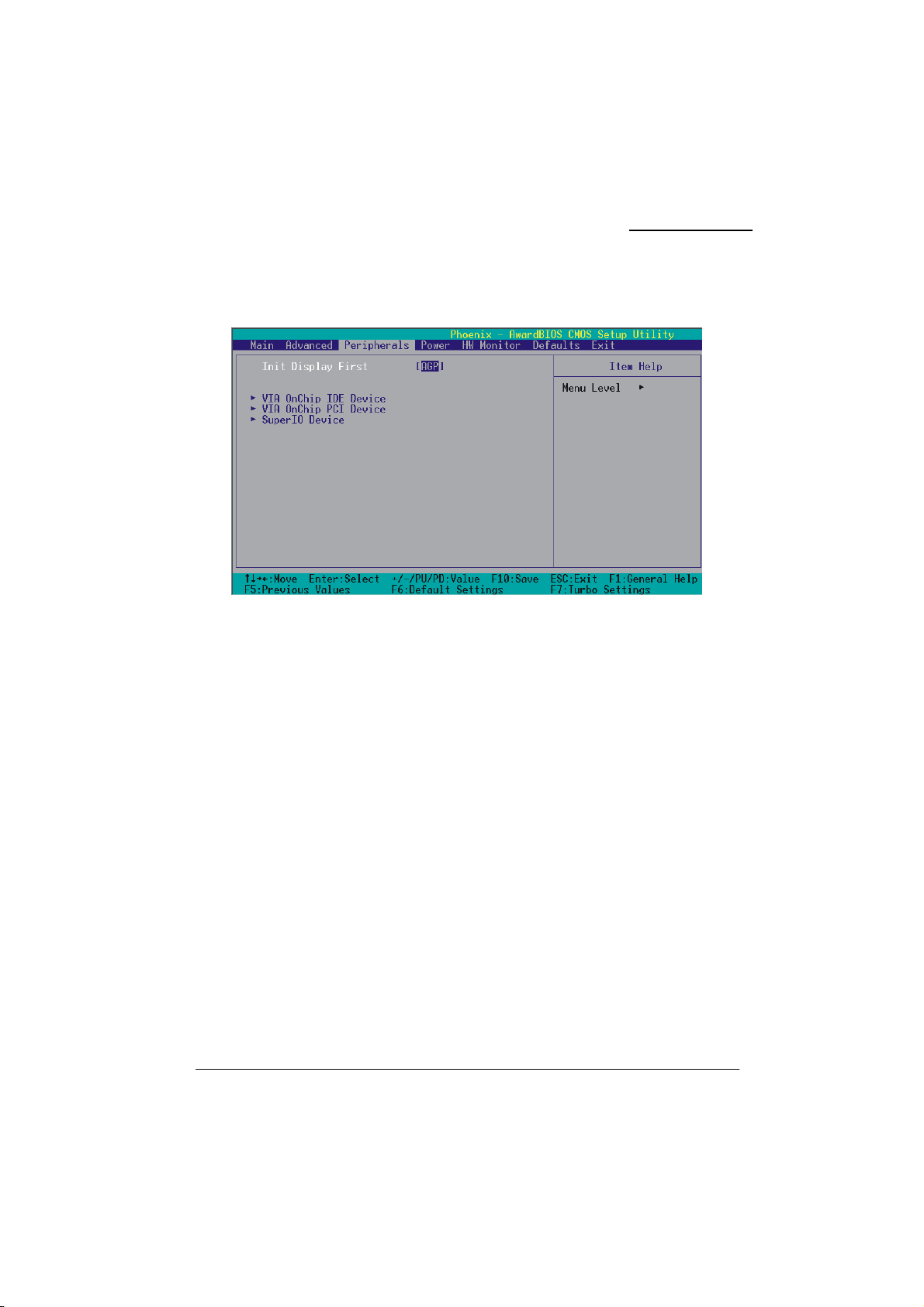
Integrated Peripherals
KM400A Series
Init Display First
With systems that have multiple video cards, this option determines whether the primary display uses
a PCI slot or an AGP slot. Options: AGP、PIC Slot (default)
VIA OnChip IDE Device
If you highlight the “VIA OnChip IDE Device” label and then press the enter key, it will take you to
a submenu with the following options:
OnChip SATA
This item allows you to enable or disable on-chip SATA function.
Options: Enabled (default)、Disabled
SATA Mode
This item allows you to select the SATA Mode.
Options: RAID (default)、IDE
IDE Channel0/1
The mainboard chipset contains a PCI IDE interface with support for two IDE channels. Select
“Enabled” to activate the first and/or second IDE interface. Select “Disabled” to deactivate an
interface if you are going to install a primary and/or secondary add-in IDE interface. Options:
Enabled (default)、Disabled
34
Page 39

KM400A Series
IDE Prefetch Mode
The “onboard” IDE drive interfaces supports IDE prefetching for faster drive access. If you install a
primary and/or secondary add-in IDE interface, set this option to “Disabled” if the interface does not
support prefetching. Options: Enabled (default)、Disabled
Primary/Secondary/Master/Slave PIO
The IDE PIO (Programmed Input / Output) fields let you set a PIO mode (0-4) for each of the IDE
devices that the onboard IDE interface supports. Modes 0 to 4 will increase performance
incrementally. In Auto mode, the system automatically determines the best mode for each device.
Options: Auto (default)、Mode0、Mode1、Mode2、Mode3、Mode4.
Primary / Secondary /Master / Slave UDMA
Ultra DMA/133 functionality can be implemented if it is supported by the IDE hard drives in your
system. As well, your operating environment requires a DMA driver (Windows 95 OSR2 or a third
party IDE bus master driver). If your hard drive and your system software both support Ultra
DMA/133, select “Auto” to enable BIOS support.
Options: Auto (default)、Disabled
IDE HDD Block Mode
Block mode is otherwise known as block transfer, multiple commands, or multiple sector read/write.
Select the “Enabled” option if your IDE hard drive supports block mode (most new drives do). The
system will automatically determine the optimal number of blocks to read and write per sector.
Options: Enabled (default)、Disabled
VIA OnChip PCI Device
If you highlight the “VIA OnChip PCI Device” label and then press the enter key, it will take you a
submenu with the following options:
AC’97 Audio
This option allows you to control the onboard AC’97 audio.
Options: Enabled (default)、Disabled
Onboard 1394 Device (only for KM400A PRO-1394)
This option allows you to control the onboard 1394 device.
Options: Enabled (default)、Disabled
Onboard LAN Device (for KM400A PRO-1394/ KM400A PRO)
This option allows you to control the onboard LAN device.
Options: Enabled (default)、Disabled
35
Page 40

KM400A Series
Onboard Lan Boot ROM
This item allows you to invoke the boot ROM of the onboard LAN chip.
Options: Disabled (default)、Enabled
USB Controller
This option should be enabled if your system has a USB port installed on the system board. You will
need to disable this feature if you add a higher performance controller.
Options: All Enabled (default)、All Disabled
OnChip EHCI Controller
This option should be enabled if your system has a USB 2.0 device installed on the system board.
You will need to disable this feature if you install a USB 1.1 device.
Options: Enabled (default)、Disabled
USB Device Support
Enables support for USB attached devices. Options: Disabled (default)、Enabled
Super IO Device
If you highlight the literal “Press Enter” next to the “Super IO Device” label and then press the enter
key, it will take you a submenu with the following options:
Onboard FDC Controller
Select Enabled if your system has a floppy disk controller (FDC) installed on the system board and
you wish to use it. If you install an add-in FDC or the system has no floppy drive, select “Disabled”
in this field. Options: Enabled (default)、Disabled
Onboard Serial Port 1
Select an address and corresponding interrupt for the first serial port.
Options: Disabled、 3F8/IRQ4 (default)、 2F8/IRQ3、 3E8/IRQ4、 2E8/IRQ3、 Auto
Onboard Serial Port 2
Select an address and corresponding interrupt for the second serial port.
Options: Disabled、2F8/IRQ3 (default)、3F8/IRQ4、3E8/IRQ4、2E8/IRQ3、Auto.
Onboard Parallel Port
This item allows you to determine the parallel port interrupt and address.
Options: 378/IRQ7 (default)、278/IRQ5、3BC/IRQ7、Disabled
36
Page 41

Parallel Port Mode
This option allows you to select an operating mode for the on board parallel port.
Options: ECP(default)
EPP Enhanced Parallel Port.
SPP Standard Printer Port.
ECP+EPP ECP & EPP mode.
Normal
Extended Capabilities Port.
EPP Mode Select
Select EPP port type 1.7 or 1.9. Options: EPP 1.7, EPP1.9(default).
ECP Mode Use DMA
Select a DMA Channel for the port. Options: 3 (default)、1
Game Port Address
Game Port I/O Address. Options: 201 (default)、209、Disabled
Midi Port Address
Midi Port Base I/O Address. Options: 330 (default)、300、290、Disabled
Midi Port IRQ
This determines the IRQ that Midi Port will use. Options: 5 (default)、7
KM400A Series
37
Page 42
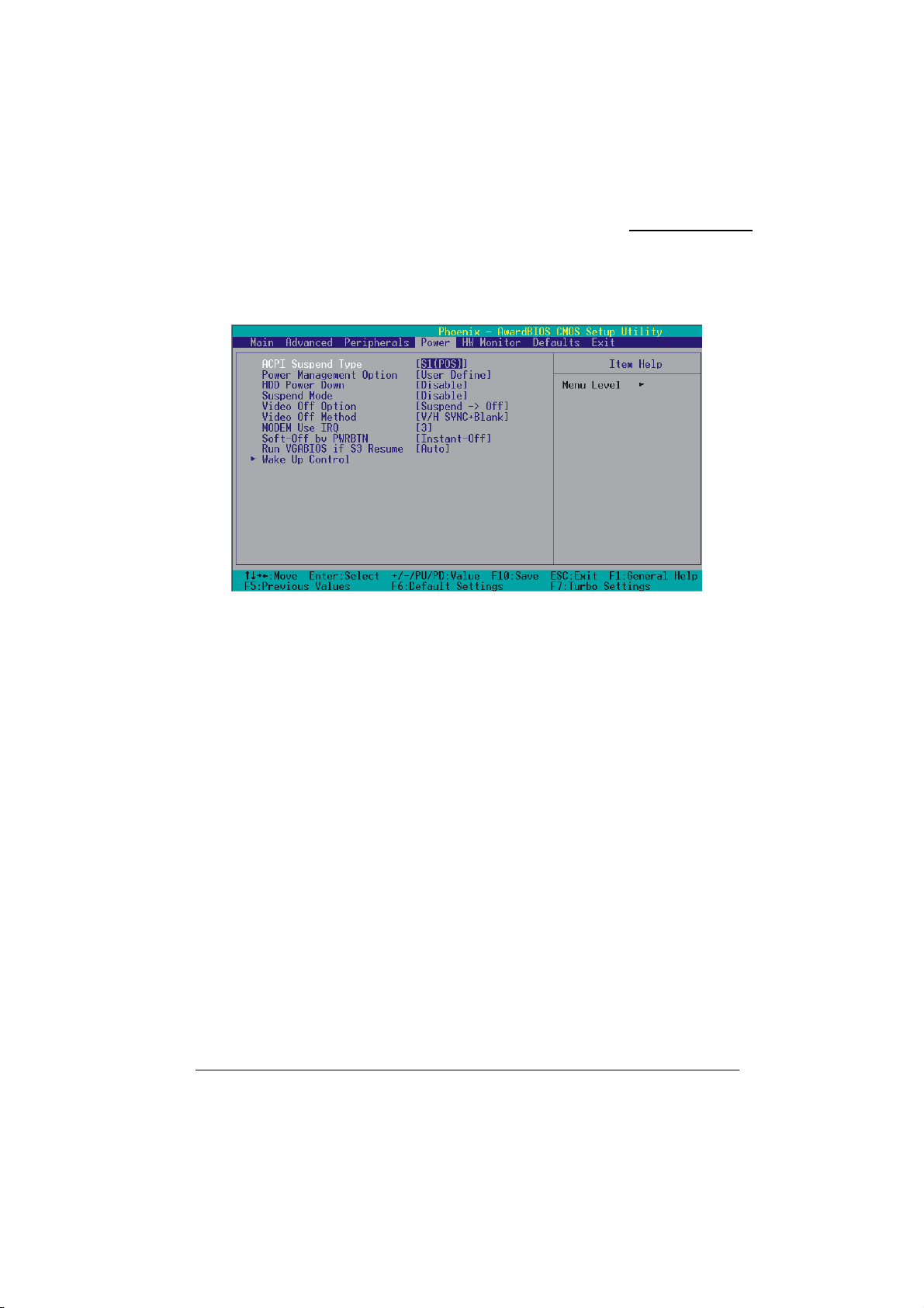
KM400A Series
Power Management
The Power Management Setup Menu allows you to configure your system to utilize energy
conservation features as well as power-up/ power-down options.
ACPI Suspend Type
The item allows you to select the suspend type using the ACPI operating system.
Options: S1 (POS) (default) Power on Suspend
S3 (STR) Suspend to RAM
S1 & S3 POS and STR
Power Management Option
There are three options of Power Management:
1. Min. Saving
Minimum power management
Suspend Mode = 1hour
HDD Power Down = 30 minutes
2. Max. Saving
Maximum power management (only available for sl CPUs).
Suspend Mode = 1 min.
HDD Power Down = 6 min.
38
Page 43

KM400A Series
3. User Defined (default)
Allows you to set each mode individually.
When this option is enabled, the “suspend mode” time is configurable from 1 minute to 1 hour. The
HDD Power Down, which ranges from 1 min. to 15 min. and includes a “disable” option.
Note: If you select Min. or Max. Power Saving modes, the “HDD Power Down” value and the
“Suspend Mode” value are both fixed.
HDD Power Down
When enabled, the hard disk drive will power down after a certain configurable period of system
inactivity. All other devices remain active.
Options: Disabled (default)、1 Min、2 Min、3 Min、4 Min、5 Min、6 Min、7 Min、8 Min、9 Min
10 Min、11 Min、12 Min、13 Min、14 Min、15Min
Suspend Mode
This item allows you to select the period of inactivity before the system is suspended or put into
suspend mode.
Options: Disabled(default)、1Min、2Min、4Min、6Min、8Min、10Min、20Min、30Min、40Min
1Hour
、
、
Video Off Option
This field determines when to activate the video off feature for monitor power management.
Options: Suspend→Off (default), Always On.
Video Off Method
This option determines the manner in which the monitor goes blank.
Options:
V/H SYNC+Blank(default) This selection will cause the system to turn off the vertical and
horizontal synchronization ports and write blanks to the video buffer.
Blank Screen This option only writes blanks to the video buffer.
DPMS Support Initial display power management signaling.
Modem Use IRQ
This determines the modem’s IRQ. Options: 3 (default)、4、5、7、9、10、11、NA.
39
Page 44

KM400A Series
Soft-Off by PWRBTN
Pressing the power button for more than 4 seconds forces the system to enter the
Soft-Off state when the system has “hung.” Options: Delay 4 Sec, Instant-Off (default).
Run VGABIOS if S3 Resume
Select whether you want to run VGABIOS when the system wakes up from the S3 resume function.
Options: Auto (default)、Yes、No
Wake Up Control
If you highlight the “Wake Up Control” label and then press the enter key, it will display a submenu
with the following options:
PWRON After PWR-Fail
This option determines whether you want to restart the system after a power failure. Select “On”, to
boot the system whether or not the system was on before power failure. Choose Former-Sts, to
restore the system to the status before the power failure.
Options: Off (default)、On
PS2KB Wake Up Select
Use this option to configure the PS2 keyboard Wake Up feature.
“Password”
from PS2 keyboard activity.
“Hot Key”
configure the hotkey.
PS2KB Wake Up from S3/S4/S5
This option is used when “PS2KB Wake Up Select” is configured as “HOT KEY”.
Options: Disable (default), Ctrl+F1(to F12), Power, Wake, Anykey.
Power Button Lock
This item allows you to lock the power button. Options: Enabled、Disabled (default)
USB Wake Up
This item allows you to select USB devices to awaken the system from suspend mode.
Options: Disabled (default)、Enabled
Use this selection to force the user to enter a password after the system awakens
Use PS2KB key to awake the system. See “PS2KB Wake Up from S3-S5” to
40
Page 45

KM400A Series
VGA
When set to “On”, any event occurring at a VGA Port will awaken a system which had been
previously powered down. Options: OFF (default)、On.
LPT & COM
When this option is set to On, any event occurring at a COM(serial)/LPT (printer) port will awaken a
system which has been suspended.
Options: LPT/COM (default)、COM、LPT、NONE
HDD & FDD
When set to “On”, any event occurring on a hard drive activity or a floppy drive activity will awaken
the system which had been previously suspended. Options: ON、OFF (default)
PCI Master
When set to “On”, you need a LAN add-on card which supports the power on function. It should also
support the wake-up on LAN jumper. Options: OFF (default)、ON
PCI PME Wake Up
When you select “Enabled”, a PME signal from any PCI card will awaken the system from suspend
mode. Options: Disabled (default)、Enabled
Ring Wake Up
This option allows you to awaken the system upon receiving an incoming call to a modem device.
Option: Disabled (default)、Enabled
RTC Wake Up
When “Enabled”, you can set the date and time at which the RTC (real-time clock) alarm awakens
the system from Suspend mode. Options: Enabled、Disabled (default)
Date (of Month)
You can choose which month the system will boot up. This field is only configurable when “RTC
Wake Up” is set to “Enabled”
Resume Time (hh: mm: ss)
You can choose the hour, minute and second the system will boot up. This field is only configurable
when “RTC Wake Up” is set to “Enabled”
41
Page 46

KM400A Series
IRQs Activity Monitoring
Press Enter to access a sub menu used to configure the different wake up events (i.e. wake on LPT &
COMM activity).
Primary INTR On
IRQ3 (COM2) Enabled
IRQ4 (COM1) Enabled
IRQ5 (LPT2) Enabled
IRQ6 (Floppy Disk) Enabled
IRQ7 (LPT1) Enabled
IRQ8 (RTC Alarm) Disabled
IRQ9 (IRQ2 Redir) Disabled
IRQ10 (Reserved) Disabled
IRQ11 (Reserved) Disabled
IRQ12 (PS/2 Mouse) Enabled
IRQ13 (Coprocessor) Disabled
IRQ14 (Hard Disk) Enabled
IRQ15 (Reserved) Disabled
42
Page 47
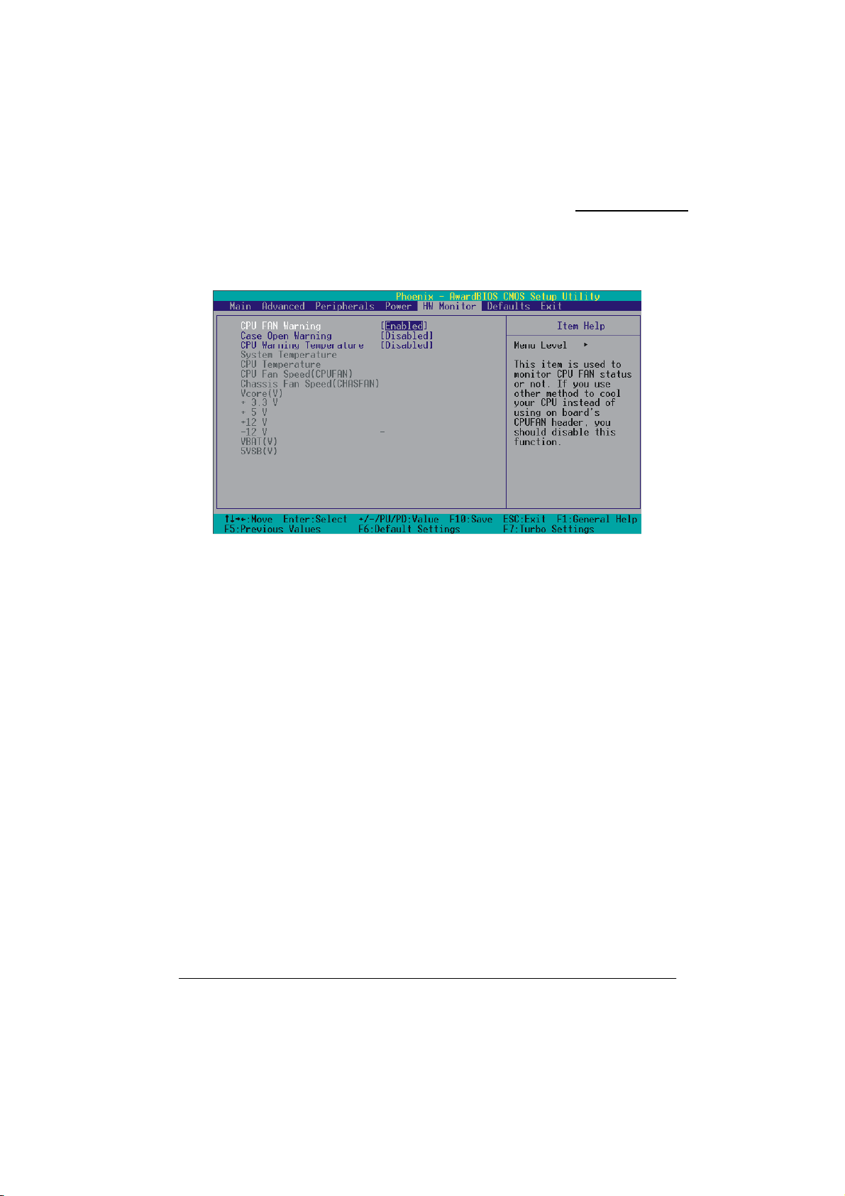
Hardware Monitor
KM400A Series
CPU FAN Warning
This item is used to monitor the “CPUFAN” header on the mainboard and warn the user (during
POST) if the CPU fan is not operational or not plugged in. If you are not using the “CPUFAN”
power header to supply power to your CPU fan, you must disable this feature.
Options: Disabled、Enabled (default)
Case Open Warning
If this function is set to “Enabled” and the case had been previously opened, the system will
automatically display alert messages on the screen when you power on your computer. If this
function is set to “Disabled”, the system will not show alert messages when you power on your
computer even if the case is opened by others.
Options: Disabled (default)、Enabled
CPU Warning Temperature
When the CPU temperature is higher than this setting, the warning mechanism will be activated.
Options: Disabled (default)、50℃/122℉、53℃/127℉、56℃/133℉、60℃/140℉、63℃/145
66℃/151℉、70℃/158℉。
℉、
43
Page 48
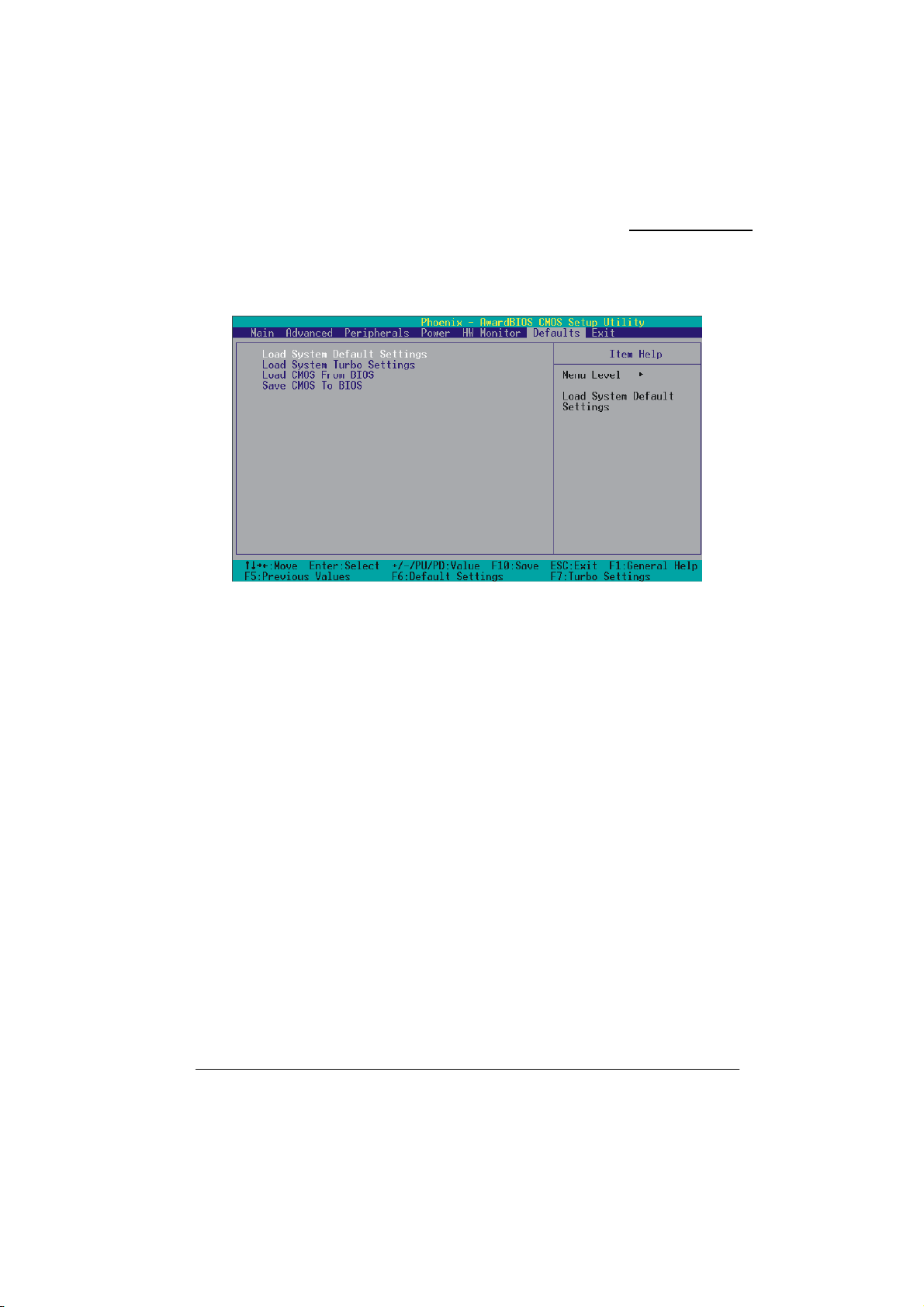
Load Defaults
KM400A Series
Load System Default Settings
Load System Default Settings.
Load System Turbo Settings
Load System Turbo Settings.
Load CMOS From BIOS
Load defaults from flash ROM for systems without batteries.
Save CMOS To BIOS
Save defaults to flash ROM for systems without batteries.
44
Page 49
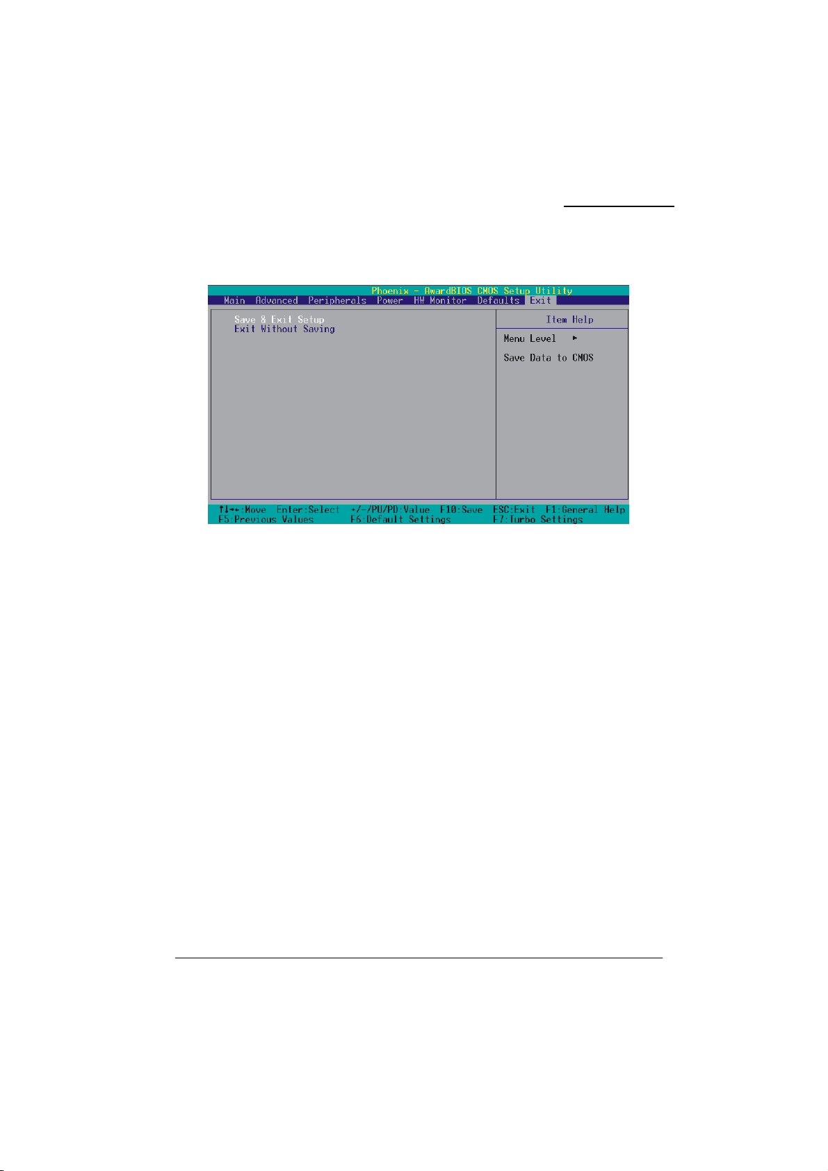
Exit Menu
KM400A Series
Save & Exit Setup
Save all configuration changes to CMOS (memory) and exit setup. A confirmation message will be
displayed before proceeding.
Exit Without Saving
Abandon all changes made during the current session and exit setup. A confirmation message will be
displayed before proceeding.
45
Page 50
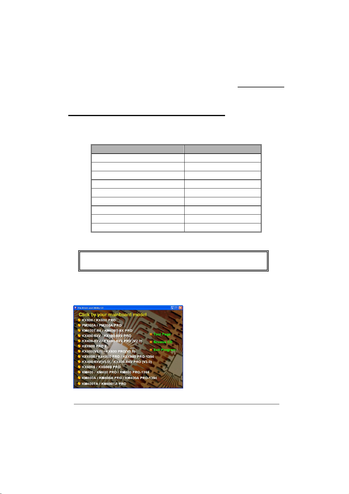
Chapter 3: Software Setup
Software List
Microsoft DirectX 9.0b Windows 9X /ME /2000 /XP
Adobe Acrobat Reader Windows 9X /ME /2000 /XP
Category Platform
VIA 4 IN 1 Driver Windows 9X /ME /2000 /XP
VIA LAN Driver Windows 9X /ME /2000 /XP
VIA Audio Driver Windows 9X /ME /2000 /XP
VIA VGA Driver Windows 9X /ME /2000 /XP
VIA Serial ATA Driver Windows 9X /ME /2000 /XP
VIA USB 2.0 Driver Windows 9X /ME
Trend PC-Cillin 2002 Windows 9X /ME /2000 /XP
KM400A Series
Software Installation
◎ The screen and images are only for general reference. The version of the screens
you received with your software may vary slightly.
Place the Driver CD into the CD-ROM drive and the Installation Utility will auto-run. You can also
launch the Driver CD Installation Utility manually by executing the VIA.exe program on the Driver
CD. These examples below are the driver CD with Windows
steps. (For more details, please refer to the Readme.txt files that in each folder of the Driver CD.)
46
®
XP operating system, please follow the
1. The first screen (Main Screen) will display
several buttons. Click “KM400A/ KM400A
PRO/ KM400A PRO-1394”.
Page 51
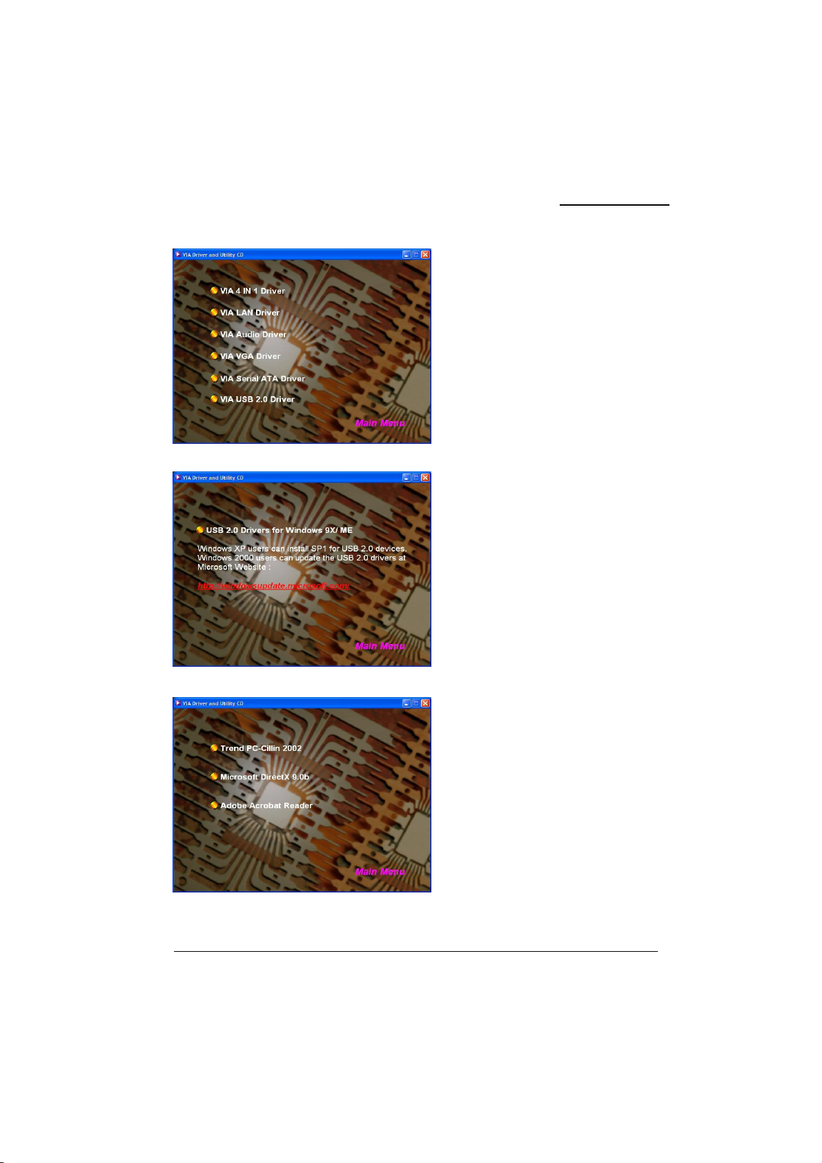
KM400A Series
2. On the next screen, click the drivers that
you want to install.
3. If you click the “VIA USB2.0 Driver” from
the screen in step 2, it will display the screen
as left.
4. Back to the main screen, click the “Tool
Page” button, you can choose the software to
install.
Note: You can click the “Finish Program”
button on any screen to exit the Driver CD
utility.
47
Page 52

KM400A Series
New installation of Windows® 2000/XP using a Serial ATA drive as the
boot device.
Follow the instructions in this section if you are performing a new installation of Windows® 2000/XP
and you wish to boot from a drive attached to the SATA connector.
1. Copy the “VIA Serial ATA Driver” from the bundle CD Driver to a floppy disk. 【CD File
Location Path => D: \ Driver \ SATA\ 2.20D\ ……】
2. Power off the system. Connect the SATA hard disk to one of the SATA connectors. Power up
the system.
3. Place your Windows 2000/XP CD into the CD-ROM/DVD drive. When the “Windows Setup”
screen displays, press “F6”.
4. Press 's' when setup asks if you want to specify an additional device. Insert the floppy disk
which includes the “VIA Serial ATA Driver” into the floppy drive.
Press 'Enter' and select the appropriate OS device driver.
5. Press 'Enter' again to continue the setup process.
6. Follow the setup instructions and select your choice for partition and file system.
7. After setup examines your disks, it will copy files to the Windows 2000/ XP installation folders
and restart the system. After the system is rebooted the setup program will continue with the
installation all the way to completion.
8. Wait until Windows 2000/ XP finishes installing devices, regional settings, networking settings,
components, and the final set of tasks. Reboot the system if you are asked to do so.
48
Page 53

KM400A Series
Chapter 4: Troubleshooting
Problem 1:
No power to the system. Power light does not illuminate. Fan inside power supply does not turn on.
Indicator lights on keyboard are not lit.
Causes:
1. Power cable is unplugged.
2. Defective power cable.
3. Power supply failure.
4. Faulty wall outlet; circuit breaker or fuse blown.
Solutions:
1. Make sure power cable is securely plugged in.
2. Replace cable.
3.Contact technical support.
4.Use different socket, repair outlet, reset circuit breaker or replace fuse.
Problem 2:
System inoperative. Keyboard lights are on, power indicator lights are lit, hard drive is active but
system seems “hung”
Causes: Memory DIMM is partially dislodged from the slot on the mainboard.
Solutions:
1. Power Down
2. Using even pressure on both ends of the DIMM, press down firmly until the module snaps into
place.
Problem 3:
System does not boot from the hard disk drive but can be booted from the CD-ROM drive.
Causes:
1. Connector between hard drive and system board unplugged.
2. Damaged hard disk or disk controller.
3. Hard disk directory or FAT is corrupted.
Solutions:
1. Check the cable running from the disk to the disk controller board. Make sure both ends are
securely attached. Check the drive type in the standard CMOS setup.
2. Contact technical support.
3. Backing up the hard drive is extremely important. Make sure your periodically perform backups to
avoid untimely disk crashes.
49
Page 54

KM400A Series
Problem 4:
System only boots from the CD-ROM. The hard disk can be read and applications can be used but
booting from the hard disk is impossible.
Causes: Hard Disk boot sector has been corrupted.
Solutions: Back up data and applications files. Reformat the hard drive. Re-install applications and
data using backup disks.
Problem 5:
Error message reading “SECTOR NOT FOUND” displays and the system does not allow certain data
to be accessed.
Causes: There are many reasons for this such as virus intrusion or disk failure.
Solutions: Back up any salvageable data. Then performs low level format, partition, and then a high
level format the hard drive. Re-install all saved data when completed.
Problem 6:
Screen message says “Invalid Configuration” or “CMOS Failure.”
Causes: Incorrect information entered into the BIOS setup program.
Solutions: Review system’s equipment. Reconfigure the system.
Problem 7:
The Screen is blank.
Causes: No power to monitor.
Solutions: Check the power connectors to the monitor and to the system.
Problem 8:
Blank screen.
Causes:
1. Memory problem.
2. Computer virus.
Solutions:
1. Reboot computer. Reinstall memory. Make sure that all memory modules are securely installed.
2. Use anti-virus programs to detect and clean viruses.
Problem 9:
Screen goes blank periodically.
Causes: Screen saver is enabled.
Solutions: Disable screen saver.
50
Page 55

KM400A Series
Problem 10:
Keyboard failure.
Causes: Keyboard is disconnected.
Solutions: Reconnect keyboard. Replace keyboard if you continue to experience problems.
Problem 11:
No color on screen.
Causes:
1. Faulty Monitor.
2. CMOS incorrectly set up.
Solutions:
1. If possible, connect monitor to another system. If no color appears, replace monitor.
2. Call technical support.
Problem 12:
The screen displays “C: drive failure.”
Causes: Hard drive cable not connected properly.
Solutions: Check hard drive cable.
Problem 13:
Cannot boot the system after installing a second hard drive.
Causes:
1. Master/slave jumpers not set correctly.
2. Hard drives are not compatible / different manufacturers.
Solutions:
1. Set master/slave jumpers correctly.
2.Run SETUP program and select the correct drive types. Call drive manufacturers for possible
compatibility problems with other drives.
Problem 14:
Missing operating system on hard drive.
Causes: CMOS setup has been changed.
Solutions: Run setup and select the correct drive type.
Problem 15:
Certain keys do not function.
Causes: Keys jammed or defective.
Solutions: Replace keyboard.
51
Page 56
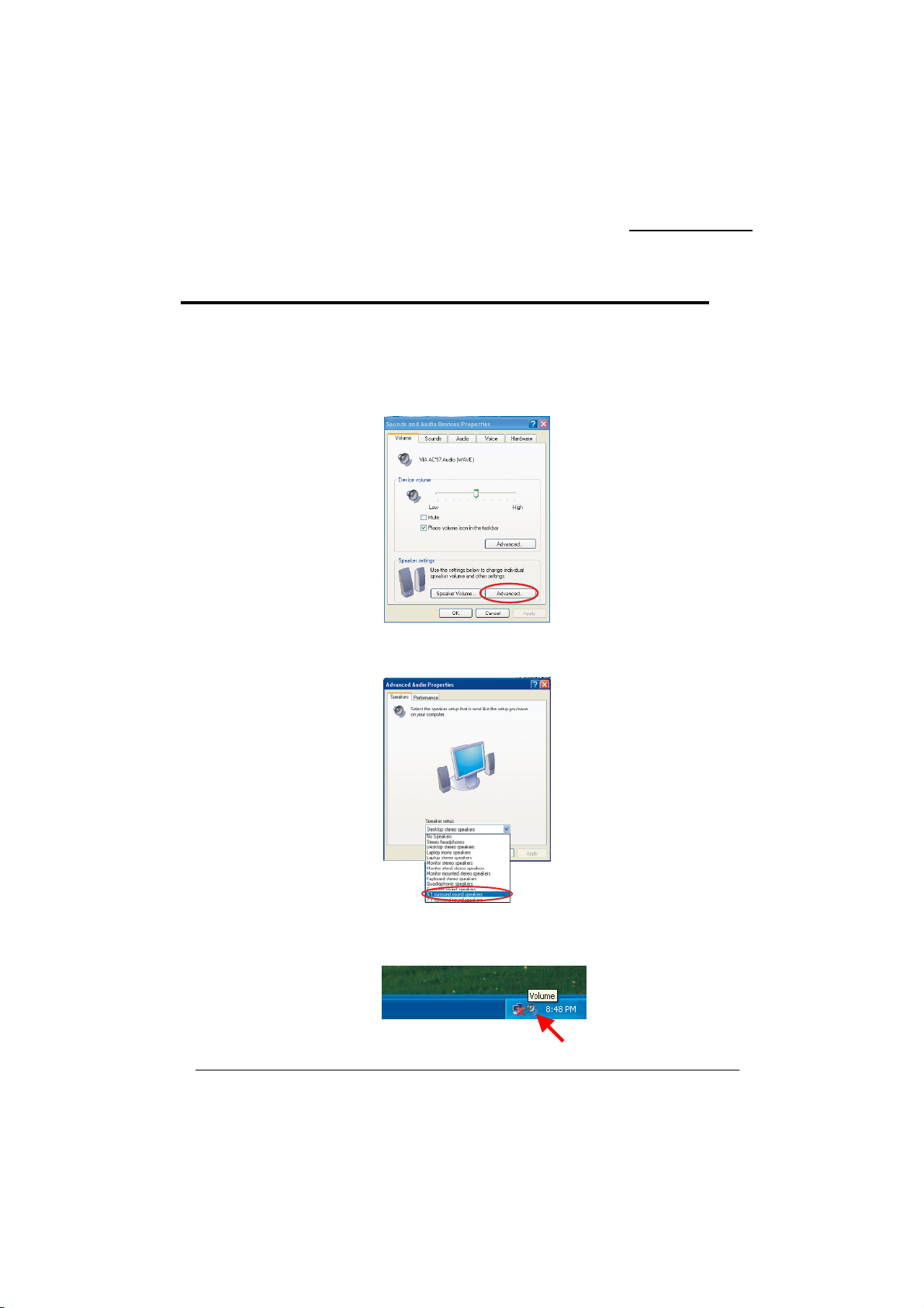
KM400A Series
Appendix I: Super 5.1 Channel Setup
This appendix describes the installation procedures for 5.1 Channel Setup. Note that if your
operating system is Windows 98/ ME/ 2000, go directly to step 3.
1. Beginning with the “Start” button, select
Audio Devices Sounds and Audio Devices. The screen below will display. First check the “Place
volume icon in the taskbar” in the Device volume block. Then press the “Advanced…” button to
configure the speaker settings.
2. At the “Advanced Audio Properties” screen use the drop-down box to select the “5.1 surround
sound speakers”. Click “Apply” to enable the 5.1 channel audio effect.
3. On your desktop, double click the volume icon that is on the desk bar.
(Note: As described earlier, begin with this step if your system has Windows 98/ ME/ 2000)
Setting
Control Panel
Sounds, Speech, and
52
Page 57
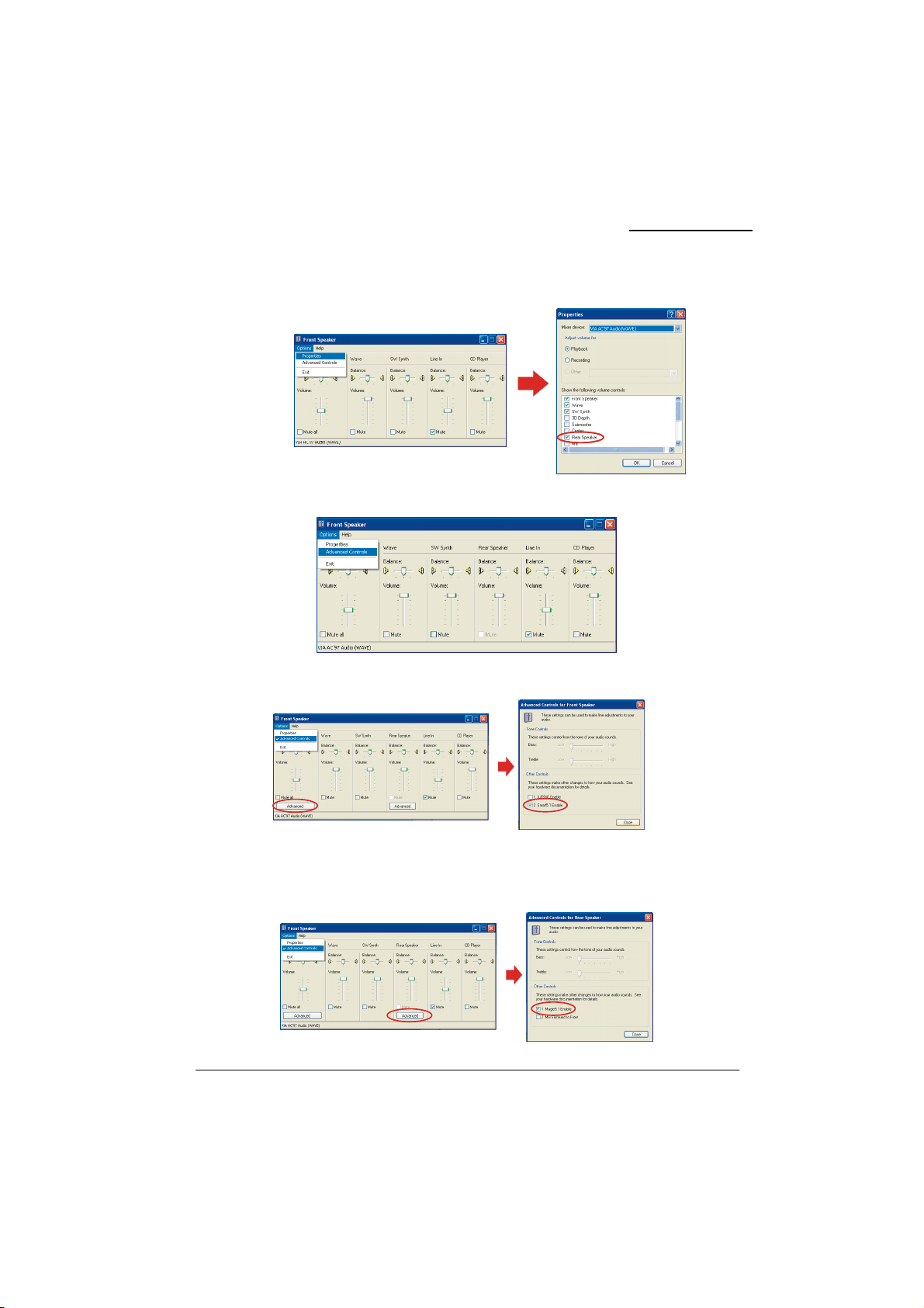
KM400A Series
4. On the “Front Speaker” screen, select “Options Properties”, then check “Rear Speaker” item
and click OK.
5. Also on the “Front Speaker” screen, select “Options Advanced Controls”.
6. Next, click the “Advanced” button of the Front Speaker, then check the “Smart5.1 Enable”.
7. Finally, click the “Advanced” button of the Rear Speaker, then check the “Magic5.1 Enable”. This
is the final step in configuring “Super 5.1 Channel Audio Effect”.
(If you broadcast a DVD with a DVD-ROM, please skip this step.)
53
Page 58
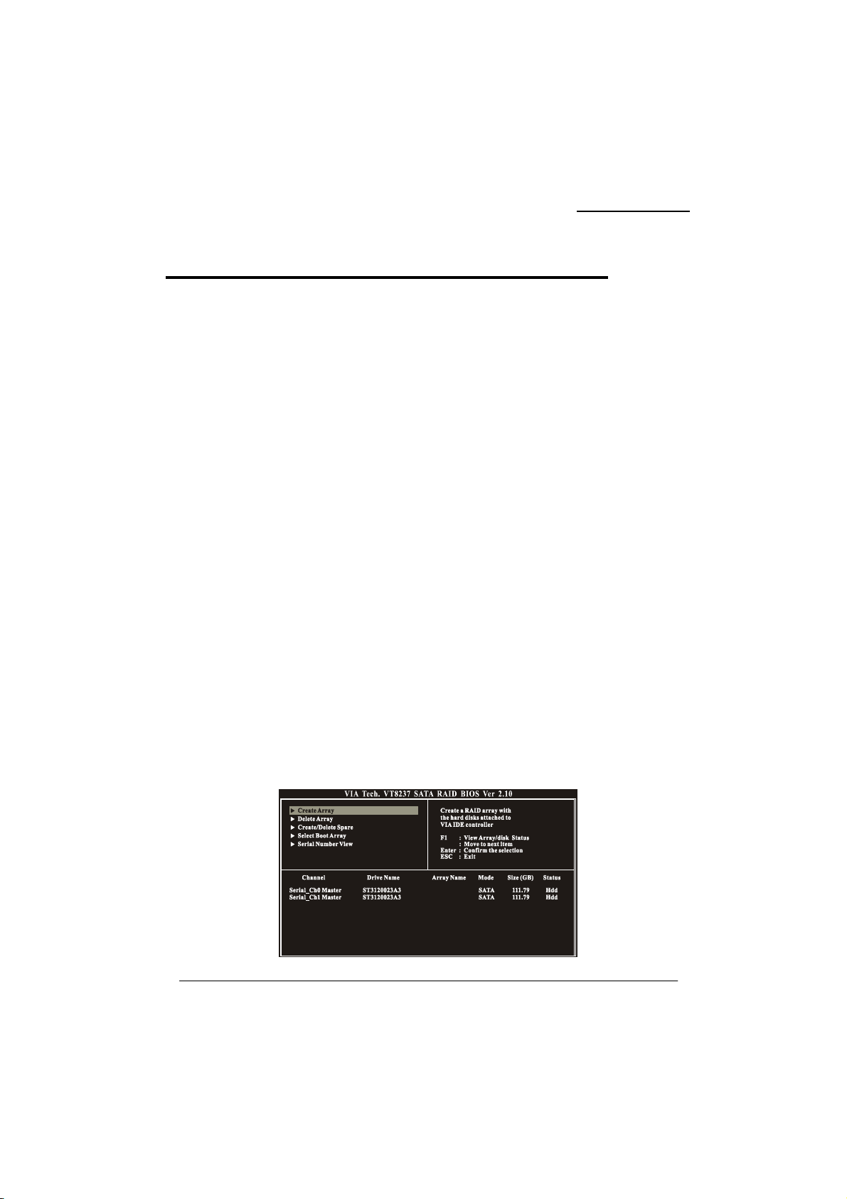
KM400A Series
Appendix II: SATA RAID 0/1 Setup
Introduction to RAID
(Redundant Array of Independent Disks)
RAID technology is a sophisticated disk management system that manages multiple disk drives,
enhancing I/O performance and providing redundancy in order to prevent the loss of data in case any
of the individual disks fail. The SATA RAID facility on this board provides RAID 0 (striped), RAID
1 (mirrored) and RAID SPAN.
Disk Striping (RAID 0)
Striping is a performance-oriented, non-redundant disk storage technology. With RAID striping,
multiple disks are used to form a larger virtual disk. Data is then striped or mapped across all the
physical disks. In this way modern SATA and ATA bus mastering technology can be used to perform
multiple I/O operations in parallel, enhancing performance. While Striping is discussed as a RAID
Set type, it actually does not provide fault tolerance.
Disk Mirroring (RAID 1)
With Disk Mirroring there is a redundant disk that mirrors the main disk. Data that is written to the
main disk is also written to the redundant disk. This redundancy provides fault tolerant protection
from a single disk failure. If a read/write failure occurs on one drive, the system can still read and
write data using the other drive.
RAID SPAN
RAID SPAN is not one of the standard RAID levels. It is however considered a JBOD (Just Bundle
Of Disks) configuration which simply uses multiple disks to form a larger virtual disk without any
other specialized disk management functionality.
RAID BIOS Configuration
When the system boots up during the POST (Power-On Self Test), the user will be given an
opportunity to enter the “VIA RAID BIOS Configuration” utility. Wait for the following prompt:
Press <Tab> Key into User Window
Then press the “Tab” key to enter the VIA RAID BIOS Configuration utility. The VIA RAID BIOS
screen will display as shown below.
54
Page 59
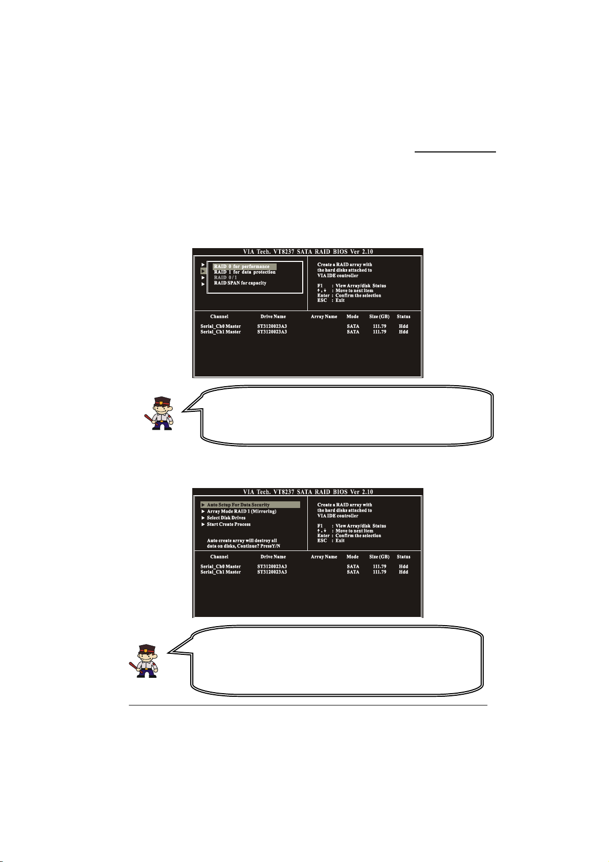
play
KM400A Series
Create Array
1. The “Create Array” option will allow you to initialize a RAID array. Choose the “Create
Array” on the main screen and press <Enter>. The screen below will display. According to
your needs, select “RAID 0 for performance” (striping), “RAID 1 for data protection”
(mirroring) or “RAID SPAN for capacity” (JBOD). Then press <Enter>.
2. Next, choose the “Auto Setup for Data Security” option and press <Enter>. The screen will
display a confirmation message as shown below. Press <Y> to continue with the creation of
the new array.
Attention
The “Channel”、“Drive Name”、“Mode”、“Size (GB)”, located at the
bottom portion of the screen above, reflect the devices that are currently
installed on the SATA connectors. The example information above may
therefore differ with the information that dis
s on your screen.
Attention
For RAID 1 (Mirrored Arrays), you can manually select the “source
device” instead of having the system determine it for you. After step 1,
select the “Select Disk Drives” to manually select the “source device”.
Then choose the “Start Create Process” and press <Enter> to complete
the RAID 1 array creation.
55
Page 60
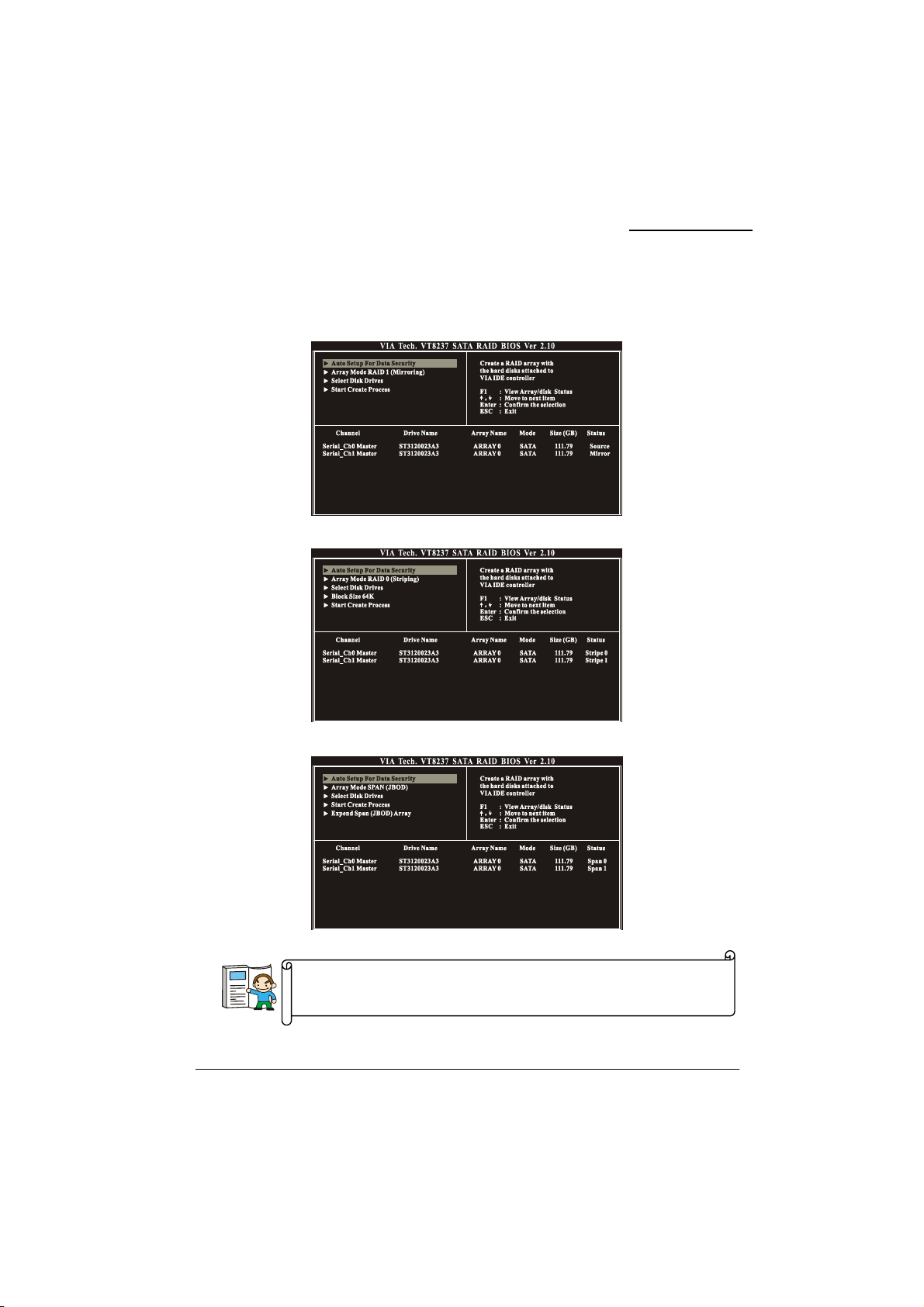
KM400A Series
3. After the array has been successfully created, one of the screens will display as shown below
according to the type of array you created.
RAID 1 mode
RAID 0 mode
RAID SPAN mode
The RAID 0 screen (above) contains the option, “Block Size 64K”. With
this option you can manually select the block size for your array. However,
we recommend that you to select the “64K” for optimal performance.
56
Page 61
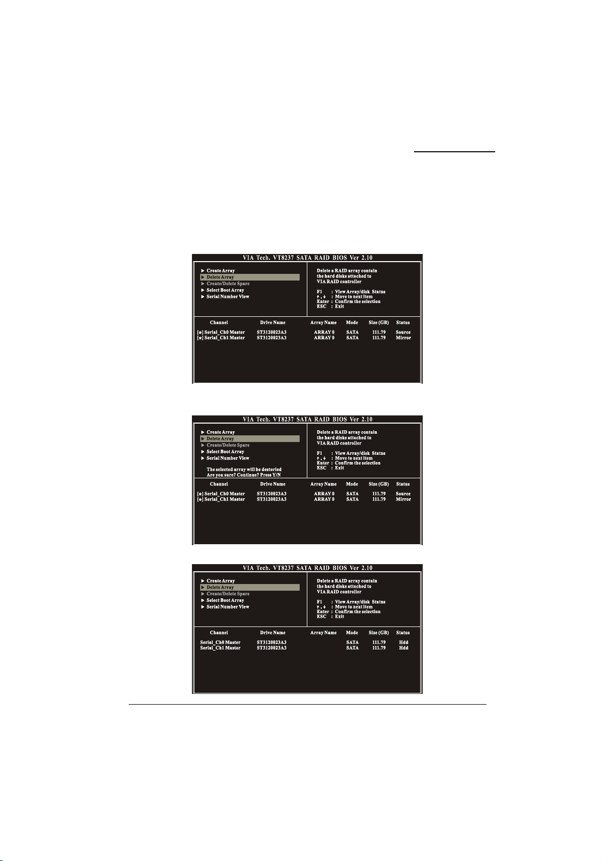
KM400A Series
Delete Array
1. You can delete an existing array with the “Delete Array” option on the main screen. Choose
the “Delete Array” option and press <Enter>. Then press the <Enter> key once again and the
system will mark all the existing SATA devices with an asterisk (as shown below in the
bottom section). (Note that the example information below may differ slightly depending on
the RAID type you are configuring.)
2. Press <Enter>. A warning/confirmation message will display (as shown below). Press <Y> to
confirm.
3. After the array is successfully deleted, the screen will display as shown below.
57
Page 62
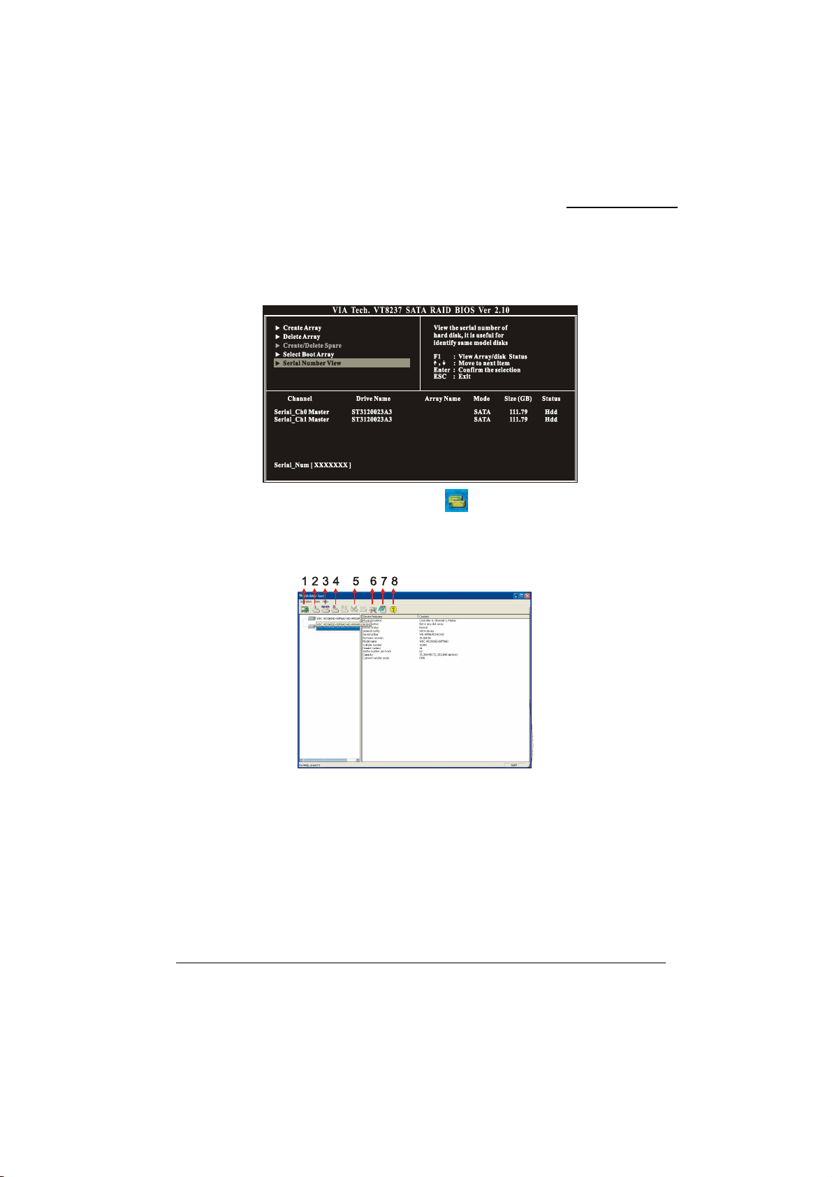
KM400A Series
Serial Number View
You can choose the “Serial Number View” to view the serial number of the serial ATA device. The
serial number is assigned to the device by the manufacturer.
VIA RAID Tool (VIA Raid Tool icon )
The VIA RAID Tool allows the user to configure and monitor RAID arrays from the Windows
environment. After booting your operating system, click the “VIA RAID Tool” icon from the
Windows desktop. The Screen below will display. You can simply click on one of the toolbar buttons
on the menu bar to execute their respective functions.
Toolbar Button 1: View the controller status.
Toolbar Button 2: Create a array with RAID 1.
Toolbar Button 3: Create a array with SPAN.
Toolbar Button 4: Create a array with RAID 0.
Toolbar Button 5: Delete the array that you created before.
Toolbar Button 6: View the devices status.
Toolbar Button 7: View the event log.
Toolbar Button 8: Help topics.
58
 Loading...